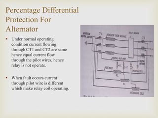
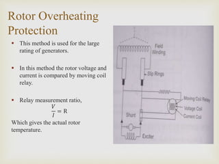
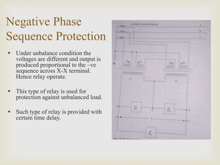
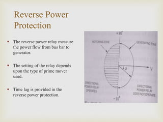
Sharad Institute of Technology College of
Engineering, Yadrav (Ichalkarnji)
A
Presentation On
generator protection
Presented By,
Mr. Chetan Patil.
Assistant Professor
Department of Electrical Engineering

 Percentage Differential Protection For Alternator.
 Restricted Earth Fault Relay.
 Rotor Overheating Protection.
 Negative Phase Sequence Protection.
 Reverse Power Protection.
 Generator Transformer Unit Protection.
 3 Zone Protection.
 Microprocessor Based Relay.
 Numerical Relay.
 Causes of Overvoltage.
Contents
Percentage Differential
Protection For
Alternator
 Under normal operating
condition current flowing
through CT1 and CT2 are same
hence equal current flow
through the pilot wires, hence
relay is not operate.
 When fault occurs current
through pilot wire is different
which make relay coil operating.
Restricted Earth
Fault Relay
 In practice the restricted earth
fault protection is used to
protect about 85% of
generator winding against
phase to earth fault.
 If we want to obtain 100%
protection to the generator
winding a separate earth fault
protection system is used.
Rotor Overheating
Protection
 This method is used for the large
rating of generators.
 In this method the rotor voltage and
current is compared by moving coil
relay.
 Relay measurement ratio,
𝑉
𝐼
= R
Which gives the actual rotor
temperature.
Negative Phase
Sequence Protection
 Under unbalance condition the
voltages are different and output is
produced proportional to the –ve
sequence across X-X terminal.
Hence relay operate.
 This type of relay is used for
protection against unbalanced load.
 Such type of relay is provided with
certain time delay.
Reverse Power
Protection
 The reverse power relay measure
the power flow from bus bar to
generator.
 The setting of the relay depends
upon the type of prime mover
used.
 Time lag is provided in the
reverse power protection.
Generator
Transformer Unit
Protection
 An overall biased differential
protection is provided to protect
both the generator and
transformer as a one unit,
generator transformer protection
is used.
 In this type of protection
harmonic restraining relay is not
used.
3 Zone Protection
 First zone: The first zone
setting is 85 to 90% of line
length with highest speed of
protection.
 Second zone: The second
zone relay at ‘A’ provide
remaining 15 to 10%
protection.
 Third zone: The third zone
relay at ‘A’ provides backup
protection for section AB,
BC, CD.
Microprocessor
Based Relay
 This type of protection scheme
is more accurate, compact,
reliable and fast.
 The microprocessor compares
the digital output of A/D
converter with a fixed reference
value and send signal for
tripping.
Numerical Relay
 It employs a number of
distance relays which measure
the impedance or some
component of the line
impedance at the relay
location.
 The input voltage and current
signals in the form of discrete
number system.

Causes Of Overvoltage
•Switching surge
•Insulation failure
Internal
Cause
•Lightning
External
Cause

 There are many faults in alternator such as earth fault, overheating,
negative phase sequence, reverse power etc.
 The protective equipment's such as CB, relays are located in such way
that generator is completely disconnected from rest of system till fault
is cleared and save the cost of equipment for reinstalling.
Conclusion

Thank You

 Power system protection & Switchgear: B.Ram &
B.N. Vishwakarma.
 Switchgear & Protection: Sunil S.Rao, Khanna
Publications.
References

Generator protection

  • 1.
    Sharad Institute ofTechnology College of Engineering, Yadrav (Ichalkarnji) A Presentation On generator protection Presented By, Mr. Chetan Patil. Assistant Professor Department of Electrical Engineering
  • 2.
      Percentage DifferentialProtection For Alternator.  Restricted Earth Fault Relay.  Rotor Overheating Protection.  Negative Phase Sequence Protection.  Reverse Power Protection.  Generator Transformer Unit Protection.  3 Zone Protection.  Microprocessor Based Relay.  Numerical Relay.  Causes of Overvoltage. Contents
  • 3.
    Percentage Differential Protection For Alternator Under normal operating condition current flowing through CT1 and CT2 are same hence equal current flow through the pilot wires, hence relay is not operate.  When fault occurs current through pilot wire is different which make relay coil operating.
  • 4.
    Restricted Earth Fault Relay In practice the restricted earth fault protection is used to protect about 85% of generator winding against phase to earth fault.  If we want to obtain 100% protection to the generator winding a separate earth fault protection system is used.
  • 5.
    Rotor Overheating Protection  Thismethod is used for the large rating of generators.  In this method the rotor voltage and current is compared by moving coil relay.  Relay measurement ratio, 𝑉 𝐼 = R Which gives the actual rotor temperature.
  • 6.
    Negative Phase Sequence Protection Under unbalance condition the voltages are different and output is produced proportional to the –ve sequence across X-X terminal. Hence relay operate.  This type of relay is used for protection against unbalanced load.  Such type of relay is provided with certain time delay.
  • 7.
    Reverse Power Protection  Thereverse power relay measure the power flow from bus bar to generator.  The setting of the relay depends upon the type of prime mover used.  Time lag is provided in the reverse power protection.
  • 8.
    Generator Transformer Unit Protection  Anoverall biased differential protection is provided to protect both the generator and transformer as a one unit, generator transformer protection is used.  In this type of protection harmonic restraining relay is not used.
  • 9.
    3 Zone Protection First zone: The first zone setting is 85 to 90% of line length with highest speed of protection.  Second zone: The second zone relay at ‘A’ provide remaining 15 to 10% protection.  Third zone: The third zone relay at ‘A’ provides backup protection for section AB, BC, CD.
  • 10.
    Microprocessor Based Relay  Thistype of protection scheme is more accurate, compact, reliable and fast.  The microprocessor compares the digital output of A/D converter with a fixed reference value and send signal for tripping.
  • 11.
    Numerical Relay  Itemploys a number of distance relays which measure the impedance or some component of the line impedance at the relay location.  The input voltage and current signals in the form of discrete number system.
  • 12.
     Causes Of Overvoltage •Switchingsurge •Insulation failure Internal Cause •Lightning External Cause
  • 13.
      There aremany faults in alternator such as earth fault, overheating, negative phase sequence, reverse power etc.  The protective equipment's such as CB, relays are located in such way that generator is completely disconnected from rest of system till fault is cleared and save the cost of equipment for reinstalling. Conclusion
  • 14.
  • 15.
      Power systemprotection & Switchgear: B.Ram & B.N. Vishwakarma.  Switchgear & Protection: Sunil S.Rao, Khanna Publications. References