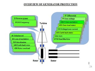
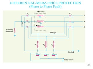
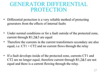
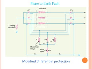
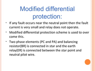
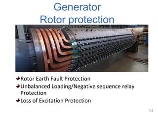
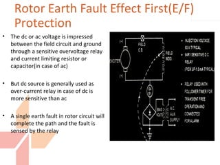
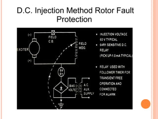
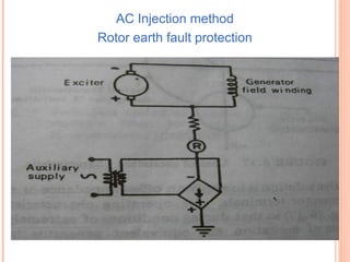
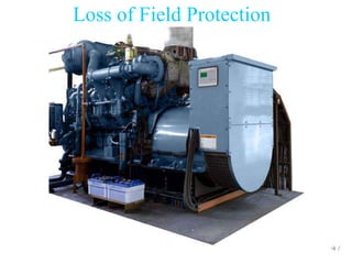
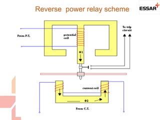
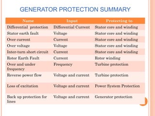
1
UNIT II VI-SEM 2016
ST. JOSEPH UNIVERSITY(TZ)
Protection Apparatus Schemes
Electrical Protection Schemes take actions only
after sensing the occurrence of the fault to
prevent the electrical systems from damage
Then why protections are required?
– to limit the damage to the components which
are under fault.
– to save the rest of the Power System.
2
• Generators
• Motors
• Transformer
• Buses
• Lines (transmission and distribution)
• Utilization equipment (domestic loads)
Note: Protective system cost is 4-5% of the total
cost in industries per IEEE
Basic Components to be Protected
3
Protection Zones
Unit Generator-Tx zone
Bus zone
Line zone
Bus zone
Transformer zone
Transformer zone
Bus zone
Generator
~
Reactor Bus Line Bus Reactor Bus Motor
Motor zone
4
• In electrical system, the generator, transformer and
motors are the most expensive equipments and
hence it is desirable to employ a protective system
• The basic electrical quantities those are likely to
change during abnormal fault conditions are current,
voltage, phase angle and frequency
• Protective components utilizes one or more of these
quantities to detect abnormal conditions in a power
system
Quantities Affected in Electrical
System
MAIN EQUIPMENT FOR
SWITCHGEAR OPERATION
 Potential transformer
 Current transformer
 Relay
 Circuit breaker
 DC Power Source for operation of the Circuit Breaker
and Relays
Switchgear is a general term covering a wide range
of equipments concerned with switching and
protection.
i.e. Circuit breaker, Isolator, Earth switch etc
6
GEConsumer&Industrial
Multilin
VVPP
VVSS
Relay
• Voltage (potential) transformers are used to isolate and step down
and accurately reproduce the scaled voltage for the protective
device or relay
• VT ratios are typically expressed as primary to secondary;
14400:120,
Voltage Transformers
VT
7
GEConsumer&Industrial
Multilin
• Current transformers are used to step primary system currents to
values usable by relays, meters, SCADA, transducers, etc.
• CT ratios are expressed as primary to secondary; 2000:5,
Current Transformers
 Fast operation Auto electric protective device
 Act at Abnormal condition.
 Energizing an Alarm
 Disconnect fault zone
 Use system supply to operate.
1. Electromagnetic/conventional Relays
2. Static/solid state Relays
Simple electromechanical relay
11
• Reliability
• Selectivity
• Speed
• Simple switchgear
Desirable Protection Attributes
12
Basic Functioning of Protection
Relay
13
• Getting Inputs from CT and/or PT, Relay
determines whether there is any fault
• If it detects any fault then gives trip command
to the circuit breaker
• Getting command, circuit breaker disconnects
the faulty sections from rest of the power
system.
Functioning of Protection Relay
14
Our current discussion will be
based on: Generator Protection
SEMINAR
•Transformer Protection(2.5marks for
Assignment1)
•Bus bar Protections Plus CT & PT
App(2.5marks for Assignment1)
TYPES OF GENERATOR
AC Generator DC Generator
Induction Generator
SYNCHRONOUS GENERATOR
Self Excited DC Generator
Separately Excited
AC GENERATOR
Synchronous Generator
Synchronous Generator : in this type the rotor speed is just equal to the flux
produce by the stator . And receiving field excitation from separate field supply
Asynchronous(Induction) Generator
Asynchronous or Induction : in this type Rotor speed is not equal the Flux
produced by the stator
Induction generator takes reactive power from the power system for field
excitation. If an induction generator is meant to supply a standalone load, a
capacitor bank needs to be connected to supply reactive power.
Due to lack of a separated field excitation , these machines are rarely used as
generator
AC GENERATOR
 Synchronous Generator
Asynchronous Generator
Field excitation
GENERATOR MAIN PARTS
 Parts: By Mechanical
Stator (Field winding)
Rotor (Armature winding)
 Parts: By Electrical
Armature winding
The winding which carries only the load current.
Field winding
The winding which carries only the field current required to
produce the magnetic flux.
19
SCHEME OF GENERATOR
PROTECTION
• CLASS A TRIPPING
 This is adopted for those electrical faults of Generator and
Generator transformer(TG) and unit auxiliary transformer(UAT)
for which tripping can not be delayed.
- Generator HV side CB
- Field Circuit Breaker
- LV side incomer breakers of UAT
- Auto changeover from unit to station for unit auxiliaries and
tripping of turbine
• CLASS B TRIPPING
This is adopted for all turbine faults (Mechanical) and for some
Electrical faults of Generator, Generator transformer and unit
Auxiliary transformer for which it is safe to trip the turbine after
sometime
20
SCHEME OF GENERATOR
PROTECTION
• CLASS C TRIPPING
This is adopted for all faults beyond the Generator system
which can be cleared by tripping of Generator transformer HV
side CB alone
 In this case the TG set runs with High Power-Low Power
bypass system in operation and the Generator continues to
feed the unit auxiliary load through unit auxiliary transformers.
FAULT OCURRENCE & FAULT
CLASSIFICATION
Insulation failure
• Tends to increase with rising
temp
• Insulation failure may cause LLL
or LLG.
• Bring winding in to direct contact
with core plates.
• Any failure to restrict earth fault
may result into core plate
damage.
• Insulation of rotor winding is also
important
Stator Fault
Rotor fault
Abnormal Running Condition
INSULATION FAILURE
FAULT
 Insulation failure.
 Tends to deteriate with rising temp.
 Insulation failure may cause inter-turn fault, ph to
ph or earth fault.
 Bring winding in to direct contact with core plates.
 Any failure to restrict earth fault may result into core
plate damage.
 Insulation of rotor winding is also important.
PROTECTION APPLIED
TO GENERATOR
 Relays to detect faults outside generator
 Relays to detect faults in side generator
 Over speed protections.
 Temp measuring device for bearings, stator
winding, Oil temp.
24
Generator
Stator protection:
Stator faults include the following-
i. Phase-to-earth faults
ii. Phase-to-phase faults
iii.Inter-turn faults
From these phase faults and inter turn faults are less
common ,these usually develop into an earth faults.
This causes-
• Arcing to core
• Damage of conductor and insulation
26
DIFFERENTIAL/MERZ-PRICE PROTECTION
(Phase to Phase Fault)
27
• Differential protection is a very reliable method of protecting
generators from the effects of internal faults
• Under normal conditions or for a fault outside of the protected zone,
current through R1,2&3 are equal
• Therefore the currents in the current transformers secondary are also
equal, i.e. CT1 = CT2 and no current flows through the relay
• If a fault develops inside of the protected zone, currents CT1 and
CT2 are no longer equal, therefore current through R1,2&3 are not
equal and there is a current flowing through the relay.
GENERATOR DIFFERENTIAL
PROTECTION
Modified differential protection
Phase to Earth Fault
Modified differential
protection:
• If any fault occurs near the neutral point then the fault
current is very small and relay does not operate.
• Modified differential protection scheme is used to over
come this.
• Two phase elements (PC and PA) and balancing
resistor(BR) is connected in star and the earth
relay(ER) is connected between the star point and
neutral pilot wire.
Stator Earth Fault Relay
mmmmmm
mmmmmm
mmmmmm
mmmmmm
mmmmmm
Loading
resistor
Over voltage relay
With time delay
STATOR EARTHFAULT RELAY
INTER-TURN FAULT
PROTECTION
87’s are relays
INTER-TURN FAULT RELAY
OPERATION
 The inter-turn fault is a short circuit between the turns of the
same phase winding
 The current transformers are connected in the two parallel paths
of the each phase winding
 The secondaries of the current transformers are cross
connected. The current transformers work on circulating current
principle
 The relay is connected across the cross connected secondaries of
the current transformers.
34
Generator
Rotor protection
Rotor Earth Fault Protection
Unbalanced Loading/Negative sequence relay
Protection
Loss of Excitation Protection
• The dc or ac voltage is impressed
between the field circuit and ground
through a sensitive overvoltage relay
and current limiting resistor or
capacitor(in case of ac)
• But dc source is generally used as
over-current relay in case of dc is
more sensitive than ac
• A single earth fault in rotor circuit will
complete the path and the fault is
sensed by the relay
Rotor Earth Fault Effect First(E/F)
Protection
D.C. Injection Method Rotor Fault
Protection
AC Injection method
Rotor earth fault protection
38
• Unbalance loading causing negative sequence currents which
produce a reverse sequence rotating field in the machine
• This induces double frequency eddy currents in the rotor
leading to overheating and
• Unbalance loading gives rise to double frequency eddy
currents induced in rotor which may cause excessive
overheating
NEGATIVE PHASE
SEQUENCE CURRENT
PROTECTION
Negative phase sequence
protection:
Negative Sequence Vectors
1250
1160
1200
Negative phase sequence
protection:
• Unbalance may cause due to single phase
fault or unbalanced loading and it gives rise to
negative sequence current .
• This current in rotor causes rotor overheating
and damage to the rotor.
• This can be protected by negative sequence
current filter with over current relay.
Negative phase sequence protection:
Field(Excitation) failure protection
• This normally closed contact of sensitive magnetic coil relay
remains open as the relay coil is energized by shunted
excitation current during normal operation of the excitation
system.
• As soon as there is any failure of excitation system, the relay
coil becomes de-energized and the normally closed contact
closes the supply across the coil of timing relay T1.
• As the relay coil is energized, the normally open contact of
this relay T 1 is closed.
• This contact closes the supply across another timing relay T 2
with an adjustable pickup time delay of 2 to 10 seconds which
in turn operates tripping coil
FIELD(EXCITATION) CAUSES
 Loss of generator field excitation under normal running conditions may
arise due to any of the following condition.
1. Failure of brush gear.
2. unintentional opening of the field circuit breaker.
3. Failure of AVR control
4. Field open circuit
5. Field short circuit
6. Accidental tripping of field Breaker
7. Loss of supply to main Exciter
8. Poor Brush contact in Exciter
9. Field Current Breaker Latch Failure
10. Slip ring Flash Over
Loss of excitation Effect
When the excitation of generator is lost it operate as a
Induction generator. It derives excitation from the
system and supply power at leading power factor.
Which may cause-
 A fall in voltage & so loss of synchronism & system
instability.
 Over heating of rotor due to induction current on it.
A protection having MHO characteristic
is used to detect loss of field.
46
• Senses when the generator’s excitation system
has been lost.
• When generator loses excitation it will steal
excitation from other gensets & quickly
overheat the rotor due to induced slip-
frequency currents
• Reverse VAR protection overcome this
problem
Loss of Field Protection
47
Loss of Field Protection
 When prime-mover fails machine starts motoring
and draws electrical power from the system and
this is known as inverted operation .
 The generator can be protected from inverted
operation by using single-element directional
power relay(reverse power relay) which senses
the direction of power flow.
 Failure of the prime mover of a generator set ,will
keep the set running as asynchronous
compensator
Reverse Power Protection
Reverse power relay scheme
Over voltage protection:
Over voltage may be caused due to-
 Transient over voltage in the transmission line
due to lightening.
 Defective operation of the voltage regulator.
 Sudden loss of load due to line tripping.
The protection is provided with an over voltage
relay.
Overcurrent protection:
• Overloading of the machine causes overheating in the
stator winding.
• This can be prevented by using over-current relay with
time delay adjustment.
• But overheating not only depends on over-current but
also the failure of the cooling system in the generator.
• So temperature detector coils such as thermistors or
thermocouples are used at various points in stator
winding for indication of the temperature.
52
• Resistance temperature detectors are used to
sense winding temperatures.
Temperature Protection
EQUIPMENT GROUNDING
 Prevents shock exposure of personnel
 Provides current carrying capability for the ground-fault
current
 Grounding includes design and construction of substation
ground mat and CT and VT safety grounding
GENERATOR PROTECTION SUMMARY
Name Input Protecting to
Differential protection Differential Current Stator core and winding
Stator earth fault Voltage Stator core and winding
Over current Current Stator core and winding
Over voltage Voltage Stator core and winding
Inter-turn short circuit Current Stator core and winding
Rotor Earth Fault Current Rotor winding
Over and under
frequency
Frequency Turbine protection
Reverse power flow Voltage and current Turbine protection
Loss of excitation Voltage and current Power System Protection
Back up protection for
lines
Voltage and current Generator protection
Questions?

Generator protection by a. kato

  • 1.
    1 UNIT II VI-SEM2016 ST. JOSEPH UNIVERSITY(TZ) Protection Apparatus Schemes Electrical Protection Schemes take actions only after sensing the occurrence of the fault to prevent the electrical systems from damage Then why protections are required? – to limit the damage to the components which are under fault. – to save the rest of the Power System.
  • 2.
    2 • Generators • Motors •Transformer • Buses • Lines (transmission and distribution) • Utilization equipment (domestic loads) Note: Protective system cost is 4-5% of the total cost in industries per IEEE Basic Components to be Protected
  • 3.
    3 Protection Zones Unit Generator-Txzone Bus zone Line zone Bus zone Transformer zone Transformer zone Bus zone Generator ~ Reactor Bus Line Bus Reactor Bus Motor Motor zone
  • 4.
    4 • In electricalsystem, the generator, transformer and motors are the most expensive equipments and hence it is desirable to employ a protective system • The basic electrical quantities those are likely to change during abnormal fault conditions are current, voltage, phase angle and frequency • Protective components utilizes one or more of these quantities to detect abnormal conditions in a power system Quantities Affected in Electrical System
  • 5.
    MAIN EQUIPMENT FOR SWITCHGEAROPERATION  Potential transformer  Current transformer  Relay  Circuit breaker  DC Power Source for operation of the Circuit Breaker and Relays Switchgear is a general term covering a wide range of equipments concerned with switching and protection. i.e. Circuit breaker, Isolator, Earth switch etc
  • 6.
    6 GEConsumer&Industrial Multilin VVPP VVSS Relay • Voltage (potential)transformers are used to isolate and step down and accurately reproduce the scaled voltage for the protective device or relay • VT ratios are typically expressed as primary to secondary; 14400:120, Voltage Transformers VT
  • 7.
    7 GEConsumer&Industrial Multilin • Current transformersare used to step primary system currents to values usable by relays, meters, SCADA, transducers, etc. • CT ratios are expressed as primary to secondary; 2000:5, Current Transformers
  • 8.
     Fast operationAuto electric protective device  Act at Abnormal condition.  Energizing an Alarm  Disconnect fault zone  Use system supply to operate.
  • 9.
  • 10.
  • 11.
    11 • Reliability • Selectivity •Speed • Simple switchgear Desirable Protection Attributes
  • 12.
    12 Basic Functioning ofProtection Relay
  • 13.
    13 • Getting Inputsfrom CT and/or PT, Relay determines whether there is any fault • If it detects any fault then gives trip command to the circuit breaker • Getting command, circuit breaker disconnects the faulty sections from rest of the power system. Functioning of Protection Relay
  • 14.
    14 Our current discussionwill be based on: Generator Protection SEMINAR •Transformer Protection(2.5marks for Assignment1) •Bus bar Protections Plus CT & PT App(2.5marks for Assignment1)
  • 15.
    TYPES OF GENERATOR ACGenerator DC Generator Induction Generator SYNCHRONOUS GENERATOR Self Excited DC Generator Separately Excited
  • 16.
    AC GENERATOR Synchronous Generator SynchronousGenerator : in this type the rotor speed is just equal to the flux produce by the stator . And receiving field excitation from separate field supply Asynchronous(Induction) Generator Asynchronous or Induction : in this type Rotor speed is not equal the Flux produced by the stator Induction generator takes reactive power from the power system for field excitation. If an induction generator is meant to supply a standalone load, a capacitor bank needs to be connected to supply reactive power. Due to lack of a separated field excitation , these machines are rarely used as generator
  • 17.
    AC GENERATOR  SynchronousGenerator Asynchronous Generator Field excitation
  • 18.
    GENERATOR MAIN PARTS Parts: By Mechanical Stator (Field winding) Rotor (Armature winding)  Parts: By Electrical Armature winding The winding which carries only the load current. Field winding The winding which carries only the field current required to produce the magnetic flux.
  • 19.
    19 SCHEME OF GENERATOR PROTECTION •CLASS A TRIPPING  This is adopted for those electrical faults of Generator and Generator transformer(TG) and unit auxiliary transformer(UAT) for which tripping can not be delayed. - Generator HV side CB - Field Circuit Breaker - LV side incomer breakers of UAT - Auto changeover from unit to station for unit auxiliaries and tripping of turbine • CLASS B TRIPPING This is adopted for all turbine faults (Mechanical) and for some Electrical faults of Generator, Generator transformer and unit Auxiliary transformer for which it is safe to trip the turbine after sometime
  • 20.
    20 SCHEME OF GENERATOR PROTECTION •CLASS C TRIPPING This is adopted for all faults beyond the Generator system which can be cleared by tripping of Generator transformer HV side CB alone  In this case the TG set runs with High Power-Low Power bypass system in operation and the Generator continues to feed the unit auxiliary load through unit auxiliary transformers.
  • 21.
    FAULT OCURRENCE &FAULT CLASSIFICATION Insulation failure • Tends to increase with rising temp • Insulation failure may cause LLL or LLG. • Bring winding in to direct contact with core plates. • Any failure to restrict earth fault may result into core plate damage. • Insulation of rotor winding is also important Stator Fault Rotor fault Abnormal Running Condition
  • 22.
    INSULATION FAILURE FAULT  Insulationfailure.  Tends to deteriate with rising temp.  Insulation failure may cause inter-turn fault, ph to ph or earth fault.  Bring winding in to direct contact with core plates.  Any failure to restrict earth fault may result into core plate damage.  Insulation of rotor winding is also important.
  • 23.
    PROTECTION APPLIED TO GENERATOR Relays to detect faults outside generator  Relays to detect faults in side generator  Over speed protections.  Temp measuring device for bearings, stator winding, Oil temp.
  • 24.
  • 25.
    Generator Stator protection: Stator faultsinclude the following- i. Phase-to-earth faults ii. Phase-to-phase faults iii.Inter-turn faults From these phase faults and inter turn faults are less common ,these usually develop into an earth faults. This causes- • Arcing to core • Damage of conductor and insulation
  • 26.
  • 27.
    27 • Differential protectionis a very reliable method of protecting generators from the effects of internal faults • Under normal conditions or for a fault outside of the protected zone, current through R1,2&3 are equal • Therefore the currents in the current transformers secondary are also equal, i.e. CT1 = CT2 and no current flows through the relay • If a fault develops inside of the protected zone, currents CT1 and CT2 are no longer equal, therefore current through R1,2&3 are not equal and there is a current flowing through the relay. GENERATOR DIFFERENTIAL PROTECTION
  • 28.
  • 29.
    Modified differential protection: • Ifany fault occurs near the neutral point then the fault current is very small and relay does not operate. • Modified differential protection scheme is used to over come this. • Two phase elements (PC and PA) and balancing resistor(BR) is connected in star and the earth relay(ER) is connected between the star point and neutral pilot wire.
  • 30.
  • 31.
  • 32.
  • 33.
    INTER-TURN FAULT RELAY OPERATION The inter-turn fault is a short circuit between the turns of the same phase winding  The current transformers are connected in the two parallel paths of the each phase winding  The secondaries of the current transformers are cross connected. The current transformers work on circulating current principle  The relay is connected across the cross connected secondaries of the current transformers.
  • 34.
    34 Generator Rotor protection Rotor EarthFault Protection Unbalanced Loading/Negative sequence relay Protection Loss of Excitation Protection
  • 35.
    • The dcor ac voltage is impressed between the field circuit and ground through a sensitive overvoltage relay and current limiting resistor or capacitor(in case of ac) • But dc source is generally used as over-current relay in case of dc is more sensitive than ac • A single earth fault in rotor circuit will complete the path and the fault is sensed by the relay Rotor Earth Fault Effect First(E/F) Protection
  • 36.
    D.C. Injection MethodRotor Fault Protection
  • 37.
    AC Injection method Rotorearth fault protection
  • 38.
    38 • Unbalance loadingcausing negative sequence currents which produce a reverse sequence rotating field in the machine • This induces double frequency eddy currents in the rotor leading to overheating and • Unbalance loading gives rise to double frequency eddy currents induced in rotor which may cause excessive overheating NEGATIVE PHASE SEQUENCE CURRENT PROTECTION
  • 39.
    Negative phase sequence protection: NegativeSequence Vectors 1250 1160 1200
  • 40.
    Negative phase sequence protection: •Unbalance may cause due to single phase fault or unbalanced loading and it gives rise to negative sequence current . • This current in rotor causes rotor overheating and damage to the rotor. • This can be protected by negative sequence current filter with over current relay.
  • 41.
  • 42.
  • 43.
    Field(Excitation) failure protection •This normally closed contact of sensitive magnetic coil relay remains open as the relay coil is energized by shunted excitation current during normal operation of the excitation system. • As soon as there is any failure of excitation system, the relay coil becomes de-energized and the normally closed contact closes the supply across the coil of timing relay T1. • As the relay coil is energized, the normally open contact of this relay T 1 is closed. • This contact closes the supply across another timing relay T 2 with an adjustable pickup time delay of 2 to 10 seconds which in turn operates tripping coil
  • 44.
    FIELD(EXCITATION) CAUSES  Lossof generator field excitation under normal running conditions may arise due to any of the following condition. 1. Failure of brush gear. 2. unintentional opening of the field circuit breaker. 3. Failure of AVR control 4. Field open circuit 5. Field short circuit 6. Accidental tripping of field Breaker 7. Loss of supply to main Exciter 8. Poor Brush contact in Exciter 9. Field Current Breaker Latch Failure 10. Slip ring Flash Over
  • 45.
    Loss of excitationEffect When the excitation of generator is lost it operate as a Induction generator. It derives excitation from the system and supply power at leading power factor. Which may cause-  A fall in voltage & so loss of synchronism & system instability.  Over heating of rotor due to induction current on it. A protection having MHO characteristic is used to detect loss of field.
  • 46.
    46 • Senses whenthe generator’s excitation system has been lost. • When generator loses excitation it will steal excitation from other gensets & quickly overheat the rotor due to induced slip- frequency currents • Reverse VAR protection overcome this problem Loss of Field Protection
  • 47.
    47 Loss of FieldProtection
  • 48.
     When prime-moverfails machine starts motoring and draws electrical power from the system and this is known as inverted operation .  The generator can be protected from inverted operation by using single-element directional power relay(reverse power relay) which senses the direction of power flow.  Failure of the prime mover of a generator set ,will keep the set running as asynchronous compensator Reverse Power Protection
  • 49.
  • 50.
    Over voltage protection: Overvoltage may be caused due to-  Transient over voltage in the transmission line due to lightening.  Defective operation of the voltage regulator.  Sudden loss of load due to line tripping. The protection is provided with an over voltage relay.
  • 51.
    Overcurrent protection: • Overloadingof the machine causes overheating in the stator winding. • This can be prevented by using over-current relay with time delay adjustment. • But overheating not only depends on over-current but also the failure of the cooling system in the generator. • So temperature detector coils such as thermistors or thermocouples are used at various points in stator winding for indication of the temperature.
  • 52.
    52 • Resistance temperaturedetectors are used to sense winding temperatures. Temperature Protection
  • 53.
    EQUIPMENT GROUNDING  Preventsshock exposure of personnel  Provides current carrying capability for the ground-fault current  Grounding includes design and construction of substation ground mat and CT and VT safety grounding
  • 54.
    GENERATOR PROTECTION SUMMARY NameInput Protecting to Differential protection Differential Current Stator core and winding Stator earth fault Voltage Stator core and winding Over current Current Stator core and winding Over voltage Voltage Stator core and winding Inter-turn short circuit Current Stator core and winding Rotor Earth Fault Current Rotor winding Over and under frequency Frequency Turbine protection Reverse power flow Voltage and current Turbine protection Loss of excitation Voltage and current Power System Protection Back up protection for lines Voltage and current Generator protection
  • 55.

Editor's Notes

  • #8 Current Turns Ratio (CTR)