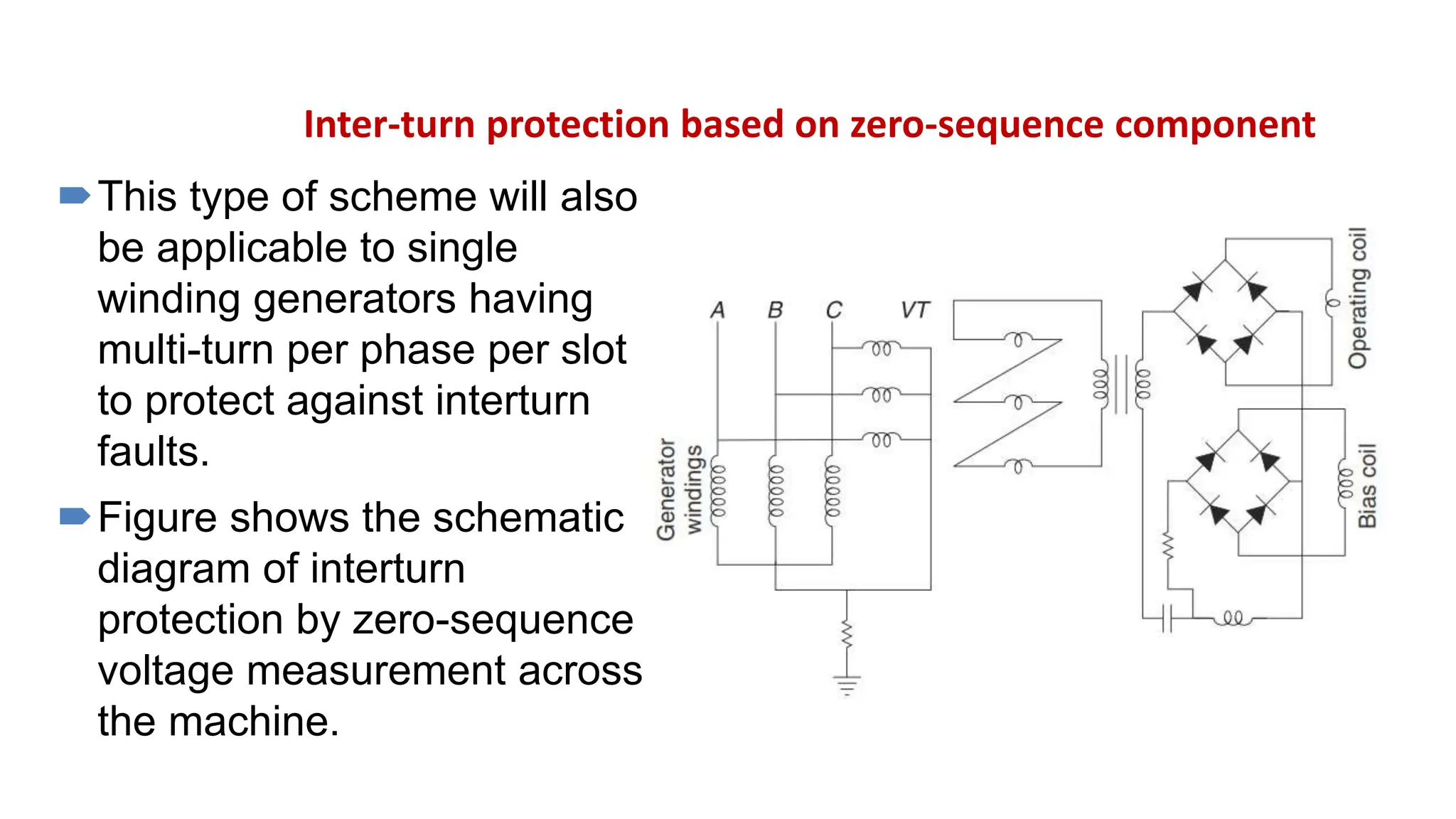
Download to read offline

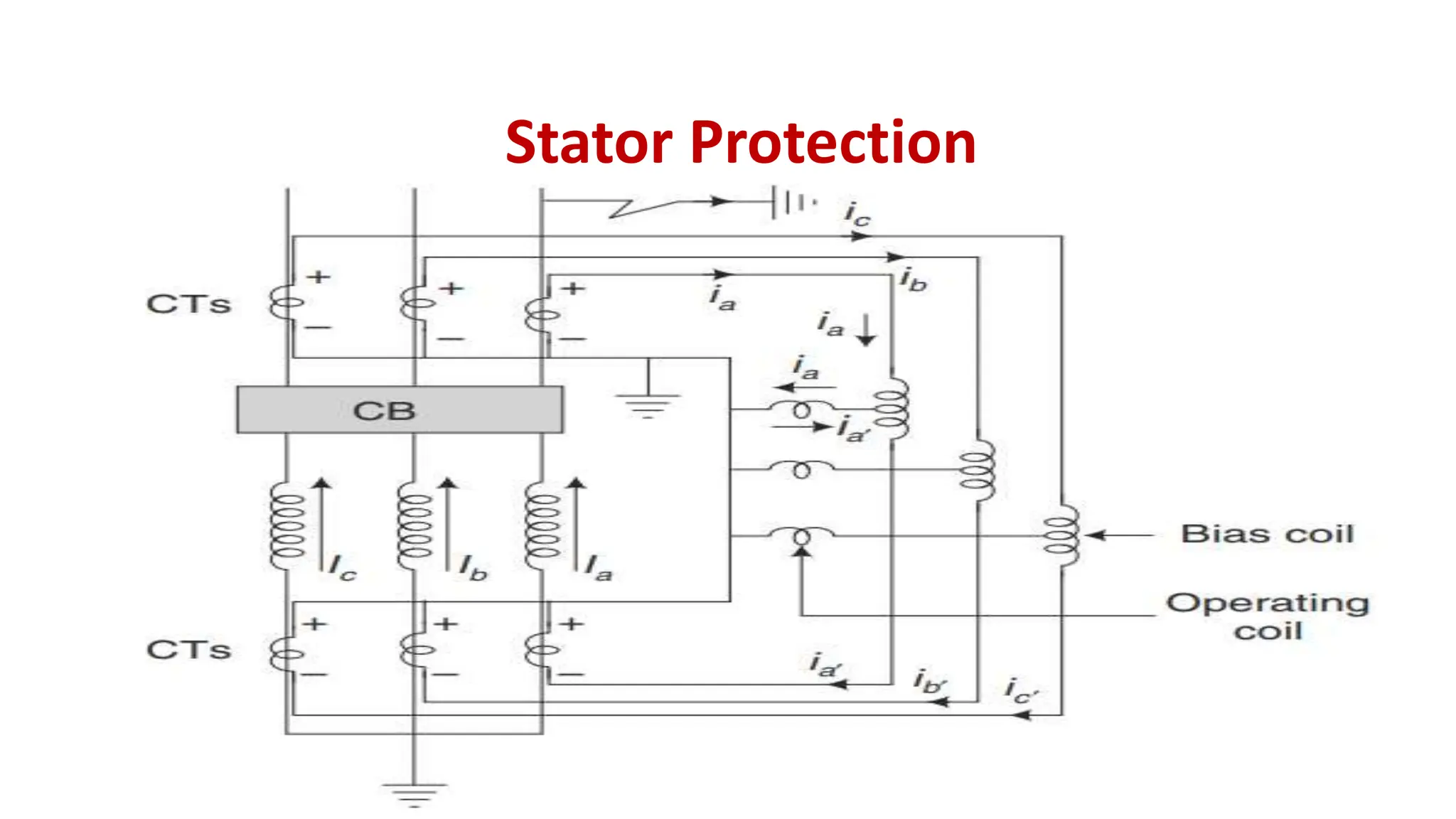
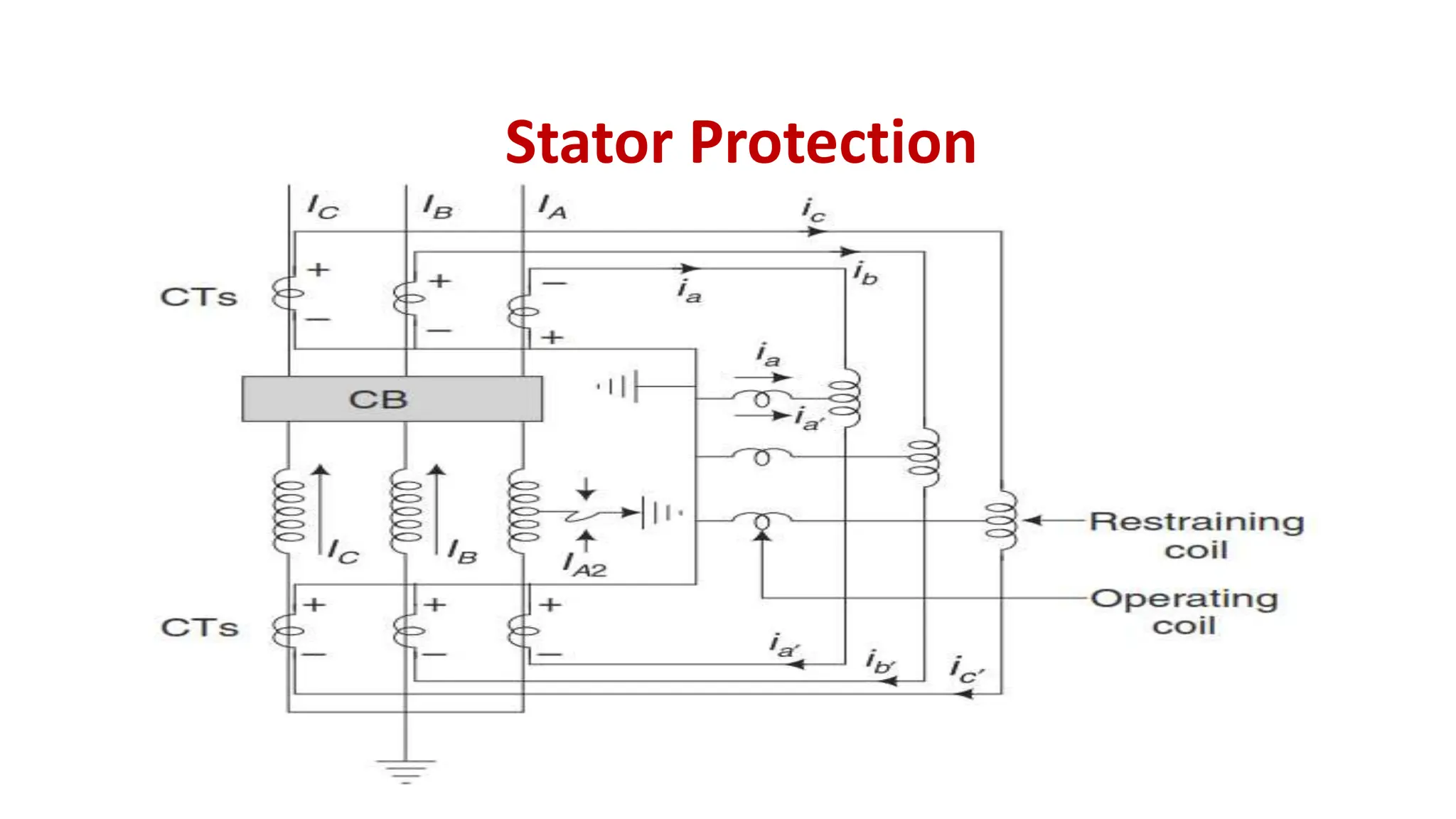
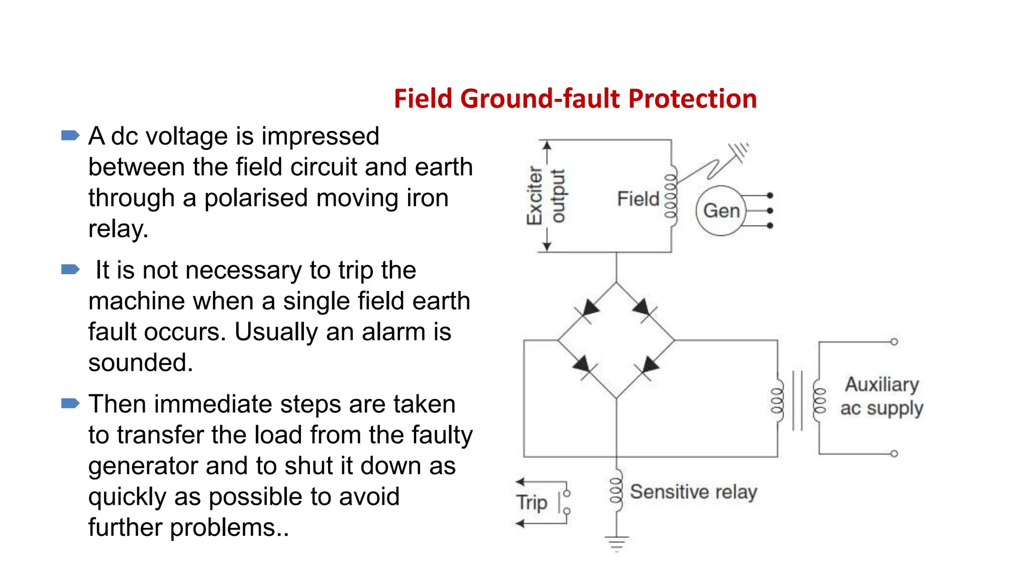

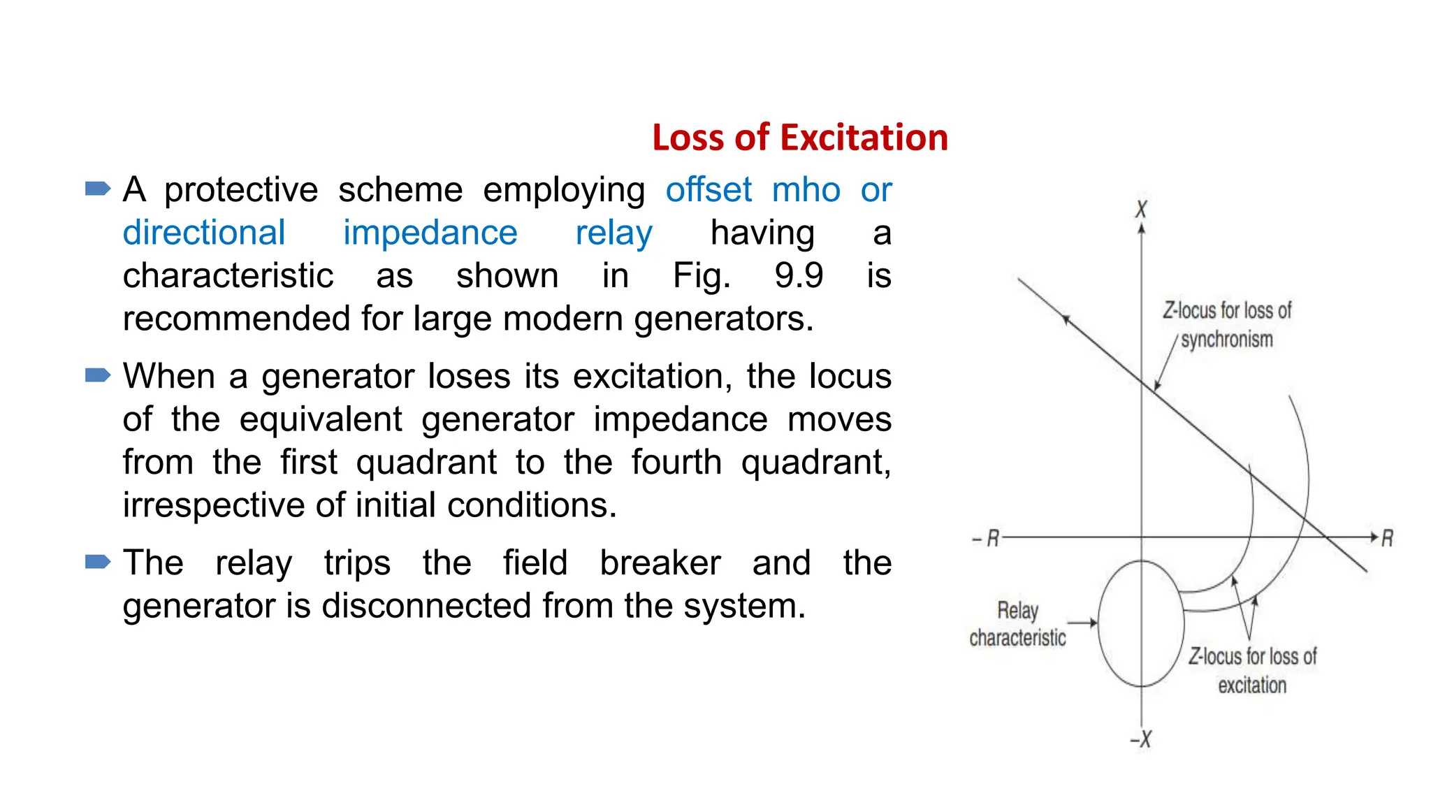


The document details various protection mechanisms for generators above 1 MW, including stator and rotor fault protection, stator overheating protection, and mechanisms against loss of excitation and overspeed. It discusses methods for handling phase-to-phase and phase-to-ground faults, as well as the implications of neutral grounding on protection percentages. Additional considerations addressed include protection against motoring, vibration, and failure of auxiliary systems critical to generator operation, ensuring overall reliability and safety.


