This document provides a diagnostic test report of a 22kV/0.4kV transformer. It includes the results of various tests performed on the transformer such as insulation resistance, magnetic balance, vector group, impedance, winding resistance, and SFRA tests. The document finds that the transformer is in critical condition based on dissolved gas, moisture content, and partial discharge analysis. It recommends taking the transformer out of service, performing oil filtration and retrofitting with new protections before putting it back in service.
![Page8
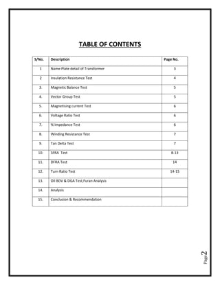
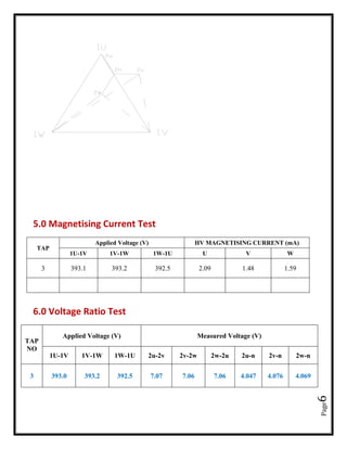
9.0 Tan Delta and Capacitance Measurement:
Oil temp= 22°C RH%= 58.0% K Value – 0.97
Sr.
No
Capacitance
being
measured
Test
Mode
Measured
capacitance
(nF)
Insulation
P.F (%)
Insulatio
n P.F
(%)
Amp.
Temp˚C
Humidity
( RH) %
1 HV-E GST G 1.034 0.317 0.307 21.6 58
2 HV-LV UST Y 2.583 0.532
0.516
21.6 58
3 HV-LV+E GST YG 3.618 0.474
0.459
21.6 58
4 LV-E GST G 6.638 0.564
0.547
21.6 58
5 LV-HV UST Y 2.584 0.525
0.509
21.6 58
6 LV-HV+E GST YG 9.220 0.546
0.529
21.6 58
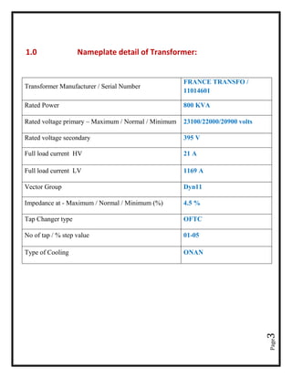
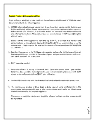
10.0 SFRA ANALYSIS:
1U-1V (LV OPEN)
-20
-30
-40
-50
-60
-70
-80
-90
Magnitude(dB)
100 1 k 10 k 100 k 1 M
Frequency (Hz)
[H1-H2 [open]]](https://image.slidesharecdn.com/trfsamplereport-190309151014/85/TRANSFORMER-SAMPLE-REPORT-DGA-PHYSICAL-CONDITION-8-320.jpg)
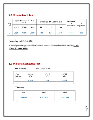
![Page9
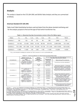
1V-1W(LV OPEN)
1W-1U(LV OPEN)
1U,1V,1W(LV OPEN)
-10
-20
-30
-40
-50
-60
-70
-80
-90
Magnitude(dB)
100 1 k 10 k 100 k 1 M
Frequency (Hz)
[H2-H3 [open]]
-10
-20
-30
-40
-50
-60
-70
-80
-90
Magnitude(dB)
100 1 k 10 k 100 k 1 M
Frequency (Hz)
[H3-H1 [open] (1)]](https://image.slidesharecdn.com/trfsamplereport-190309151014/85/TRANSFORMER-SAMPLE-REPORT-DGA-PHYSICAL-CONDITION-9-320.jpg)
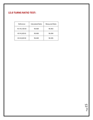
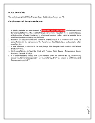
![Page10
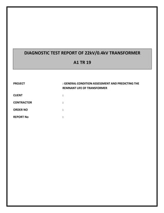
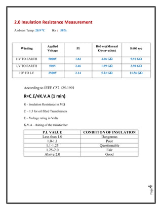
X1-X0
X2-X0
-10
-20
-30
-40
-50
-60
-70
-80
-90
Magnitude(dB)
100 1 k 10 k 100 k 1 M
Frequency (Hz)
[H1-H2 [open]] [H2-H3 [open]] [H3-H1 [open] (1)]
0
-5
-10
-15
-20
Magnitude(dB)
100 1 k 10 k 100 k 1 M
Frequency (Hz)
[X1-X0 [open]]](https://image.slidesharecdn.com/trfsamplereport-190309151014/85/TRANSFORMER-SAMPLE-REPORT-DGA-PHYSICAL-CONDITION-10-320.jpg)
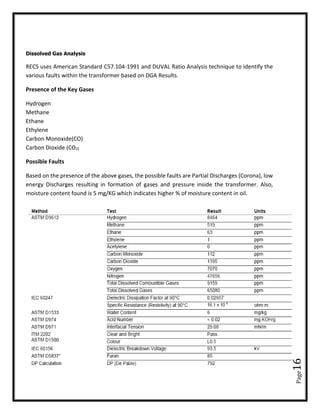
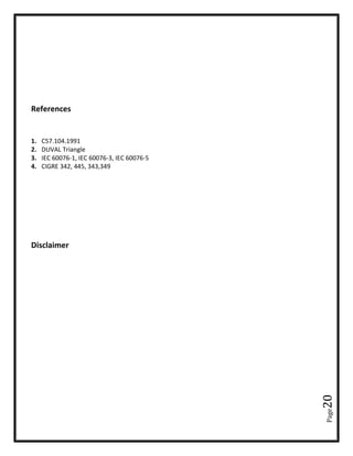
![Page11
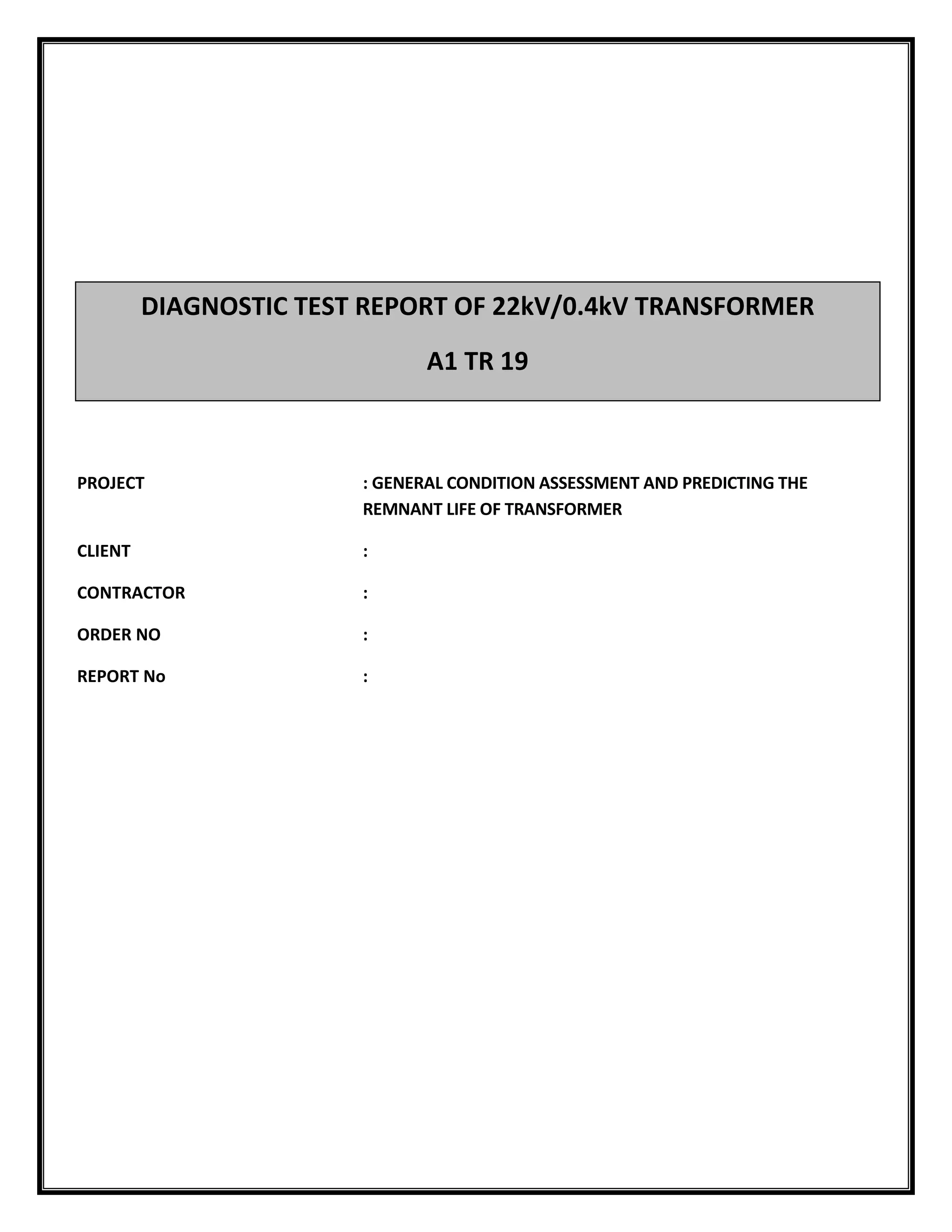
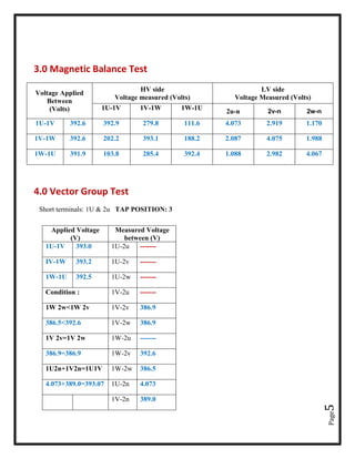
X3-X0
0
-5
-10
-15
-20
Magnitude(dB)
100 1 k 10 k 100 k 1 M
Frequency (Hz)
[X2-X0 [open]]
0
-5
-10
-15
-20
Magnitude(dB)
100 1 k 10 k 100 k 1 M
Frequency (Hz)
[X3-X0 [open]]](https://image.slidesharecdn.com/trfsamplereport-190309151014/85/TRANSFORMER-SAMPLE-REPORT-DGA-PHYSICAL-CONDITION-11-320.jpg)
![Page12
X1-X0,X2-X0,X3-X0
1U-1V (LV SHORT)
1V – 1W(LV SHORT)
0
-5
-10
-15
-20
Magnitude(dB)
100 1 k 10 k 100 k 1 M
Frequency (Hz)
[X1-X0 [open]] [X2-X0 [open]] [X3-X0 [open]]
-10
-20
-30
-40
-50
-60
Magnitude(dB)
100 1 k 10 k 100 k 1 M
Frequency (Hz)
[H1-H2 [short X1-X2-X3]]](https://image.slidesharecdn.com/trfsamplereport-190309151014/85/TRANSFORMER-SAMPLE-REPORT-DGA-PHYSICAL-CONDITION-12-320.jpg)
![Page13
1W-1U (LV SHORT)
1U-1V,1V-1W,1W-1U (LV SHORT)
-10
-20
-30
-40
-50
-60
Magnitude(dB)
100 1 k 10 k 100 k 1 M
Frequency (Hz)
[H2-H3 [short X1-X2-X3]]
-10
-20
-30
-40
-50
-60
Magnitude(dB)
100 1 k 10 k 100 k 1 M
Frequency (Hz)
[H3-H1 [short X1-X2-X3]]](https://image.slidesharecdn.com/trfsamplereport-190309151014/85/TRANSFORMER-SAMPLE-REPORT-DGA-PHYSICAL-CONDITION-13-320.jpg)
![Page14
11.0 DFRA ANALYSIS:
Measured Graphs Vs Frequency (Attached Graphs)
✓ Oil Conductivity
✓ Polarisation Depolaraisation
✓ Tan Delta & Capacitance
✓ Tan Delta
✓ Powerfactor
✓ Impedance
-10
-20
-30
-40
-50
-60
Magnitude(dB)
100 1 k 10 k 100 k 1 M
Frequency (Hz)
[H1-H2 [short X1-X2-X3]] [H2-H3 [short X1-X2-X3]] [H3-H1 [short X1-X2-X3]]](https://image.slidesharecdn.com/trfsamplereport-190309151014/85/TRANSFORMER-SAMPLE-REPORT-DGA-PHYSICAL-CONDITION-14-320.jpg)


![Transformer Repair Workshop Report [EEE]](https://cdn.slidesharecdn.com/ss_thumbnails/transformerrepairworkshopeee-140621072318-phpapp01-thumbnail.jpg?width=640&height=640&fit=bounds)