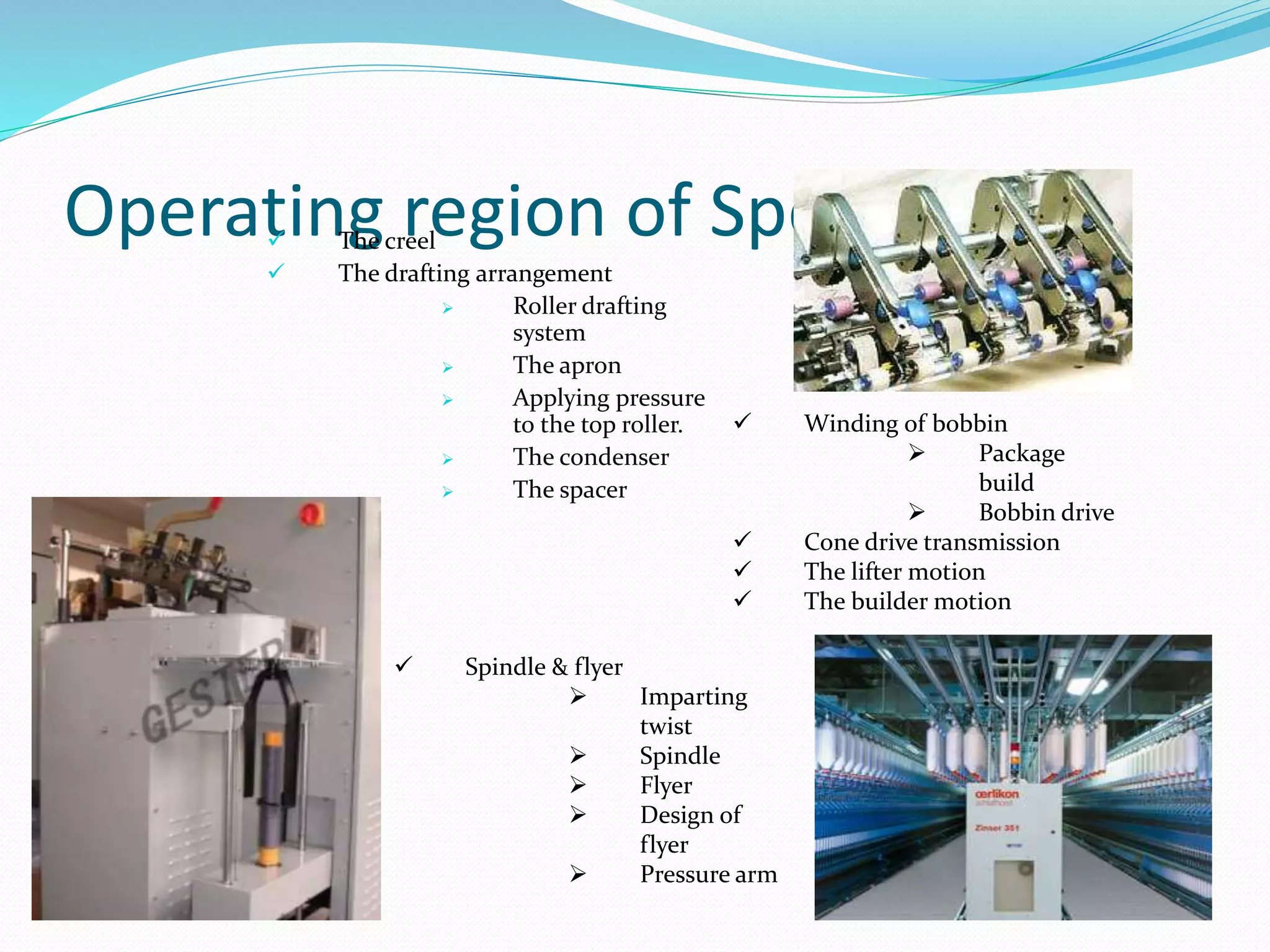
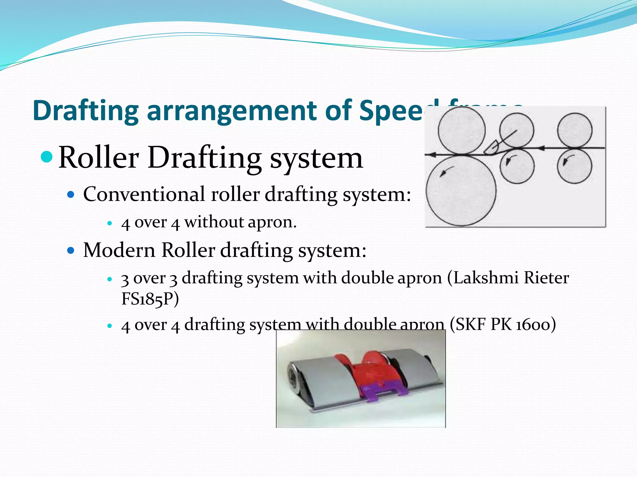
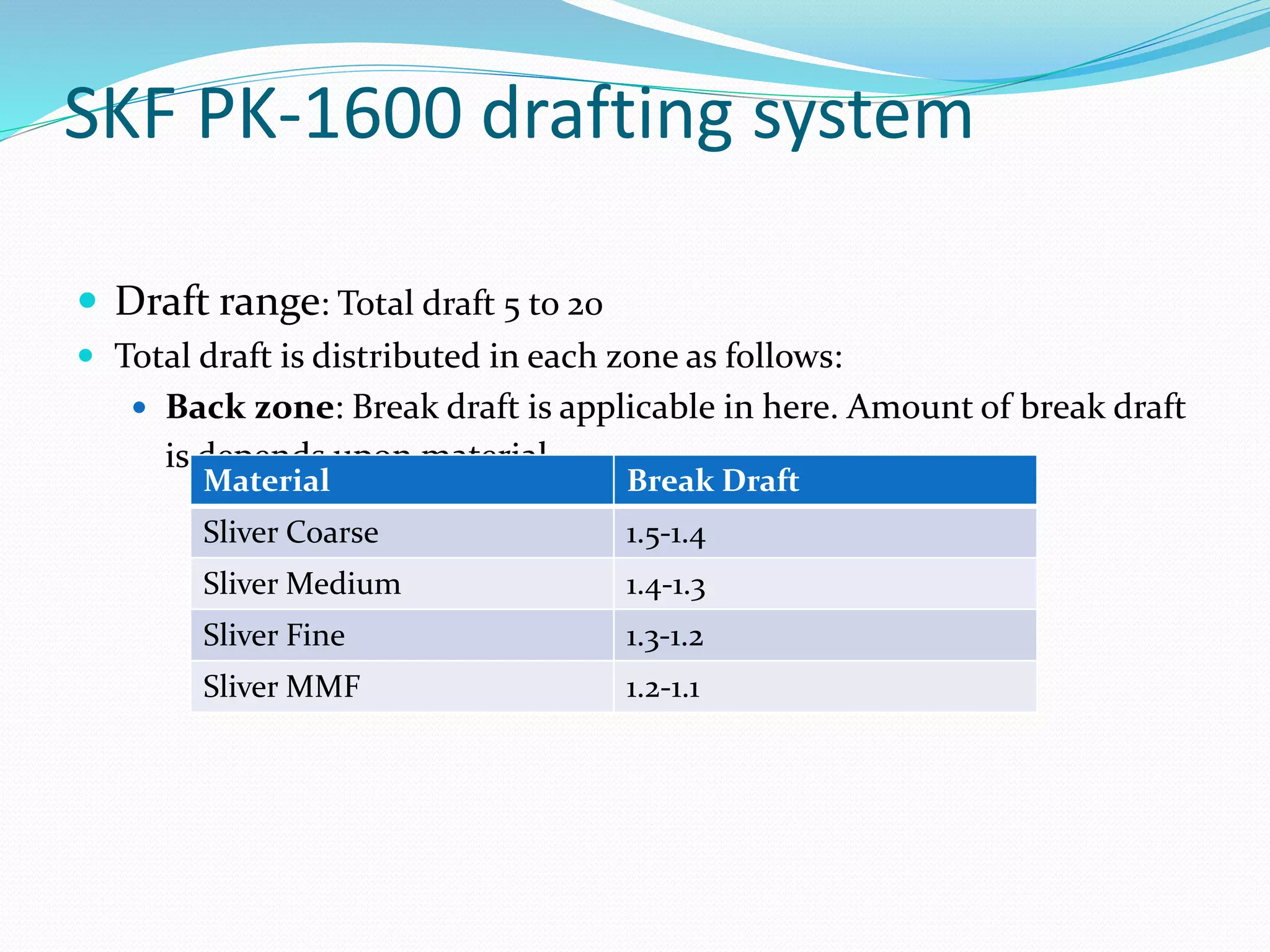
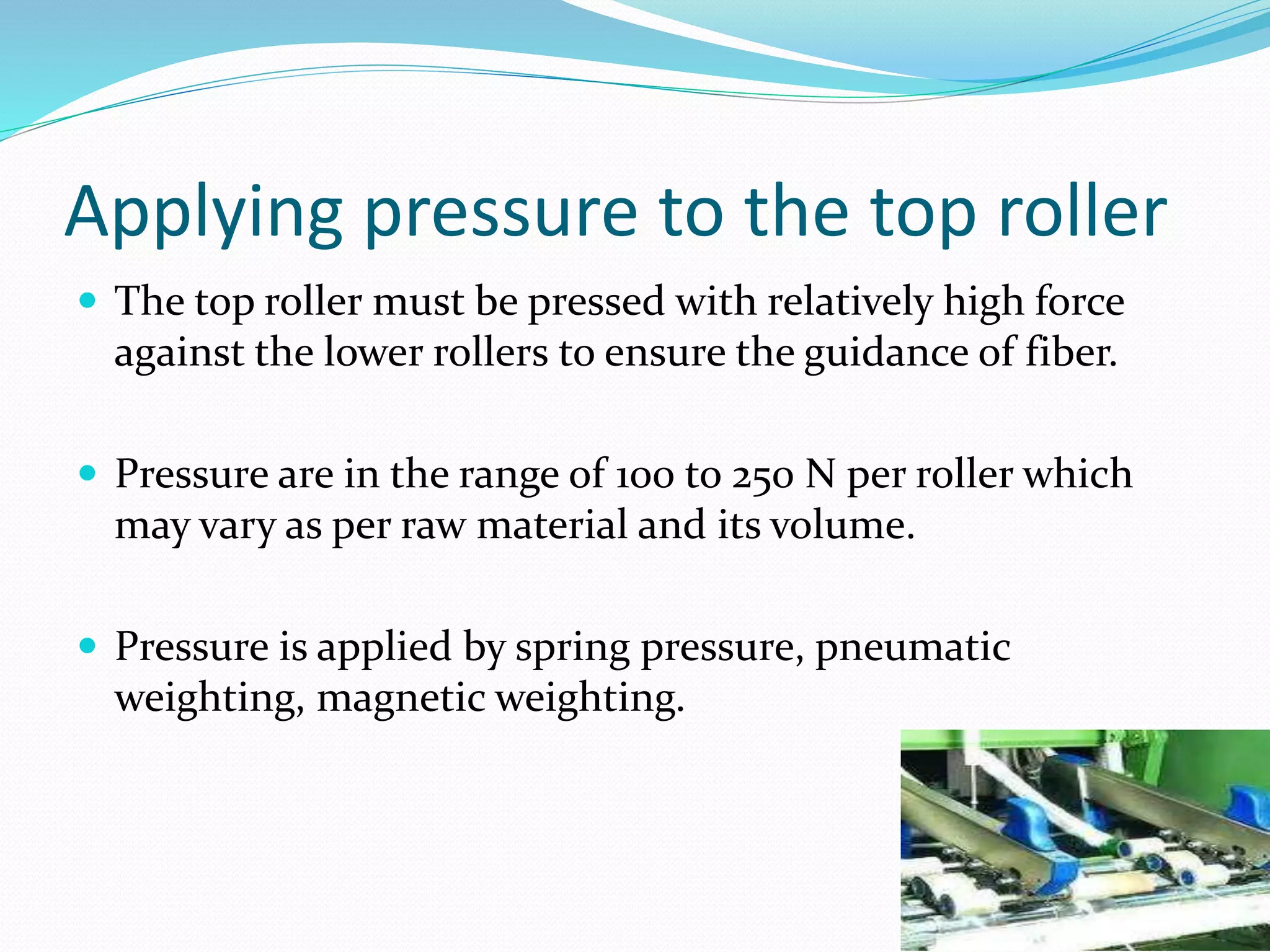
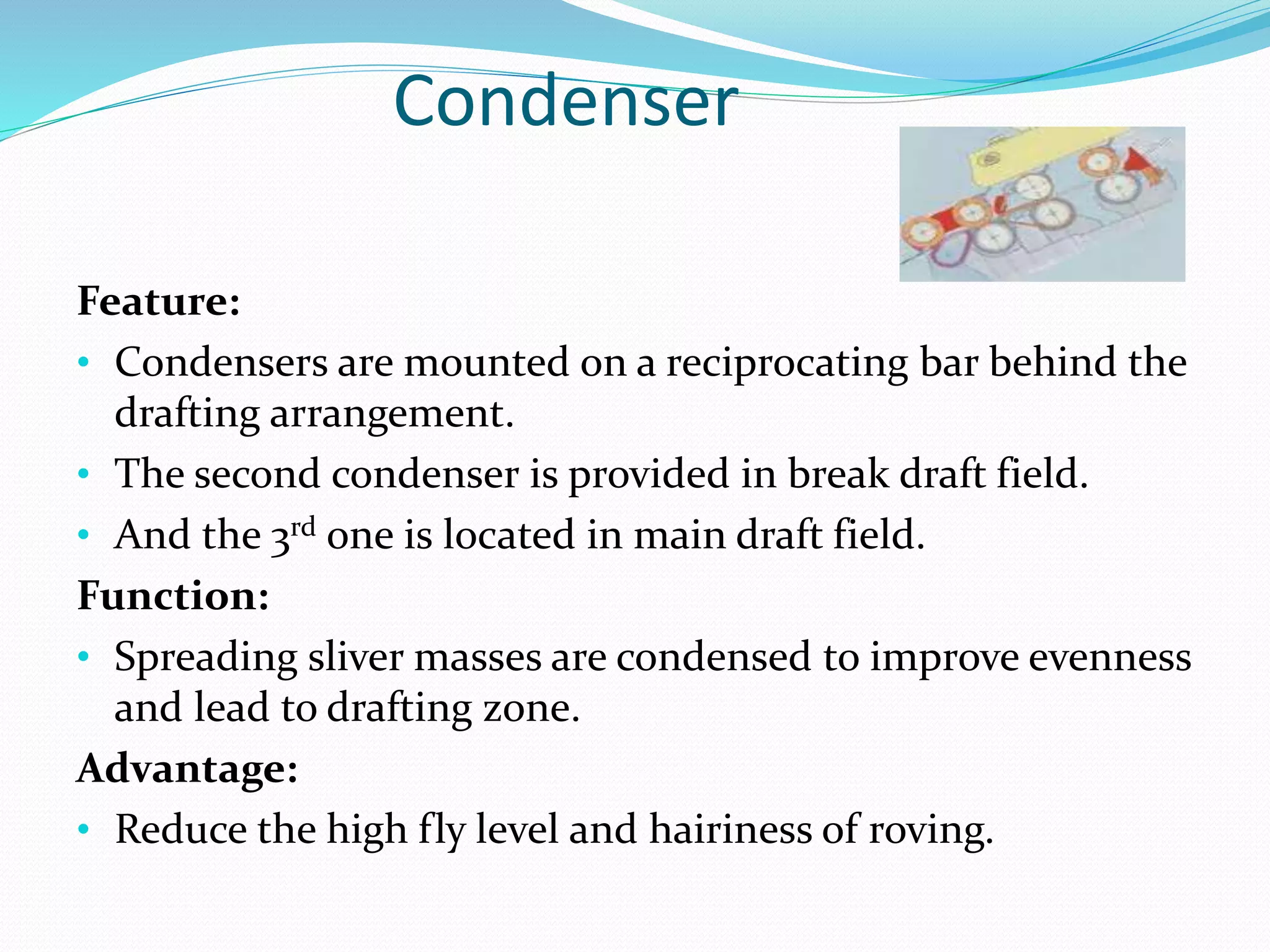
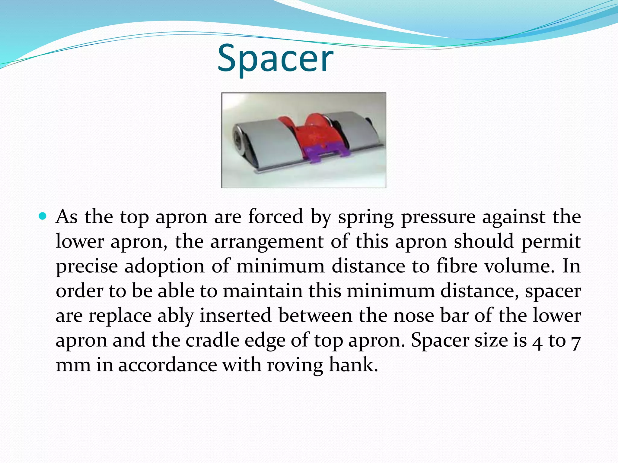
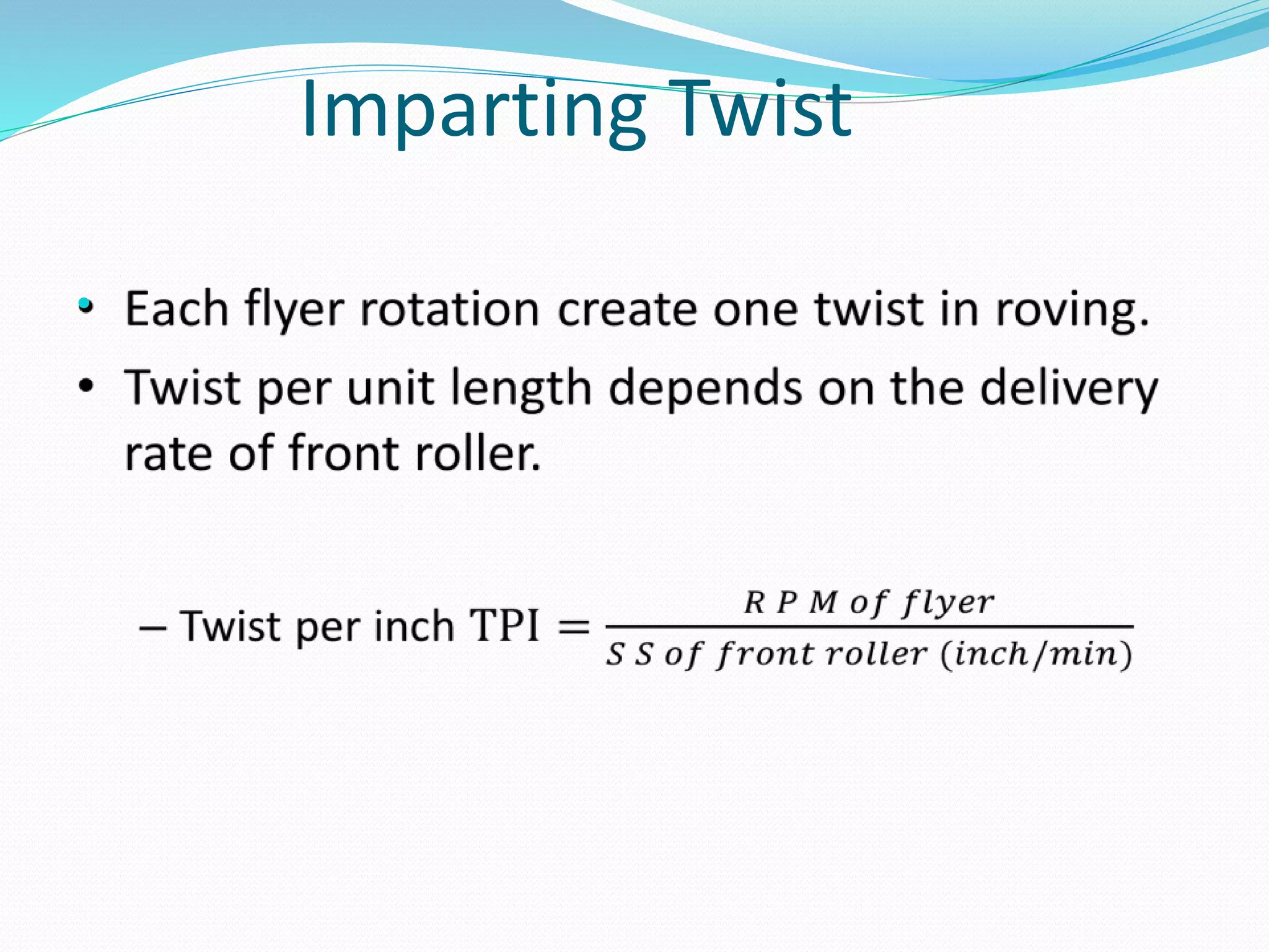
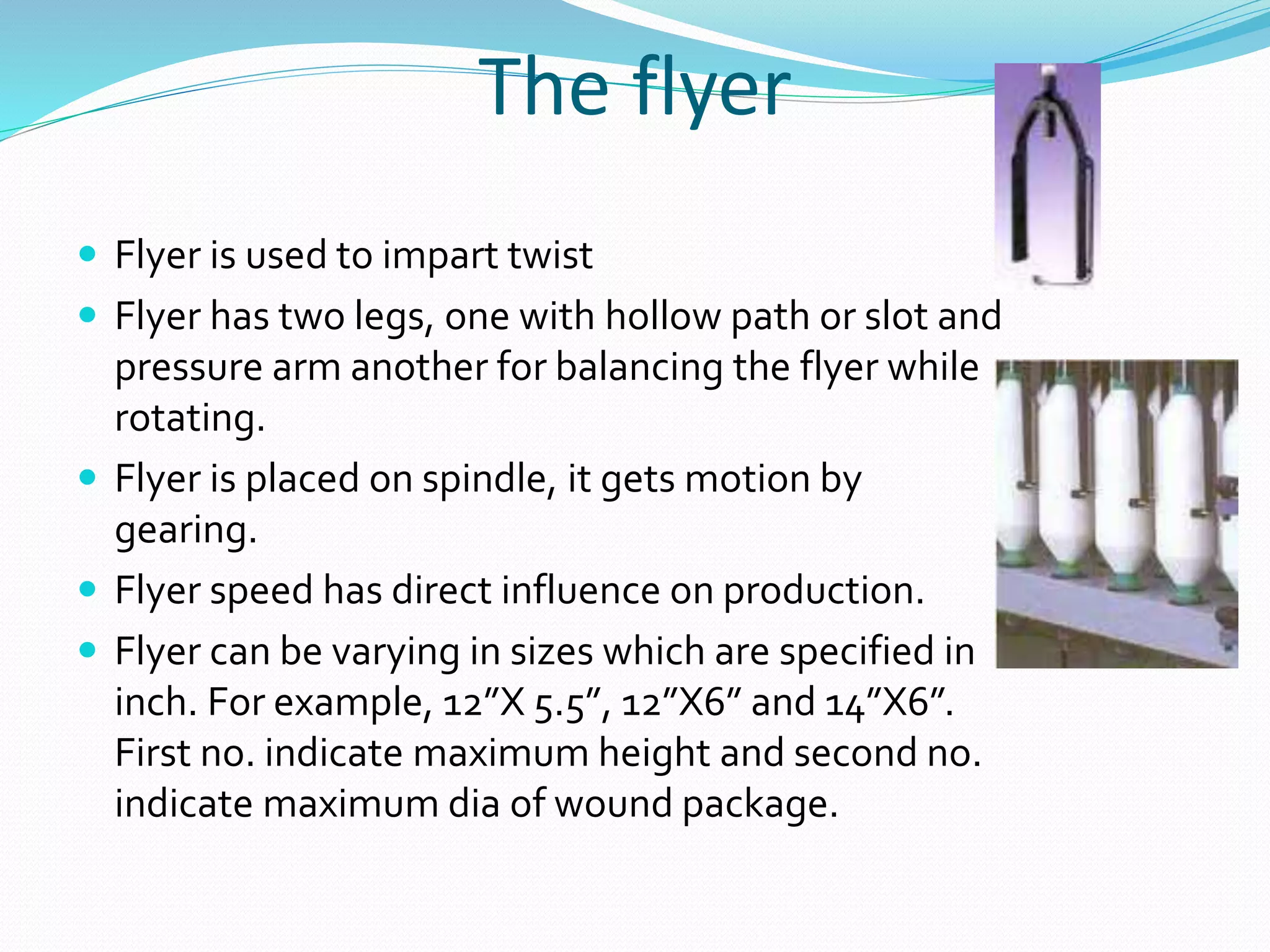
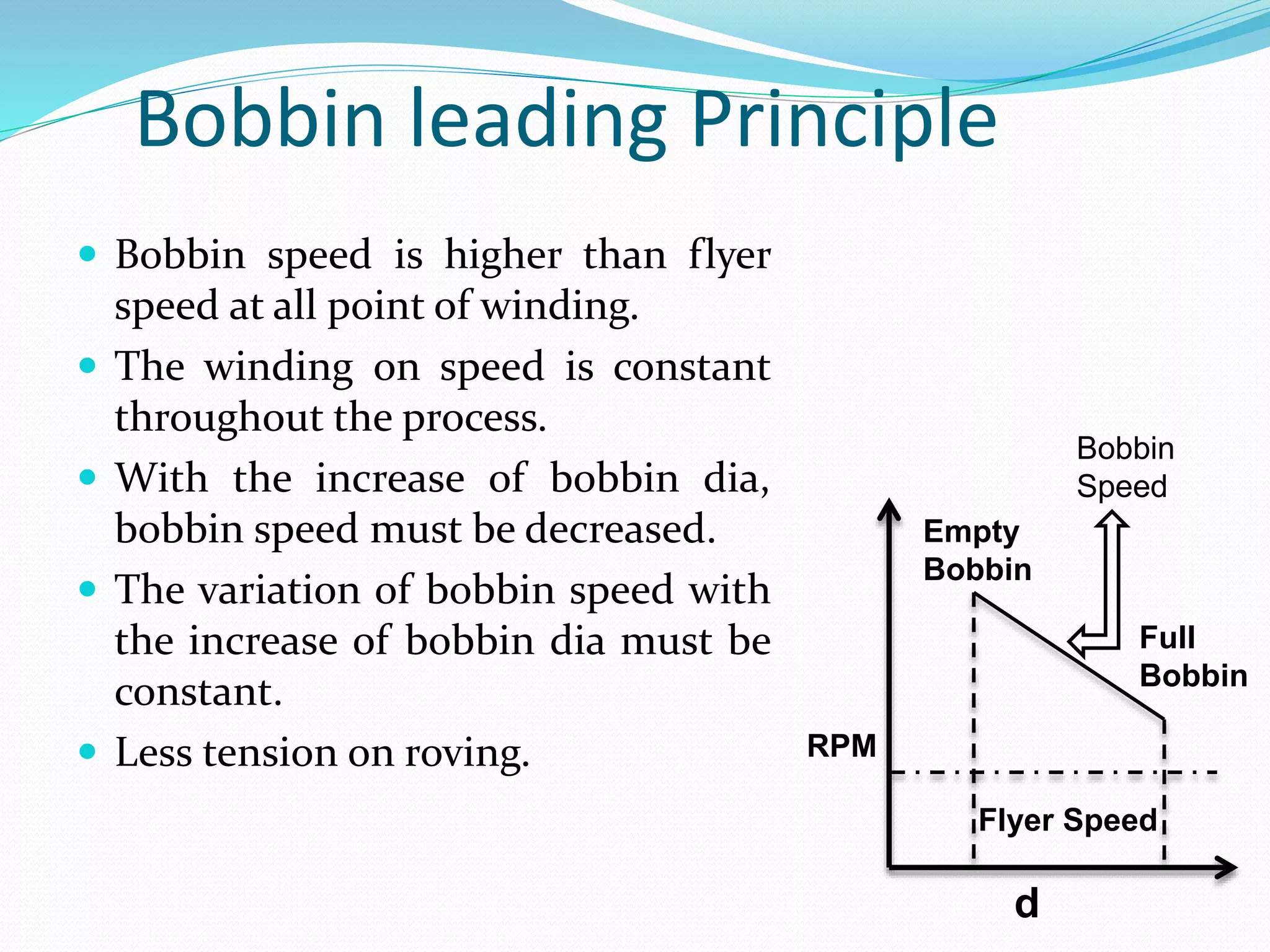
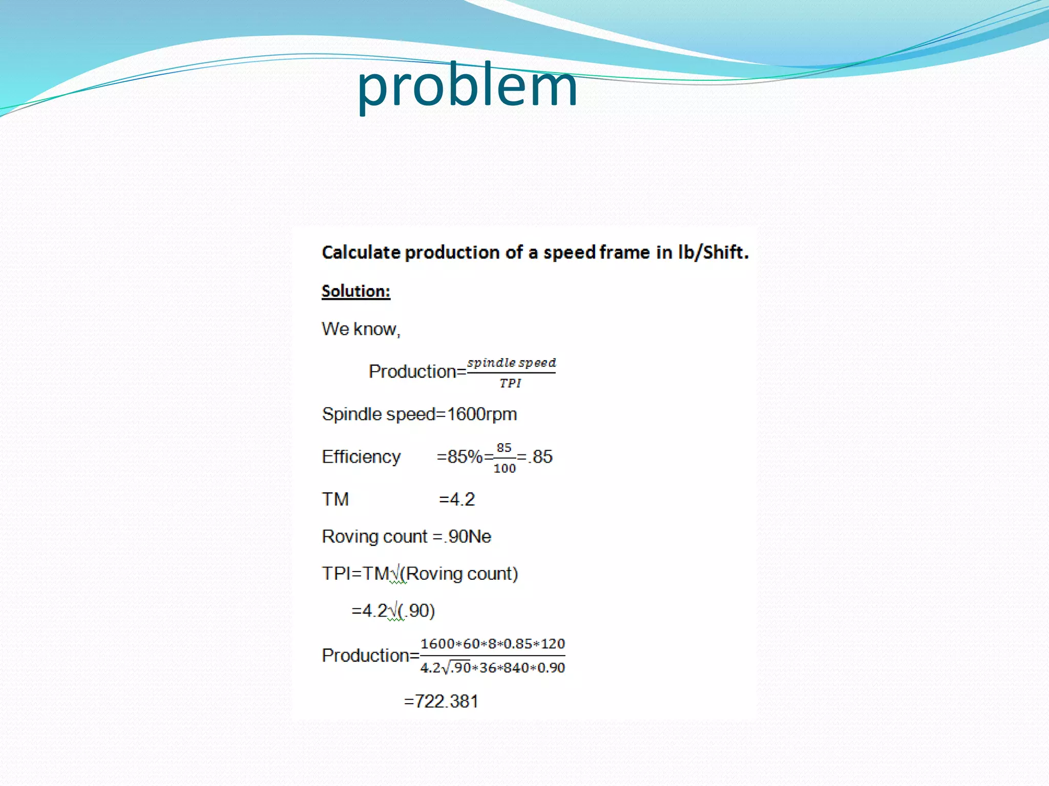
Group Members:
Name ID
Md.Mohit-Ul Alam 131-23-3384
Masum Billah 131-23-3435
Hafeza Islam 131-23-3358
Our presentation topic:
Speed frame
Objectives of speed/roving
frame
 The chief function of roving frame is the attenuation of sliver.
 To draft the sliver to reduce weight per unit length.
 Insertion of protective twist in order to hold the fine strand of
sliver.
 To make conical or tapper shape of the bobbin.
 Wind the twisted roving on to the bobbin.
 Winding of roving into a package that can be transported,
sorted, donned on ring spinning machine.
Q: Why the draw sliver is not
direct used in ring machine ?
ANSWER:
There are two main reasons:
The first reason is related to the required draft. The
draw sliver is to thick, untwist strand that tends to
be hairy and to create fly. The fine twisted roving is
better to this purpose.
The second reason is that draw frame can represent
the worst conceivable mode of transport and
presentation of feed material to the ring spinning
frame.
Main objectives
DRAFTING
TWISTING
WINDING
Main objectives
Operating region of Speed frame The creel
 The drafting arrangement
 Roller drafting
system
 The apron
 Applying pressure
to the top roller.
 The condenser
 The spacer
 Winding of bobbin
 Package
build
 Bobbin drive
 Cone drive transmission
 The lifter motion
 The builder motion
 Spindle & flyer
 Imparting
twist
 Spindle
 Flyer
 Design of
flyer
 Pressure arm
Drafting arrangement of Speed frame
Roller Drafting system
 Conventional roller drafting system:
 4 over 4 without apron.
 Modern Roller drafting system:
 3 over 3 drafting system with double apron (Lakshmi Rieter
FS185P)
 4 over 4 drafting system with double apron (SKF PK 1600)
SKF PK-1600 drafting system
 Draft range: Total draft 5 to 20
 Total draft is distributed in each zone as follows:
 Back zone: Break draft is applicable in here. Amount of break draft
is depends upon material.
Material Break Draft
Sliver Coarse 1.5-1.4
Sliver Medium 1.4-1.3
Sliver Fine 1.3-1.2
Sliver MMF 1.2-1.1
 Middle zone:
 Less amount draft is applicable in here.
 Condenser is used in middle zone to condense sheet like
sliver.
 Front zone:
 Maximum amount of draft is applicable in here. Apron is
used in this zone.
Roller type
 Top rollers are synthetic rubber coated
 Bottom rollers are made of steel
 Front, 3rd and back rollers (bottom) are spiral fluted.
 2nd roller has granulated pin.
The Apron
The upper aprons are short and made either
of leather or more commonly of synthetic
rubbers. They have a thickness of about 1
mm and are held by tensioning device.
The lower aprons are longer and usually
made of leather. They run over the guide
bar, usually known as nose bar, to position
close to the delivery roller.
Function:
The aprons co-operated with each other t
guide and transports the fibers during drafting
and they exert a very significant influence on
the drafting operations.
Applying pressure to the top roller
 The top roller must be pressed with relatively high force
against the lower rollers to ensure the guidance of fiber.
 Pressure are in the range of 100 to 250 N per roller which
may vary as per raw material and its volume.
 Pressure is applied by spring pressure, pneumatic
weighting, magnetic weighting.
Condenser
Feature:
• Condensers are mounted on a reciprocating bar behind the
drafting arrangement.
• The second condenser is provided in break draft field.
• And the 3rd one is located in main draft field.
Function:
• Spreading sliver masses are condensed to improve evenness
and lead to drafting zone.
Advantage:
• Reduce the high fly level and hairiness of roving.
Spacer
 As the top apron are forced by spring pressure against the
lower apron, the arrangement of this apron should permit
precise adoption of minimum distance to fibre volume. In
order to be able to maintain this minimum distance, spacer
are replace ably inserted between the nose bar of the lower
apron and the cradle edge of top apron. Spacer size is 4 to 7
mm in accordance with roving hank.
Imparting Twist
•
The flyer
 Flyer is used to impart twist
 Flyer has two legs, one with hollow path or slot and
pressure arm another for balancing the flyer while
rotating.
 Flyer is placed on spindle, it gets motion by
gearing.
 Flyer speed has direct influence on production.
 Flyer can be varying in sizes which are specified in
inch. For example, 12”X 5.5”, 12”X6” and 14”X6”.
First no. indicate maximum height and second no.
indicate maximum dia of wound package.
Spindle
The spindle is a simply support and drive element for
the flyer,without any axuilary function. It is a long steel
shaft mounted at it’s lower end in a bearing.
 Types of spindle:
 01.mounted mounted.
 02.closed mounted.
 03.top mounted.
Pressure Arm
 A steel yoke attached to the lower end of hollow flyer leg is
called pressure arm.
 The roving is wrapped 2 or 3 times around the yoke.
 The no. of turn determine the roving tension. For higher
tension, a hard compact package is obtained and if it is too
high false draft or roving breakage can be caused.
 Therefore, the no. of wrap depends upon material and twist
level.
Winding Principle
 Bobbin leading principle (For cotton spinning)
 Flyer leading principle (For jute spinning)
Bobbin leading Principle
 Bobbin speed is higher than flyer
speed at all point of winding.
 The winding on speed is constant
throughout the process.
 With the increase of bobbin dia,
bobbin speed must be decreased.
 The variation of bobbin speed with
the increase of bobbin dia must be
constant.
 Less tension on roving. RPM
d
Empty
Bobbin
Full
Bobbin
Bobbin
Speed
Flyer Speed
Faults of speed frame
 01/ Irregular Roving.
 02/ Roving breakage .
 03/ Sliver breakage.
 04/ Roller lapping.
 05/ Unequal tapering .
 06/ Hard roving bobbin.
 07/ Ridgy bobbin .
 08/Thicks thin place.
M/C Faults:
i. Fluction of power
ii. Ununiform rotation of flyer
iii. Using of damaged flyer
iv. Damage top roller
v. Damage apron.
problem

Study on the Automation in Speed Frame

  • 2.
    Group Members: Name ID Md.Mohit-UlAlam 131-23-3384 Masum Billah 131-23-3435 Hafeza Islam 131-23-3358
  • 3.
  • 4.
  • 5.
    Objectives of speed/roving frame The chief function of roving frame is the attenuation of sliver.  To draft the sliver to reduce weight per unit length.  Insertion of protective twist in order to hold the fine strand of sliver.  To make conical or tapper shape of the bobbin.  Wind the twisted roving on to the bobbin.  Winding of roving into a package that can be transported, sorted, donned on ring spinning machine.
  • 6.
    Q: Why thedraw sliver is not direct used in ring machine ?
  • 7.
    ANSWER: There are twomain reasons: The first reason is related to the required draft. The draw sliver is to thick, untwist strand that tends to be hairy and to create fly. The fine twisted roving is better to this purpose. The second reason is that draw frame can represent the worst conceivable mode of transport and presentation of feed material to the ring spinning frame.
  • 8.
  • 9.
    Operating region ofSpeed frame The creel  The drafting arrangement  Roller drafting system  The apron  Applying pressure to the top roller.  The condenser  The spacer  Winding of bobbin  Package build  Bobbin drive  Cone drive transmission  The lifter motion  The builder motion  Spindle & flyer  Imparting twist  Spindle  Flyer  Design of flyer  Pressure arm
  • 10.
    Drafting arrangement ofSpeed frame Roller Drafting system  Conventional roller drafting system:  4 over 4 without apron.  Modern Roller drafting system:  3 over 3 drafting system with double apron (Lakshmi Rieter FS185P)  4 over 4 drafting system with double apron (SKF PK 1600)
  • 11.
    SKF PK-1600 draftingsystem  Draft range: Total draft 5 to 20  Total draft is distributed in each zone as follows:  Back zone: Break draft is applicable in here. Amount of break draft is depends upon material. Material Break Draft Sliver Coarse 1.5-1.4 Sliver Medium 1.4-1.3 Sliver Fine 1.3-1.2 Sliver MMF 1.2-1.1
  • 12.
     Middle zone: Less amount draft is applicable in here.  Condenser is used in middle zone to condense sheet like sliver.  Front zone:  Maximum amount of draft is applicable in here. Apron is used in this zone.
  • 14.
    Roller type  Toprollers are synthetic rubber coated  Bottom rollers are made of steel  Front, 3rd and back rollers (bottom) are spiral fluted.  2nd roller has granulated pin.
  • 15.
    The Apron The upperaprons are short and made either of leather or more commonly of synthetic rubbers. They have a thickness of about 1 mm and are held by tensioning device. The lower aprons are longer and usually made of leather. They run over the guide bar, usually known as nose bar, to position close to the delivery roller. Function: The aprons co-operated with each other t guide and transports the fibers during drafting and they exert a very significant influence on the drafting operations.
  • 16.
    Applying pressure tothe top roller  The top roller must be pressed with relatively high force against the lower rollers to ensure the guidance of fiber.  Pressure are in the range of 100 to 250 N per roller which may vary as per raw material and its volume.  Pressure is applied by spring pressure, pneumatic weighting, magnetic weighting.
  • 17.
    Condenser Feature: • Condensers aremounted on a reciprocating bar behind the drafting arrangement. • The second condenser is provided in break draft field. • And the 3rd one is located in main draft field. Function: • Spreading sliver masses are condensed to improve evenness and lead to drafting zone. Advantage: • Reduce the high fly level and hairiness of roving.
  • 18.
    Spacer  As thetop apron are forced by spring pressure against the lower apron, the arrangement of this apron should permit precise adoption of minimum distance to fibre volume. In order to be able to maintain this minimum distance, spacer are replace ably inserted between the nose bar of the lower apron and the cradle edge of top apron. Spacer size is 4 to 7 mm in accordance with roving hank.
  • 19.
  • 20.
    The flyer  Flyeris used to impart twist  Flyer has two legs, one with hollow path or slot and pressure arm another for balancing the flyer while rotating.  Flyer is placed on spindle, it gets motion by gearing.  Flyer speed has direct influence on production.  Flyer can be varying in sizes which are specified in inch. For example, 12”X 5.5”, 12”X6” and 14”X6”. First no. indicate maximum height and second no. indicate maximum dia of wound package.
  • 21.
    Spindle The spindle isa simply support and drive element for the flyer,without any axuilary function. It is a long steel shaft mounted at it’s lower end in a bearing.  Types of spindle:  01.mounted mounted.  02.closed mounted.  03.top mounted.
  • 22.
    Pressure Arm  Asteel yoke attached to the lower end of hollow flyer leg is called pressure arm.  The roving is wrapped 2 or 3 times around the yoke.  The no. of turn determine the roving tension. For higher tension, a hard compact package is obtained and if it is too high false draft or roving breakage can be caused.  Therefore, the no. of wrap depends upon material and twist level.
  • 23.
    Winding Principle  Bobbinleading principle (For cotton spinning)  Flyer leading principle (For jute spinning)
  • 24.
    Bobbin leading Principle Bobbin speed is higher than flyer speed at all point of winding.  The winding on speed is constant throughout the process.  With the increase of bobbin dia, bobbin speed must be decreased.  The variation of bobbin speed with the increase of bobbin dia must be constant.  Less tension on roving. RPM d Empty Bobbin Full Bobbin Bobbin Speed Flyer Speed
  • 25.
    Faults of speedframe  01/ Irregular Roving.  02/ Roving breakage .  03/ Sliver breakage.  04/ Roller lapping.  05/ Unequal tapering .  06/ Hard roving bobbin.  07/ Ridgy bobbin .  08/Thicks thin place. M/C Faults: i. Fluction of power ii. Ununiform rotation of flyer iii. Using of damaged flyer iv. Damage top roller v. Damage apron.
  • 26.