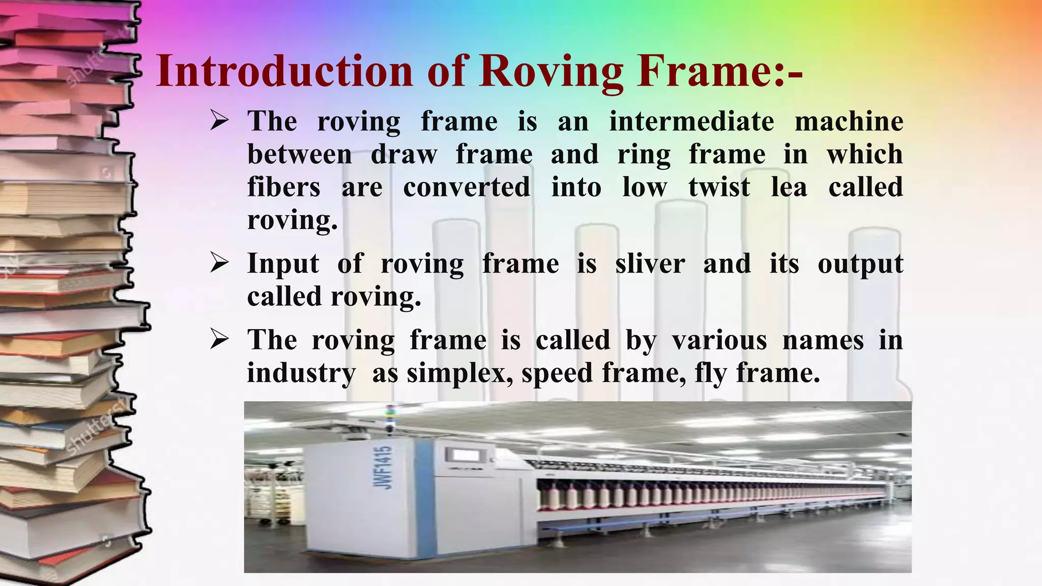
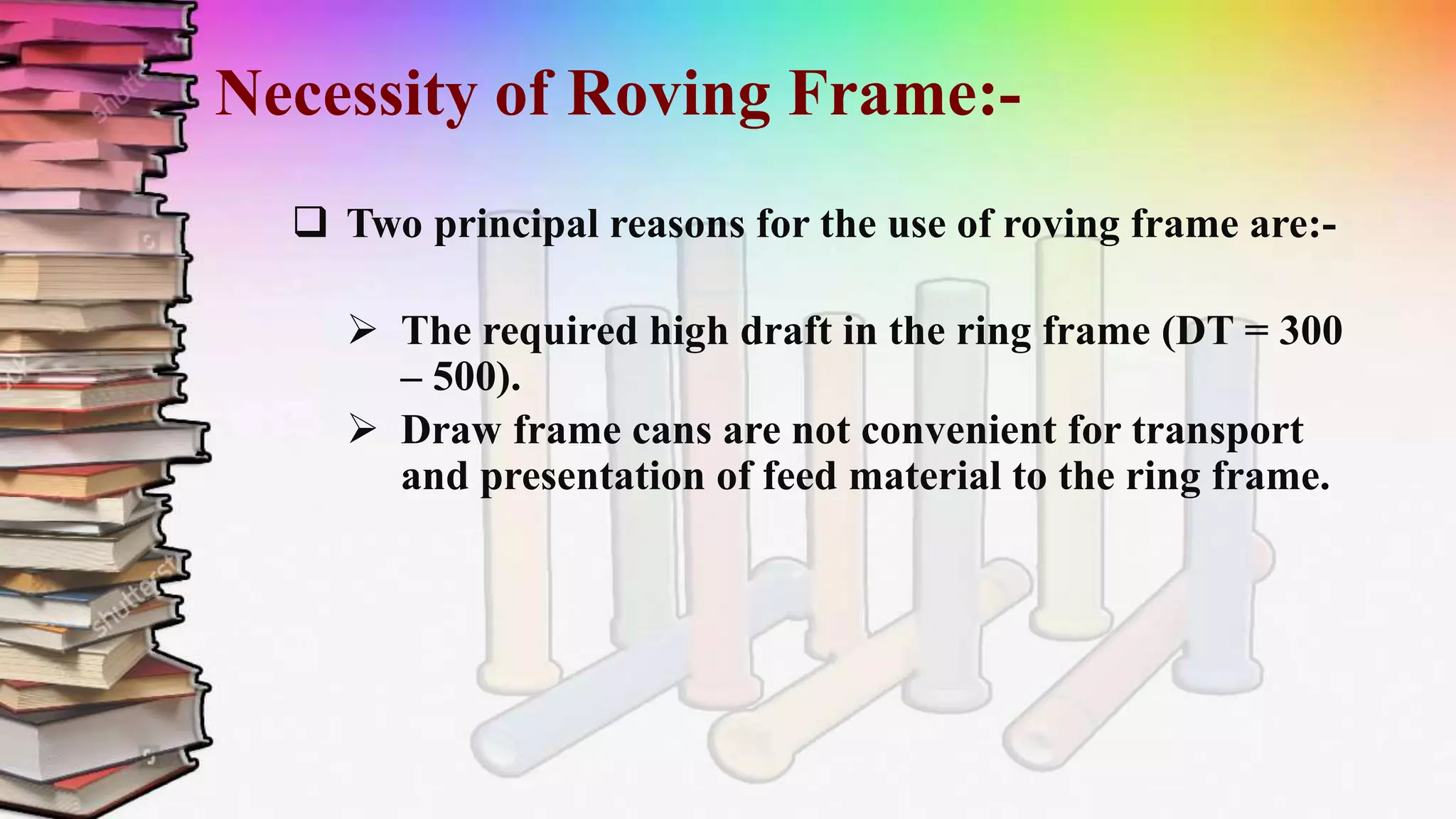
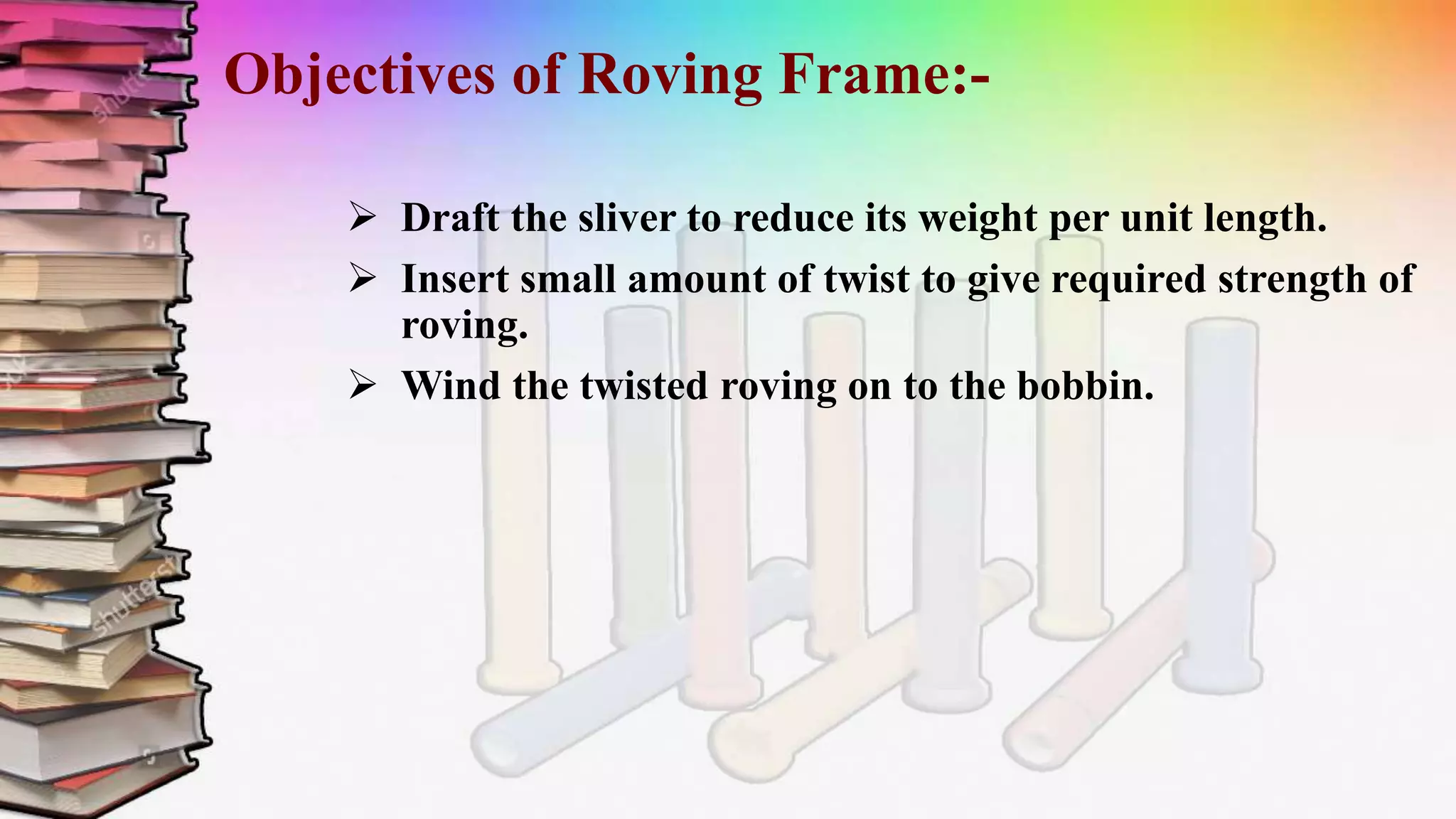
TOPIC:-
PRESENTED BY:-
Study on Roving Frame.
Luqman Tariq (15-NTU-0062)
Hafiz Abdul Basit (15-NTU-0042)
Hafiz Syed Ahmad (15-NTU-0046)
Ghazanfar Ali (15-NTU-0039)
Introduction of Roving Frame:-
 The roving frame is an intermediate machine
between draw frame and ring frame in which
fibers are converted into low twist lea called
roving.
 Input of roving frame is sliver and its output
called roving.
 The roving frame is called by various names in
industry as simplex, speed frame, fly frame.
Necessity of Roving Frame:-
 Two principal reasons for the use of roving frame are:-
 The required high draft in the ring frame (DT = 300
– 500).
 Draw frame cans are not convenient for transport
and presentation of feed material to the ring frame.
Objectives of Roving Frame:-
 Draft the sliver to reduce its weight per unit length.
 Insert small amount of twist to give required strength of
roving.
 Wind the twisted roving on to the bobbin.
Operations Involved in Roving Frame:-
Creeling.
Drafting.
Twisting.
Laying.
Winding.
Building.
Doffing.
Advantages of Roving Frame:-
Occupied less volume w.r.t. weight
 Handling is easy
Transportation is easy
Stability increases
Parts of Roving Frame
&
its Function.
Creel:-
 Creel is used to guide the sliver. Creel portion is present
above the can.
 Creel help the sliver on their way to the drafting
arrangements without any disturbance
Guide Roller:-
Guide roller are used to guide the sliver.
Sliver Guide:-
 Its also used to guide the sliver.
Condenser:-
 Condenser are used to condensing/pressing the sliver.
 The purpose of condenser is to bring the fiber strand back
together again.
Pressure Arm:-
Pressure arm is use to give pressure onto the
material.
Back Pair of Drafting Roller:-
The drafting start from these roller.
The back roller are negatively driven.
The bottom pair roller the positively driven.
The diameter of back roller are 28mm.
Middle pair of Drafting Roller:-
The main drafting occur in this region.
The speed is greater than back pair of roller.
The diameter of these roller are 28mm.
Front pair of Drafting Roller:-
The further drafting occur in this region.
The speed of these pair of roller is greater than the
middle pair of roller.
The diameter of these rollers are 28mm.
Cradle:-
 Cradle are used to give proper tension to the
upper and bottom rollers. For proper
guidance of material.
Spacer:-
 The main function of distance clip are to maintain
sufficient distance between top and bottom aprons to
attenuate the strand properly.
Aprons:-
 The aprons co-operate each other to guide and
transport the fiber during drafting.
Drafting Pressure:-
 The top roller must be pressed with relatively high force
against the lower roller to ensure guidance of the fiber.
 Pressure in the range 100N to250N-300N per roller and
they are dependent upon raw material and volume.
Rubber Cord:-
 Cord are made of synthetic rubber and are mounted
on upper rollers.
Flyer:-
 The flyer insert twist; each flyer rotation create one turn in
the roving. Twist per unit length of roving depend upon the
delivery rate.
Presser Arm:-
 The arm has to guide the roving from the exit of the
flyer leg to the package.
Spindle:-
 The spindle is steel rod of circular cross section with its dia
reduce at the top.
 The slot in which the flyer pin is mounted.
 The diameter of spindle also reduce at the bottom and takes
shape of tapered cone.
 Angle of tapered is 80-90 degree.
Roving Bobbins:-
Principle
of
Roving
Drafting Principle:-
Drafting zone must be inclined.
Inclined zone prevent Breakage of fibers.
Fiber become straightened ,Compact and
arranged here.
Twisting Principle:-
One end of material is gripped and other end rotated.
Twist measure in TPI.
TPI=
speed of flyer
Surface speed of front roller
Winding Principle:-
 Flyer Lead winding system.
 Bobbin lead winging system.
Flyer lead winding system:-
 Speed of flyer is high than Bobbin speed.
 Use for long staple fiber.
Bobbin lead winding system:-
Bobbin speed is higher than.
Used for short fiber.
Surface speed= πDN
RPM of bobbin reduced after every layer
Surface speed of bobbin remain constant
Comparison
of different
Roving
Machines
Manufacturer:-
 Rieter - Switzerland (F 15, F 35 etc).
 Toyota - Japan (FL-16, FL-100).
 Lakhshmi Machinery Works India.
 China Textile Machinery Works.
 Marzoli - Itali etc.
Features of (FL-15, FL-35):-
 Upto 160 spindles.
 Available for 6” or 7” bobbins.
 Touch screen operator panel with 10” display.
 Individual drivers for flyer and spindle.
Toyota:- (Comparison)
FL-16
Model of 1985.
No. of spindle are 120.
Cradle radius
31.5*40mm.
Size of feeding can
20”*52”.
Fiber type cotton,
synthetic, blended.
Total draft 332 mm.
FL-100
Model of 1996.
No. of spindle are 144.
Cradle radius
34.5*40mm.
Size of feeding can
20”*45”.
Fiber type combed or
carded.
Total draft 348 mm.
Lakhshmi:- (LF-4200)
Spindle upto 200.
Spindle speed upto 1500 rpm.
Auto doffer with provision for bobbin
transport system.
Automatic roving tension controller.
Drafting system 4 over 4 over 3 over 3.
Lakhshmi:- (LF-1400)
Flyer speed upto 1400 rpm.
Top and bottom clearer driver with suction.
Number of spindle upto 144.
Flexibility in drafting system.
Delivery rate 40m/min.
Lakhshmi:- (LF-1660)
Suspended flyer.
Servo bobbin build.
Higher delivery rate.
Delivery rate 50 m/min.
Recently development in Roving Machine:-
Higher Flyer Speed.
Roving stop motion.
Electronic driven system.
Blow apparatus.
CCD sensor.
ANY
Roving presentation

Roving presentation

  • 2.
    TOPIC:- PRESENTED BY:- Study onRoving Frame. Luqman Tariq (15-NTU-0062) Hafiz Abdul Basit (15-NTU-0042) Hafiz Syed Ahmad (15-NTU-0046) Ghazanfar Ali (15-NTU-0039)
  • 3.
    Introduction of RovingFrame:-  The roving frame is an intermediate machine between draw frame and ring frame in which fibers are converted into low twist lea called roving.  Input of roving frame is sliver and its output called roving.  The roving frame is called by various names in industry as simplex, speed frame, fly frame.
  • 4.
    Necessity of RovingFrame:-  Two principal reasons for the use of roving frame are:-  The required high draft in the ring frame (DT = 300 – 500).  Draw frame cans are not convenient for transport and presentation of feed material to the ring frame.
  • 5.
    Objectives of RovingFrame:-  Draft the sliver to reduce its weight per unit length.  Insert small amount of twist to give required strength of roving.  Wind the twisted roving on to the bobbin.
  • 6.
    Operations Involved inRoving Frame:- Creeling. Drafting. Twisting. Laying. Winding. Building. Doffing.
  • 7.
    Advantages of RovingFrame:- Occupied less volume w.r.t. weight  Handling is easy Transportation is easy Stability increases
  • 8.
    Parts of RovingFrame & its Function.
  • 9.
    Creel:-  Creel isused to guide the sliver. Creel portion is present above the can.  Creel help the sliver on their way to the drafting arrangements without any disturbance
  • 10.
    Guide Roller:- Guide rollerare used to guide the sliver.
  • 11.
    Sliver Guide:-  Itsalso used to guide the sliver.
  • 12.
    Condenser:-  Condenser areused to condensing/pressing the sliver.  The purpose of condenser is to bring the fiber strand back together again.
  • 13.
    Pressure Arm:- Pressure armis use to give pressure onto the material.
  • 14.
    Back Pair ofDrafting Roller:- The drafting start from these roller. The back roller are negatively driven. The bottom pair roller the positively driven. The diameter of back roller are 28mm.
  • 15.
    Middle pair ofDrafting Roller:- The main drafting occur in this region. The speed is greater than back pair of roller. The diameter of these roller are 28mm.
  • 16.
    Front pair ofDrafting Roller:- The further drafting occur in this region. The speed of these pair of roller is greater than the middle pair of roller. The diameter of these rollers are 28mm.
  • 17.
    Cradle:-  Cradle areused to give proper tension to the upper and bottom rollers. For proper guidance of material.
  • 18.
    Spacer:-  The mainfunction of distance clip are to maintain sufficient distance between top and bottom aprons to attenuate the strand properly.
  • 19.
    Aprons:-  The apronsco-operate each other to guide and transport the fiber during drafting.
  • 20.
    Drafting Pressure:-  Thetop roller must be pressed with relatively high force against the lower roller to ensure guidance of the fiber.  Pressure in the range 100N to250N-300N per roller and they are dependent upon raw material and volume.
  • 21.
    Rubber Cord:-  Cordare made of synthetic rubber and are mounted on upper rollers.
  • 22.
    Flyer:-  The flyerinsert twist; each flyer rotation create one turn in the roving. Twist per unit length of roving depend upon the delivery rate.
  • 23.
    Presser Arm:-  Thearm has to guide the roving from the exit of the flyer leg to the package.
  • 24.
    Spindle:-  The spindleis steel rod of circular cross section with its dia reduce at the top.  The slot in which the flyer pin is mounted.  The diameter of spindle also reduce at the bottom and takes shape of tapered cone.  Angle of tapered is 80-90 degree.
  • 25.
  • 26.
  • 27.
    Drafting Principle:- Drafting zonemust be inclined. Inclined zone prevent Breakage of fibers. Fiber become straightened ,Compact and arranged here.
  • 28.
    Twisting Principle:- One endof material is gripped and other end rotated. Twist measure in TPI. TPI= speed of flyer Surface speed of front roller
  • 29.
    Winding Principle:-  FlyerLead winding system.  Bobbin lead winging system.
  • 30.
    Flyer lead windingsystem:-  Speed of flyer is high than Bobbin speed.  Use for long staple fiber. Bobbin lead winding system:- Bobbin speed is higher than. Used for short fiber.
  • 31.
    Surface speed= πDN RPMof bobbin reduced after every layer Surface speed of bobbin remain constant
  • 32.
  • 33.
    Manufacturer:-  Rieter -Switzerland (F 15, F 35 etc).  Toyota - Japan (FL-16, FL-100).  Lakhshmi Machinery Works India.  China Textile Machinery Works.  Marzoli - Itali etc.
  • 34.
    Features of (FL-15,FL-35):-  Upto 160 spindles.  Available for 6” or 7” bobbins.  Touch screen operator panel with 10” display.  Individual drivers for flyer and spindle.
  • 35.
    Toyota:- (Comparison) FL-16 Model of1985. No. of spindle are 120. Cradle radius 31.5*40mm. Size of feeding can 20”*52”. Fiber type cotton, synthetic, blended. Total draft 332 mm. FL-100 Model of 1996. No. of spindle are 144. Cradle radius 34.5*40mm. Size of feeding can 20”*45”. Fiber type combed or carded. Total draft 348 mm.
  • 36.
    Lakhshmi:- (LF-4200) Spindle upto200. Spindle speed upto 1500 rpm. Auto doffer with provision for bobbin transport system. Automatic roving tension controller. Drafting system 4 over 4 over 3 over 3.
  • 37.
    Lakhshmi:- (LF-1400) Flyer speedupto 1400 rpm. Top and bottom clearer driver with suction. Number of spindle upto 144. Flexibility in drafting system. Delivery rate 40m/min.
  • 38.
    Lakhshmi:- (LF-1660) Suspended flyer. Servobobbin build. Higher delivery rate. Delivery rate 50 m/min.
  • 39.
    Recently development inRoving Machine:- Higher Flyer Speed. Roving stop motion. Electronic driven system. Blow apparatus. CCD sensor.
  • 40.