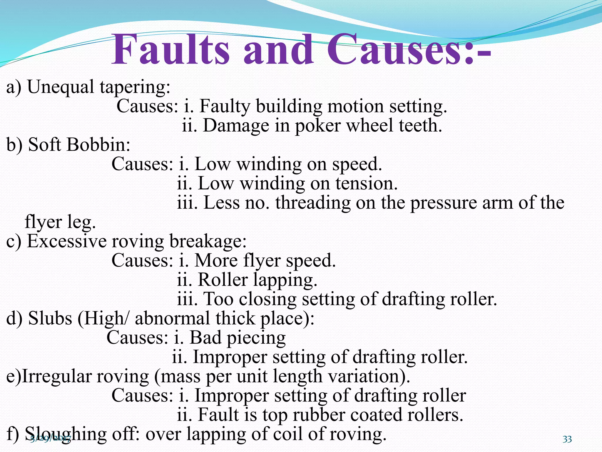
This document provides information about roving frames, including:
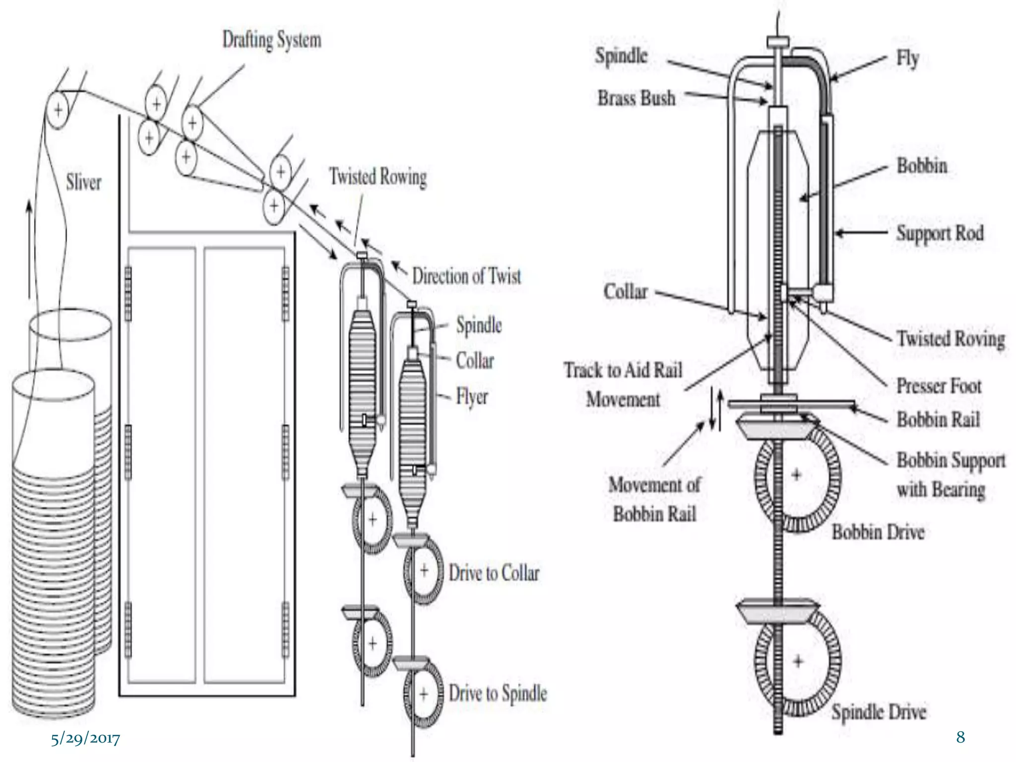
- Roving frames take sliver from draw frames and produce roved which is wound onto packages.
- They draft the sliver to a thin strand, impart twist for protection, and wind the roving onto packages.
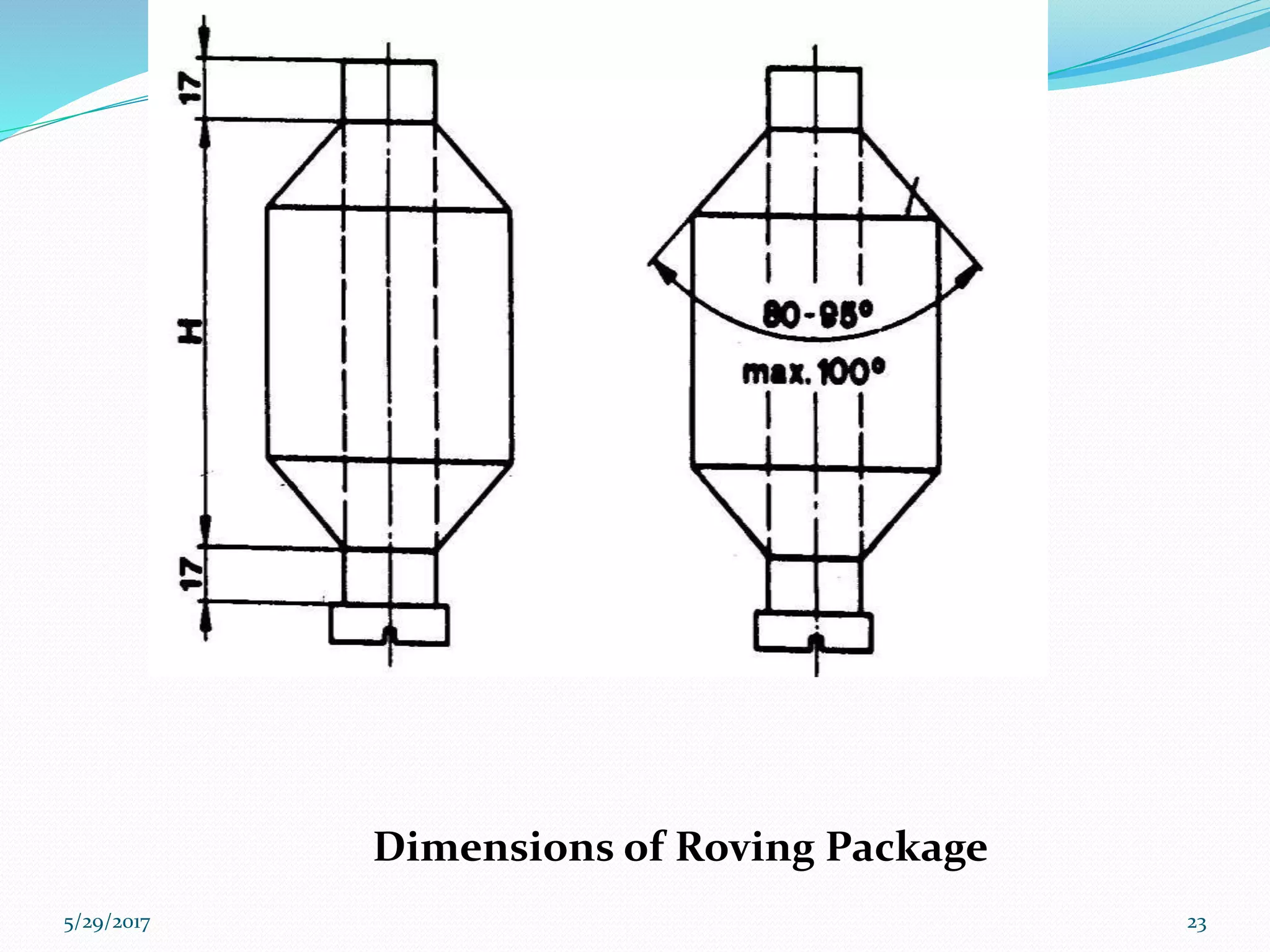
- The key components are the drafting system, flyer, and bobbin rail which winds the roving in layers onto packages.


![Yarn Manufacturing Process : Comber Part II [Modern combers]](https://cdn.slidesharecdn.com/ss_thumbnails/moderncombers-180912060904-thumbnail.jpg?width=640&height=640&fit=bounds)