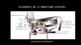
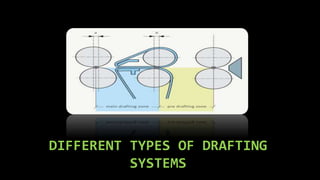
BRANCH: TEXTILE TECHNOLOGY
(sem: 4th )
SUBJECT: YARN
MANUFACTURING - II
GROUP NO:
1
PREPARED BY:
CHIRAG BANSAL (160420129003)
CHAUDHARY VIKESH (160420129002)
CHANDARANA SMIT (150420129002)
GUIDED BY:
PROF. SUDHIR YARDI
WHAT IS DRAFTING:
• Drafting is the creation of a drawing or other graphical representation of a
building, mechanical device or other structure for the purposes of determining
how the device should be created. Drafting is used as a part of the design and
fabrication processes. Drafting can be done by hand or using specially
designed computer programs and mechanical drawings.
• Drafting arrangement is the most important part of the machine. It
influencesmainly evenness and strength The following points are
therefore very important
ELEMENTS OF A DRAFTING SYSTEM:
3/3 Double Apron Drafting System
DIFFERENT TYPES OF DRAFTING
SYSTEMS
1) 3-OVER-3 DOUBLE APRON DRAFTING
SYSTEM:
• In production of a roving, a 3-over-3 roller with
double apron drafting system is commonly used
to attenuate the sliver.
• In a system of three pairs of rollers, there are
two drafting zones. The first or back zone is
designated the “break draft,” while the second
or front zone is called the “main draft”.
• A pair of endless aprons is positioned in the high-draft front zone and made to move at the
surface speed of the middle-roller pair.
• As fibers enter the high-draft front zone, the aprons will hold them and assist in keeping them
moving at the surface speed of the middle rollers, while preventing the short-fibers being
dragged forward by those fibers nipped and accelerated by the front rollers.
• The magnitude of break draft is usually small, varying between 1.1 and 1.5;
therefore the front draft (i.e. main draft) is responsible for the major part of the
total attenuation desired.
• The total draft is defined as the ratio of the surface speed of the front rolls to the
surface speed of the back rolls and is a product of the break draft and the main
draft:
2) 4-OVER-4 DOUBLE APRON DRAFTING
SYSTEM:
•In 4-over-4 double apron drafting system, there are
three drafting zones such as break draft, middle draft
and front draft (or main draft).
• Back draft is apply in back zone which affects roving
evenness. Less amount of draft is apply in middle zone
where the condenser is used to condense sheet like
sliver. Maximum amount of draft is apply in front zone
where the apron is used to move at the surface speed
of the middle-roller pair.
• The total draft is defined as the ratio of the surface
speed of the front rolls to the surface speed of the back
rolls and is a product of the break draft, middle draft
and the main draft:
3) RIETER DOUBLE APRON DRAFTING
SYSTEM WITH LONG BOTTOM APRON:
• In the double apron drafting system the fiber guidance unit
consists of two aprons rotating with the middle rollers. The
top apron must be pressed against the bottom apron with
controlled force in order to provide guidance. For this
purpose there must be a gap between the two aprons at the
apron delivery end (tensor gap) that is precisely adjusted to
the fiber volume. This gap can be adjusted by using different
spacer plates, shoes, etc.
• The top aprons, which are often plastic aprons, are always
short. However, the bottom aprons can be as short as the top
aprons or quite a bit longer and guided accordingly around
deflecting elements. The advantage of long bottom aprons
over short aprons is that they are easy to replace in the event
of damage. They are also less inclined to become clogged
with fiber fly.
4) CASABLANCA A500
• Casablanca A500 drafting represents the first development to improve the control
over floating fibers. Prior to that, a self-weighted light middle top roller was used
to control short fibers while allowing long fibers to slip underneath. Even now
some woollen ring frames employing this principle are found in operation in the
mills. In Casablanca drafting a pair of endless aprons driven by middle top
and bottom roller and held together by a tensor, is used to control the floating
fibers in the front zone. The back zone is merely a break draft zone with low
drafts. The back top roller is self weighted while middle and front top rollers are
weighted by a spring encased in a cage, through a saddle.
• Top arm drafting represents a major breakthrough in improving the quality and
performance of drafting. Most of the problems encountered with Casablanca
drafting are overcome in top arm drafting by adopting pendulum system of
central arbour guidance. Center suspension of top rollers ensures self-alignment of
top roller to a position axially parallel to bottom roller. Further, an apron guide bar
or nose bar is used to guide the bottom apron. The nose bar provides firm
guidance to the bottom apron and the strand over it and further brings down the
distance between apron release point and the front roller nip. As a result, the fiber
control is improved
5) OM – SUPER HIGH DRAFT SYSTEM:
• This system is specially designed to spin direct from
drawing sliver using special size small sliver cans in place
of usual roving bobbin in the creels as shown in the figure
below fig. –
• The back draft zone is in vertical position and the front
zone is inclined position to 500. The rollers are spring
weighted. In this system the back draft zone is equivalent
to the draft of a sliver and the drafting arrangement
resembles to that of the long draft sliver (Back, 4th and
3rd rollers). The front zone (3rd, 2nd, and front roller)
resembles the ordinary Casablanca's system.
• It is claimed that, draft from 300 – 400 for count of 60s –
80s and 150 – 250 for count 20s – 40s can be obtained.
6) PNEUMATIC LOADING SYSTEM (RIETER
FS 160 P3.1):
• The loading support is stamped from steel sheet and is
mounted on a continuous hexagonal section tube behindthe
rollers. The tube contains the compressed air hose connected to
a central compressor unit. Three top roller holders mounted on
two bearing slides are accommodated in the loading support
itself. The two bearing slides form a double lever system.
Depending on where a pin is inserted in one of the three holes
as the pivot at m“, the total pressure coming from the
compressed air hose and acting on the entire pressure arm via a
cam is applied more strongly to the back roller or the two front
rollers. Pressure can also be distributed differently between the
twofront rollers via a second pin/hole system in the bearing slide
of these two rollers at n“.
Pneumatic loading by Rieter
7) SPRING LOADED PRESSURE ARM SYSTEM
(TEXPARTS PK225):
SKF PK 225 rocking support
Each compensating roller is seated in a
bearing slide (1, 2, 3); these are infinitely
adjustable relative to each other. A
spring (4,5, 6) – sometimes two on the
front
roller – presses the top roller against the
bottom roller. In the case of SKF the loading
pressure can simply be adjusted in three
stages by means of a tool. Colored marks
indicated the set loading stage.
BIBLIOGRAPHY / REFERENCES
• http://www.rieter.com/en/rikipedia/articles/ring-spinning/structural-
configuration-of-the-machine/the-drafting-system/fiber-guidance-devices/double-
apron-drafting-system-with-long-bottomapron/
• https://textilestudycenter.com/drafting-system-of-roving-frame/
• https://www.academia.edu/3773342/Developments_in_drafting
• http://www.rieter.com/en/rikipedia/articles/processing-of-man-made-
fibres/processing-of-man-made-staple-fibres-in-spinning-mill/drawing/general-
settings/roller-setting/
• https://textileapex.blogspot.in/2014/11/drafting-system-in-ring-frame.html
THANK
YOU

DIFFERENT TYPES OF DRAFTING SYSTEMS

  • 1.
    BRANCH: TEXTILE TECHNOLOGY (sem:4th ) SUBJECT: YARN MANUFACTURING - II GROUP NO: 1
  • 2.
    PREPARED BY: CHIRAG BANSAL(160420129003) CHAUDHARY VIKESH (160420129002) CHANDARANA SMIT (150420129002) GUIDED BY: PROF. SUDHIR YARDI
  • 3.
    WHAT IS DRAFTING: •Drafting is the creation of a drawing or other graphical representation of a building, mechanical device or other structure for the purposes of determining how the device should be created. Drafting is used as a part of the design and fabrication processes. Drafting can be done by hand or using specially designed computer programs and mechanical drawings. • Drafting arrangement is the most important part of the machine. It influencesmainly evenness and strength The following points are therefore very important
  • 4.
    ELEMENTS OF ADRAFTING SYSTEM: 3/3 Double Apron Drafting System
  • 5.
    DIFFERENT TYPES OFDRAFTING SYSTEMS
  • 6.
    1) 3-OVER-3 DOUBLEAPRON DRAFTING SYSTEM: • In production of a roving, a 3-over-3 roller with double apron drafting system is commonly used to attenuate the sliver. • In a system of three pairs of rollers, there are two drafting zones. The first or back zone is designated the “break draft,” while the second or front zone is called the “main draft”. • A pair of endless aprons is positioned in the high-draft front zone and made to move at the surface speed of the middle-roller pair. • As fibers enter the high-draft front zone, the aprons will hold them and assist in keeping them moving at the surface speed of the middle rollers, while preventing the short-fibers being dragged forward by those fibers nipped and accelerated by the front rollers.
  • 7.
    • The magnitudeof break draft is usually small, varying between 1.1 and 1.5; therefore the front draft (i.e. main draft) is responsible for the major part of the total attenuation desired. • The total draft is defined as the ratio of the surface speed of the front rolls to the surface speed of the back rolls and is a product of the break draft and the main draft:
  • 8.
    2) 4-OVER-4 DOUBLEAPRON DRAFTING SYSTEM: •In 4-over-4 double apron drafting system, there are three drafting zones such as break draft, middle draft and front draft (or main draft). • Back draft is apply in back zone which affects roving evenness. Less amount of draft is apply in middle zone where the condenser is used to condense sheet like sliver. Maximum amount of draft is apply in front zone where the apron is used to move at the surface speed of the middle-roller pair. • The total draft is defined as the ratio of the surface speed of the front rolls to the surface speed of the back rolls and is a product of the break draft, middle draft and the main draft:
  • 9.
    3) RIETER DOUBLEAPRON DRAFTING SYSTEM WITH LONG BOTTOM APRON: • In the double apron drafting system the fiber guidance unit consists of two aprons rotating with the middle rollers. The top apron must be pressed against the bottom apron with controlled force in order to provide guidance. For this purpose there must be a gap between the two aprons at the apron delivery end (tensor gap) that is precisely adjusted to the fiber volume. This gap can be adjusted by using different spacer plates, shoes, etc. • The top aprons, which are often plastic aprons, are always short. However, the bottom aprons can be as short as the top aprons or quite a bit longer and guided accordingly around deflecting elements. The advantage of long bottom aprons over short aprons is that they are easy to replace in the event of damage. They are also less inclined to become clogged with fiber fly.
  • 10.
    4) CASABLANCA A500 •Casablanca A500 drafting represents the first development to improve the control over floating fibers. Prior to that, a self-weighted light middle top roller was used to control short fibers while allowing long fibers to slip underneath. Even now some woollen ring frames employing this principle are found in operation in the mills. In Casablanca drafting a pair of endless aprons driven by middle top and bottom roller and held together by a tensor, is used to control the floating fibers in the front zone. The back zone is merely a break draft zone with low drafts. The back top roller is self weighted while middle and front top rollers are weighted by a spring encased in a cage, through a saddle. • Top arm drafting represents a major breakthrough in improving the quality and performance of drafting. Most of the problems encountered with Casablanca drafting are overcome in top arm drafting by adopting pendulum system of central arbour guidance. Center suspension of top rollers ensures self-alignment of top roller to a position axially parallel to bottom roller. Further, an apron guide bar or nose bar is used to guide the bottom apron. The nose bar provides firm guidance to the bottom apron and the strand over it and further brings down the distance between apron release point and the front roller nip. As a result, the fiber control is improved
  • 11.
    5) OM –SUPER HIGH DRAFT SYSTEM: • This system is specially designed to spin direct from drawing sliver using special size small sliver cans in place of usual roving bobbin in the creels as shown in the figure below fig. – • The back draft zone is in vertical position and the front zone is inclined position to 500. The rollers are spring weighted. In this system the back draft zone is equivalent to the draft of a sliver and the drafting arrangement resembles to that of the long draft sliver (Back, 4th and 3rd rollers). The front zone (3rd, 2nd, and front roller) resembles the ordinary Casablanca's system. • It is claimed that, draft from 300 – 400 for count of 60s – 80s and 150 – 250 for count 20s – 40s can be obtained.
  • 12.
    6) PNEUMATIC LOADINGSYSTEM (RIETER FS 160 P3.1): • The loading support is stamped from steel sheet and is mounted on a continuous hexagonal section tube behindthe rollers. The tube contains the compressed air hose connected to a central compressor unit. Three top roller holders mounted on two bearing slides are accommodated in the loading support itself. The two bearing slides form a double lever system. Depending on where a pin is inserted in one of the three holes as the pivot at m“, the total pressure coming from the compressed air hose and acting on the entire pressure arm via a cam is applied more strongly to the back roller or the two front rollers. Pressure can also be distributed differently between the twofront rollers via a second pin/hole system in the bearing slide of these two rollers at n“. Pneumatic loading by Rieter
  • 13.
    7) SPRING LOADEDPRESSURE ARM SYSTEM (TEXPARTS PK225): SKF PK 225 rocking support Each compensating roller is seated in a bearing slide (1, 2, 3); these are infinitely adjustable relative to each other. A spring (4,5, 6) – sometimes two on the front roller – presses the top roller against the bottom roller. In the case of SKF the loading pressure can simply be adjusted in three stages by means of a tool. Colored marks indicated the set loading stage.
  • 14.
    BIBLIOGRAPHY / REFERENCES •http://www.rieter.com/en/rikipedia/articles/ring-spinning/structural- configuration-of-the-machine/the-drafting-system/fiber-guidance-devices/double- apron-drafting-system-with-long-bottomapron/ • https://textilestudycenter.com/drafting-system-of-roving-frame/ • https://www.academia.edu/3773342/Developments_in_drafting • http://www.rieter.com/en/rikipedia/articles/processing-of-man-made- fibres/processing-of-man-made-staple-fibres-in-spinning-mill/drawing/general- settings/roller-setting/ • https://textileapex.blogspot.in/2014/11/drafting-system-in-ring-frame.html
  • 15.