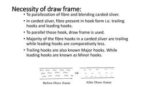
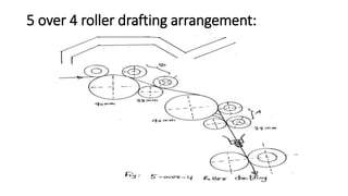
SlideShare a Scribd company logo
Draw frame
Yarn Manufacturing-I
Draw frame
• It is a process of yarn
manufacturing in which
the sliver is elongated
when passing through
pairs of rollers, each pair
faster than the previous
one.
• This permits combination
of several slivers and
drawing and elongating
them to straighten and to
create greater uniformity.
Objects of drawing
•To straighten the fibres in the
slivers.
•To make them lie is a manner
parallel to their neighbours and
to the sliver axis.
•To improve the uniformity and
evenness of the slivers.
•To reduce weight per unit
length of sliver.
•To reduce irregularities of fibre
by doubling and drafting.
•To remove dust from sliver.
•To make perfect blending of the
sliver.
Necessity of draw frame:
• To parallezation of fibre and blending carded sliver.
• In carded sliver, fibre present in hook form i.e. trailing
hooks and leading hooks.
• To parallel those hook, draw frame is used.
• Majority of the fibre hooks in a carded sliver are trailing
while leading hooks are comparatively less.
• Trailing hooks are also known Major hooks. While
leading hooks are known as Minor hooks.
Tasks of draw frame
• Equalizing.
• Parallelizing.
• Blending.
• Dust removal.
Actions involved in Draw frame
• Drafting: The process of attenuating or increasing length per unit
weight of sliver. It is mainly due to peripheral speed of the rollers.
• Doubling : The process of combining two or more carded sliver into a
single form is called doubling. In draw frame m/c generally six slivers
are fed and converted into one i.e. six doubling.
• Drawing : In the cotton Industry, the term is applied exclusively to
processing on the draw frame, where the operation is one of doubling
and drafting.
• Operating device:
• Creel (Sliver feed)
• The drafting
arrangement.
• Suction systems for the
drafting arrangement.
• Coiling.
• Can changers.
 Creel:
 The creel must be
designed so that:
 False drafts are
avoided.
 The m/c stops upon
occurrence of sliver
break.
 Sliver breaks can be
dealt with easily,
comfortably and
safely.
Requirements of drafting arrangements
• Simple, uncomplicated construction.
• Stable design with smooth running of the rollers.
• A mode of operation giving a high quality product even
at high running speeds.
• High degree of flexibility i.e. suitability for all raw mtls.
• Optimal control over the movement of the fibres during
the drafting operation.
• High precision both of operation and adjustment.
• Rapid and simple adjustability of roller spacing and draft
levels.
• Ease of maintenance and cleanings.
• Optimal ergonomic design.
Influence on the draft: Factors depending upon
fiber material
• Mass of the fibre in the strand cross-section.
• Degree of order of the fibre.
• Shape of cross section of the fibre strand.
• Compactness of the fibre strand.
• Adhesion betn the fibres depend upon-
• Surface structure.
• Crimp.
• Lubrication.
• Compression of the strand.
• Fibre length.
• Evenness of distribution of fibre lengths.
• Twist in the fibre strand.
Influence on the draft: Factors depending upon the drafting
arrangements
• Diameter of the rollers.
• Hardness of top rollers.
• Pressure exerted by the top rollers.
• Surface characteristics of the top rollers.
• Fluting the bottom rollers.
• Type and form of fibre guiding devices, such as pressure rods, pin bars,
aprons, condenser etc.
• Clamping distances(Roller setting)
• Level of the draft.
• Distribution of draft betn the various drafting stages.
Elements of drafting arrangements in short staple
spinning generally:
• 1.Bottom rollers: Positively driven, made of
metal.
• Axial flutes.
• Spiral flutes.
• Knurled flutes.
• 2. Top rollers: Not Positively Driven, one piece
rollers or twin rollers, Soft coats
• 3. Top roller pressure: Pressure can be
generated by loading by means of-
• Dead weights.
• Spring weighting.
• Hydraulic system.
• Pneumatic weighting.
• Magnetic weighting.
Forms of drafting arrangement used on draw
frame:
• 3 over 4 roller drafting arrangement
3 over 4 roller drafting arrangement
Advantages: Disadvantages:
• The widely change of setting
range is possible.
• Control of fibre is increased due
to drafting over surface.
• Suitable for processing of long
fibre.
• Not suitable for processing of
short fibre.
• Not make so much close of nip
setting of back and front zone as
4 over 4 system.
• No drafting in the middle zone.
3 over 3 drafting arrangement:
4 over 3 roller drafting arrangement
Farhana Momotaz, Lecturer, Dept of TE, KUET
5 over 4 roller drafting arrangement:
Farhana Momotaz, Lecturer, Dept of TE, KUET
Features of modern Draw Frame: (Recent
developments)
• High speed of production.
• High draft.
• Better control of short fibre.
• Autolevelling.
• Auto stop motion system.
• Electronic control and display unit.
• Auto drafting system.
• Improved drafting system.
• Can linking system.
• Rectangular can.
• Automatic can changer.
• Suction system for the drafting arrangement.
Fault locating indication lamp
Red Stop without problem
Green Sliver breaks, Roller lapping
Yellow After fill up of sliver can, no empty can



Machine monitor
Monitoring system Production monitor.
Quality monitor.







FEATURES OF MODERN DRAW FRAME: (RECENT
DEVELOPMENTS)
Effect of Draft, Doubling on sliver quality:
Doubling
Drafting
C.V%
C.V%

More Related Content

Similar to Draw frame.pptx

Jute spinning assingnment_MD. SALIM RANA_DUET
Jute spinning assingnment_MD. SALIM RANA_DUETJute spinning assingnment_MD. SALIM RANA_DUET
Jute spinning assingnment_MD. SALIM RANA_DUET
SaLim Rana
 
conveyor belt Presentation.pdf
conveyor belt Presentation.pdfconveyor belt Presentation.pdf
conveyor belt Presentation.pdf
Pownu
 

Similar to Draw frame.pptx (20)

WARPING PRESENTATION
WARPING PRESENTATION WARPING PRESENTATION
WARPING PRESENTATION
 
Sizing PPT.pptx
Sizing PPT.pptxSizing PPT.pptx
Sizing PPT.pptx
 
BRAIDING.ppt
BRAIDING.pptBRAIDING.ppt
BRAIDING.ppt
 
comprehension 1 knitting
 comprehension 1 knitting comprehension 1 knitting
comprehension 1 knitting
 
Chapter 4
Chapter 4Chapter 4
Chapter 4
 
Woven Fabric Design: Selvedge
Woven Fabric Design: SelvedgeWoven Fabric Design: Selvedge
Woven Fabric Design: Selvedge
 
Woven Fabric Design: Selvedge
Woven Fabric Design: SelvedgeWoven Fabric Design: Selvedge
Woven Fabric Design: Selvedge
 
Design of Transmission Systems
Design of Transmission SystemsDesign of Transmission Systems
Design of Transmission Systems
 
Roving
RovingRoving
Roving
 
Lecture_18-19_Flat Belt Drive.pptx
Lecture_18-19_Flat Belt Drive.pptxLecture_18-19_Flat Belt Drive.pptx
Lecture_18-19_Flat Belt Drive.pptx
 
Different drawing methods pankaj kumar das
Different drawing methods pankaj kumar dasDifferent drawing methods pankaj kumar das
Different drawing methods pankaj kumar das
 
Warping
WarpingWarping
Warping
 
Spinning [compatibility mode],Yarn types classification
Spinning [compatibility mode],Yarn types classificationSpinning [compatibility mode],Yarn types classification
Spinning [compatibility mode],Yarn types classification
 
Modern ring frame_ppt_in_spg
Modern ring frame_ppt_in_spgModern ring frame_ppt_in_spg
Modern ring frame_ppt_in_spg
 
Jute spinning assingnment_MD. SALIM RANA_DUET
Jute spinning assingnment_MD. SALIM RANA_DUETJute spinning assingnment_MD. SALIM RANA_DUET
Jute spinning assingnment_MD. SALIM RANA_DUET
 
filamentwinding-\
filamentwinding-\filamentwinding-\
filamentwinding-\
 
Filament winding نآمیرا فارسیمادان
Filament winding  نآمیرا فارسیمادانFilament winding  نآمیرا فارسیمادان
Filament winding نآمیرا فارسیمادان
 
Draw frame
Draw frameDraw frame
Draw frame
 
Warping phpapp3648
Warping phpapp3648Warping phpapp3648
Warping phpapp3648
 
conveyor belt Presentation.pdf
conveyor belt Presentation.pdfconveyor belt Presentation.pdf
conveyor belt Presentation.pdf
 

Recently uploaded

Automobile Management System Project Report.pdf
Automobile Management System Project Report.pdfAutomobile Management System Project Report.pdf
Automobile Management System Project Report.pdf
Kamal Acharya
 
Standard Reomte Control Interface - Neometrix
Standard Reomte Control Interface - NeometrixStandard Reomte Control Interface - Neometrix
Standard Reomte Control Interface - Neometrix
Neometrix_Engineering_Pvt_Ltd
 
CFD Simulation of By-pass Flow in a HRSG module by R&R Consult.pptx
CFD Simulation of By-pass Flow in a HRSG module by R&R Consult.pptxCFD Simulation of By-pass Flow in a HRSG module by R&R Consult.pptx
CFD Simulation of By-pass Flow in a HRSG module by R&R Consult.pptx
R&R Consult
 
ONLINE VEHICLE RENTAL SYSTEM PROJECT REPORT.pdf
ONLINE VEHICLE RENTAL SYSTEM PROJECT REPORT.pdfONLINE VEHICLE RENTAL SYSTEM PROJECT REPORT.pdf
ONLINE VEHICLE RENTAL SYSTEM PROJECT REPORT.pdf
Kamal Acharya
 

Recently uploaded (20)

Automobile Management System Project Report.pdf
Automobile Management System Project Report.pdfAutomobile Management System Project Report.pdf
Automobile Management System Project Report.pdf
 
Standard Reomte Control Interface - Neometrix
Standard Reomte Control Interface - NeometrixStandard Reomte Control Interface - Neometrix
Standard Reomte Control Interface - Neometrix
 
NO1 Pandit Amil Baba In Bahawalpur, Sargodha, Sialkot, Sheikhupura, Rahim Yar...
NO1 Pandit Amil Baba In Bahawalpur, Sargodha, Sialkot, Sheikhupura, Rahim Yar...NO1 Pandit Amil Baba In Bahawalpur, Sargodha, Sialkot, Sheikhupura, Rahim Yar...
NO1 Pandit Amil Baba In Bahawalpur, Sargodha, Sialkot, Sheikhupura, Rahim Yar...
 
Peek implant persentation - Copy (1).pdf
Peek implant persentation - Copy (1).pdfPeek implant persentation - Copy (1).pdf
Peek implant persentation - Copy (1).pdf
 
KIT-601 Lecture Notes-UNIT-3.pdf Mining Data Stream
KIT-601 Lecture Notes-UNIT-3.pdf Mining Data StreamKIT-601 Lecture Notes-UNIT-3.pdf Mining Data Stream
KIT-601 Lecture Notes-UNIT-3.pdf Mining Data Stream
 
Top 13 Famous Civil Engineering Scientist
Top 13 Famous Civil Engineering ScientistTop 13 Famous Civil Engineering Scientist
Top 13 Famous Civil Engineering Scientist
 
shape functions of 1D and 2 D rectangular elements.pptx
shape functions of 1D and 2 D rectangular elements.pptxshape functions of 1D and 2 D rectangular elements.pptx
shape functions of 1D and 2 D rectangular elements.pptx
 
Furniture showroom management system project.pdf
Furniture showroom management system project.pdfFurniture showroom management system project.pdf
Furniture showroom management system project.pdf
 
Cloud-Computing_CSE311_Computer-Networking CSE GUB BD - Shahidul.pptx
Cloud-Computing_CSE311_Computer-Networking CSE GUB BD - Shahidul.pptxCloud-Computing_CSE311_Computer-Networking CSE GUB BD - Shahidul.pptx
Cloud-Computing_CSE311_Computer-Networking CSE GUB BD - Shahidul.pptx
 
A case study of cinema management system project report..pdf
A case study of cinema management system project report..pdfA case study of cinema management system project report..pdf
A case study of cinema management system project report..pdf
 
The Benefits and Techniques of Trenchless Pipe Repair.pdf
The Benefits and Techniques of Trenchless Pipe Repair.pdfThe Benefits and Techniques of Trenchless Pipe Repair.pdf
The Benefits and Techniques of Trenchless Pipe Repair.pdf
 
CFD Simulation of By-pass Flow in a HRSG module by R&R Consult.pptx
CFD Simulation of By-pass Flow in a HRSG module by R&R Consult.pptxCFD Simulation of By-pass Flow in a HRSG module by R&R Consult.pptx
CFD Simulation of By-pass Flow in a HRSG module by R&R Consult.pptx
 
ONLINE VEHICLE RENTAL SYSTEM PROJECT REPORT.pdf
ONLINE VEHICLE RENTAL SYSTEM PROJECT REPORT.pdfONLINE VEHICLE RENTAL SYSTEM PROJECT REPORT.pdf
ONLINE VEHICLE RENTAL SYSTEM PROJECT REPORT.pdf
 
Explosives Industry manufacturing process.pdf
Explosives Industry manufacturing process.pdfExplosives Industry manufacturing process.pdf
Explosives Industry manufacturing process.pdf
 
Introduction to Machine Learning Unit-4 Notes for II-II Mechanical Engineering
Introduction to Machine Learning Unit-4 Notes for II-II Mechanical EngineeringIntroduction to Machine Learning Unit-4 Notes for II-II Mechanical Engineering
Introduction to Machine Learning Unit-4 Notes for II-II Mechanical Engineering
 
Arduino based vehicle speed tracker project
Arduino based vehicle speed tracker projectArduino based vehicle speed tracker project
Arduino based vehicle speed tracker project
 
KIT-601 Lecture Notes-UNIT-4.pdf Frequent Itemsets and Clustering
KIT-601 Lecture Notes-UNIT-4.pdf Frequent Itemsets and ClusteringKIT-601 Lecture Notes-UNIT-4.pdf Frequent Itemsets and Clustering
KIT-601 Lecture Notes-UNIT-4.pdf Frequent Itemsets and Clustering
 
NO1 Pandit Black Magic Removal in Uk kala jadu Specialist kala jadu for Love ...
NO1 Pandit Black Magic Removal in Uk kala jadu Specialist kala jadu for Love ...NO1 Pandit Black Magic Removal in Uk kala jadu Specialist kala jadu for Love ...
NO1 Pandit Black Magic Removal in Uk kala jadu Specialist kala jadu for Love ...
 
AI for workflow automation Use cases applications benefits and development.pdf
AI for workflow automation Use cases applications benefits and development.pdfAI for workflow automation Use cases applications benefits and development.pdf
AI for workflow automation Use cases applications benefits and development.pdf
 
ENERGY STORAGE DEVICES INTRODUCTION UNIT-I
ENERGY STORAGE DEVICES  INTRODUCTION UNIT-IENERGY STORAGE DEVICES  INTRODUCTION UNIT-I
ENERGY STORAGE DEVICES INTRODUCTION UNIT-I
 

Draw frame.pptx

  • 2. Draw frame • It is a process of yarn manufacturing in which the sliver is elongated when passing through pairs of rollers, each pair faster than the previous one. • This permits combination of several slivers and drawing and elongating them to straighten and to create greater uniformity. Objects of drawing •To straighten the fibres in the slivers. •To make them lie is a manner parallel to their neighbours and to the sliver axis. •To improve the uniformity and evenness of the slivers. •To reduce weight per unit length of sliver. •To reduce irregularities of fibre by doubling and drafting. •To remove dust from sliver. •To make perfect blending of the sliver.
  • 3. Necessity of draw frame: • To parallezation of fibre and blending carded sliver. • In carded sliver, fibre present in hook form i.e. trailing hooks and leading hooks. • To parallel those hook, draw frame is used. • Majority of the fibre hooks in a carded sliver are trailing while leading hooks are comparatively less. • Trailing hooks are also known Major hooks. While leading hooks are known as Minor hooks.
  • 4. Tasks of draw frame • Equalizing. • Parallelizing. • Blending. • Dust removal.
  • 5. Actions involved in Draw frame • Drafting: The process of attenuating or increasing length per unit weight of sliver. It is mainly due to peripheral speed of the rollers. • Doubling : The process of combining two or more carded sliver into a single form is called doubling. In draw frame m/c generally six slivers are fed and converted into one i.e. six doubling. • Drawing : In the cotton Industry, the term is applied exclusively to processing on the draw frame, where the operation is one of doubling and drafting.
  • 6. • Operating device: • Creel (Sliver feed) • The drafting arrangement. • Suction systems for the drafting arrangement. • Coiling. • Can changers.  Creel:  The creel must be designed so that:  False drafts are avoided.  The m/c stops upon occurrence of sliver break.  Sliver breaks can be dealt with easily, comfortably and safely.
  • 7. Requirements of drafting arrangements • Simple, uncomplicated construction. • Stable design with smooth running of the rollers. • A mode of operation giving a high quality product even at high running speeds. • High degree of flexibility i.e. suitability for all raw mtls. • Optimal control over the movement of the fibres during the drafting operation. • High precision both of operation and adjustment. • Rapid and simple adjustability of roller spacing and draft levels. • Ease of maintenance and cleanings. • Optimal ergonomic design.
  • 8. Influence on the draft: Factors depending upon fiber material • Mass of the fibre in the strand cross-section. • Degree of order of the fibre. • Shape of cross section of the fibre strand. • Compactness of the fibre strand. • Adhesion betn the fibres depend upon- • Surface structure. • Crimp. • Lubrication. • Compression of the strand. • Fibre length. • Evenness of distribution of fibre lengths. • Twist in the fibre strand.
  • 9. Influence on the draft: Factors depending upon the drafting arrangements • Diameter of the rollers. • Hardness of top rollers. • Pressure exerted by the top rollers. • Surface characteristics of the top rollers. • Fluting the bottom rollers. • Type and form of fibre guiding devices, such as pressure rods, pin bars, aprons, condenser etc. • Clamping distances(Roller setting) • Level of the draft. • Distribution of draft betn the various drafting stages.
  • 10. Elements of drafting arrangements in short staple spinning generally: • 1.Bottom rollers: Positively driven, made of metal. • Axial flutes. • Spiral flutes. • Knurled flutes. • 2. Top rollers: Not Positively Driven, one piece rollers or twin rollers, Soft coats • 3. Top roller pressure: Pressure can be generated by loading by means of- • Dead weights. • Spring weighting. • Hydraulic system. • Pneumatic weighting. • Magnetic weighting.
  • 11. Forms of drafting arrangement used on draw frame: • 3 over 4 roller drafting arrangement
  • 12. 3 over 4 roller drafting arrangement Advantages: Disadvantages: • The widely change of setting range is possible. • Control of fibre is increased due to drafting over surface. • Suitable for processing of long fibre. • Not suitable for processing of short fibre. • Not make so much close of nip setting of back and front zone as 4 over 4 system. • No drafting in the middle zone.
  • 13. 3 over 3 drafting arrangement:
  • 14. 4 over 3 roller drafting arrangement Farhana Momotaz, Lecturer, Dept of TE, KUET
  • 15. 5 over 4 roller drafting arrangement: Farhana Momotaz, Lecturer, Dept of TE, KUET
  • 16. Features of modern Draw Frame: (Recent developments) • High speed of production. • High draft. • Better control of short fibre. • Autolevelling. • Auto stop motion system. • Electronic control and display unit. • Auto drafting system. • Improved drafting system. • Can linking system. • Rectangular can. • Automatic can changer. • Suction system for the drafting arrangement.
  • 17. Fault locating indication lamp Red Stop without problem Green Sliver breaks, Roller lapping Yellow After fill up of sliver can, no empty can    Machine monitor Monitoring system Production monitor. Quality monitor.        FEATURES OF MODERN DRAW FRAME: (RECENT DEVELOPMENTS)
  • 18. Effect of Draft, Doubling on sliver quality: Doubling Drafting C.V% C.V%