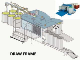
Draw frame
•
69 likes•34,077 views

This document discusses the objectives, operating principles, and components of a draw frame used in yarn production. The main objectives of a draw frame are equalizing fiber distribution, parallelizing fibers, blending fibers, and removing dust. It operates by drafting multiple sliver feeds together using roller pairs with differential speeds. Key components discussed include the creel, drafting arrangement, dust removal, coiling, and monitoring/auto-leveling systems.

Recommended
More Related Content
What's hot
What's hot (20)
Similar to Draw frame
Similar to Draw frame (20)
More from Farhan ullah baig
More from Farhan ullah baig (20)
Recently uploaded
Recently uploaded (20)
Draw frame
- 2. Introduction 1. Production costs of draw frame is less than 3% of total yarn cost. 2. But it has great influence on yarn quality specially on evenness. 3. Draw frame is the definitive compensation point for eliminating errors. 4. High-performance draw frames currently produce over 400 kg of sliver per hour at each delivery.
- 4. Objectives of Draw Frame Equalizing One of the main tasks of the draw frame is improving evenness over the short, medium and – especially – long term. Parallelizing To obtain an optimal value for strength in the yarn characteristics, the fibers must be arranged parallel in the fiber strand. It is mainly the draw frame‘s task to create this parallel arrangement. It fulfills this task by means of the draft, since every drafting step leads to straightening of the fibers. Blending In addition to the equalizing effect, doubling also provides a degree of compensation of raw material variations by blending, which occurs simultaneously. Dust removal Dust is steadily becoming a greater problem both in processing and for the personnel involved. It is therefore important to remove dust to the greatest practical extent at every possible point within the overall process.
- 5. Operating principle Four to eight card or draw frame slivers are fed to the drafting arrangement (3). A feed roller pair (2) is located above each can (1) to enable the feeding step to be performed in a controlled manner without false drafts. The feed roller pairs are mounted in a creel frame or table and each is positively driven. The slivers running into the drafting arrangement leave it, after a draft of 4 to 8, as a web lacking significant cohesion. In order to avoid disintegration of the web, which would otherwise be unavoidable at the high operating speeds currently in use, it is condensed into a sliver immediately after the drafting arrangement. This sliver is then guided through a tube (4) via a passage (6) of the tube gear into a can (7), in which it must be laid in clean coils with optimal utilization of the space in the can. To enable the can to take up as much material as possible, the sliver is compressed by passing it through calendaring rollers (5).
- 6. Sectional view of a draw frame
- 7. Creel (sliver feed) Creel objectives 1. false drafts are avoided; 2. the machine stops immediately when a sliver break occurs; 3. sliver breaks can be dealt with easily, comfortably and safely. Creel types 1. Static or stationary creel 2. Power creel
- 8. Different systems of power creels
- 14. Requirements of the Drafting Arrangement The drafting arrangement is the heart of the draw frame and thus the part which exerts the most decisive influence on quality. The requirements placed on the drafting arrangement in general are correspondingly high: Simple, uncomplicated construction; Stable design with smooth running of the rollers (centricity); A mode of operation producing a high-quality product even at high running speeds;
- 15. High degree of flexibility, i.e. Suitability for all raw materials, fiber lengths, sliver hanks, etc., That might be processed in the short staple spinning mill; Optimal control over the movement of the fibers during the drafting operation; High precision of both operation and adjustment; Rapid and simple adjustability of roller spacing and draft levels; Ease of maintenance and cleaning; Optimal ergonomic design.
- 16. Influences on the Draft Factors based upon the Fiber Material: Mass of fiber in the strand cross section; Degree of order of the fibers (parallel disposition); Shape of the cross section of the fiber strand; Compactness of the fiber strand; Adhesion between the fibers dependent upon I. Surface structure, II. Crimp, III. Spin finish, Compression of the strand; Fiber length; Evenness of distribution of fiber lengths (staple form); Existing twist in the fiber strand.
- 17. Factors based upon the Drafting Arrangement: Diameter of the rollers; Hardness of the top rollers; Pressure exerted by the top rollers; Surface characteristics of the top rollers; Fluting of the bottom rollers; Type and form of fiber guiding devices, such as pressure rods, pin bars, aprons, condenser etc.; Clamping distances (roller settings); Level of draft; Distribution of draft between the various drafting zones.
- 18. Elements of Drafting arrangement
- 22. Draft zone distance or roller setting At the draw frames, the drafting of the slivers takes place through pairs of rollers set apart at a pre-defined distance and rotating at different speeds. The distance between the nips of the pairs of rollers is commonly referred as the ‘roller setting’. The roller setting should neither be too close nor wide. If the setting is closer than the length of the fibers, due to the differential speed of the rollers, these fibers tend to break resulting in poor quality of the delivered sliver. If the setting is wide, during the drafting process, the shorter fibers tend to move without control once they cross the back roller, which again would result in inferior quality of the delivered sliver.
- 23. It is therefore obvious that a compromise between the two effects has to be reached by arriving at an optimum roller setting . So that the yarn quality obtained could be optimum. The fibre distribution plays an important role in deciding this optimum setting. Over the years, several recommendations have been provided to arrive at the optimum setting from the fibre length distribution. It is generally agreed that the optimum roller setting is just higher than the long fibers in the drafting zone. Available recommendations are based on the 2.5% span length from fibrograph and the 5% length from staple diagram of currently available methods.
- 24. Draft Distribution Three-line drafting arrangements, with two draft zones, are generally used in the short staple spinning mill In Asia still four- or five-line drafting arrangements are in use. The task of the draft in the first draft zone (break draft) is simply to prepare the main draft in the second zone. The fibers must be straightened and extended to such a degree that the main draft can immediately cause fiber movements, without still being strongly burdened with preparatory work. In this way, the main draft can be effected with less disturbance. The extent of break draft normally lies below the critical draft region.
- 25. In some cases, a higher break draft is needed. The main draft must be adapted to the drafting conditions, mainly the fiber mass in the drafting zone and the arrangement of the fibers in the strand. The draft can be increased with increasing fineness of the intermediate product, and also with increasing parallelization of the fibers. Since the fibers in card sliver are relatively randomly oriented, the draft in the first drawframe passage should not be too high. Unless there are conflicting reasons, the draft can then be increased at the second passage and so on continually to the ring spinning machine.
- 26. Additional Effects of Draft In addition to the reduction in diameter, draft causes: • stretching out of the fibers; • straightening of the fibers; • parallelizing of the fibers. All of these represent important operations for spinning.
- 27. Recommended values for the Main Draft Distance HVD Determine the fiber length with the staple diagram. Select the appropriate main draft distance HVD from the table.
- 28. Recommended values for Break Draft Distance VVD The break draft distance VVD is dependent of the fiber parallelism (number of drafting passages), the drafting resistance and the value of the break draft. High drafts VV (break draft) -> narrow break draft distance VVD; Low draft VV (break draft) ==> wide break draft distance VVD. The drafting passage of the draw frame must be considered. Select the appropriate break draft distance VVD for the matching drafting passage, from the table.
- 43. Dust Removal
- 49. Coiling The Delivery Arrangement To avoid disintegration of the web, it must be collected together in a converging tube immediately after the delivery roller and guided to the sliver trumpet. The design of the trumpet is very important, as it is responsible for the proper integration of the edge fibers of the fiber strand. The bore of this sliver trumpet must be adapted precisely to the sliver volume (sliver hank). These technological parts are therefore interchangeable.
- 50. Condensing Downstream from the trumpet, the sliver runs between two calendar rollers which are pressed towards each other. This condensing of the sliver enables more material to be fitted into the cans. Several manufacturers replace the fluted or smooth cylindrical calendar rollers with grooved or stepped rollers. Since these latter rollers do not permit the fibers to escape laterally, an even better condensing effect is achieved. In this way, the total filled weight of the can may be increased by up to 20%.
- 53. Grooved or stepped rollers can be used simultaneously as measuring devices for autoleveling systems. However, this condensing action, with the greater fiber adhesion that results, must be taken into account in further processing. For example, break draft conditions are changed at the roving frame. The break draft distance might have to be increased.
- 54. Sliver coiling As already described for the card, two rotary movements are required for cycloidal coiling of the sliver. On the one hand, the rotatable plate must be rotated above the can, while the can itself must rotate, at a considerably slower rate, below the plate. A sliver tube is provided on the plate as a fixed part to guide the sliver from the calendar rollers into the can. This tube extends from the center of the plate to its periphery. It is important for the coils that the circumferential velocity at the deposition point (sliver exit point) is somewhat higher than the delivery speed, so that blockages of the sliver in the tube are avoided.
- 56. However, the difference should not be too large, otherwise noticeable false drafts arise in the sliver. Due to the very high delivery speeds of modern drawframes, coiling is becoming increasingly critical. That is why the shape of the sliver tube is no longer straight, but is now curved exactly to correspond to the movement of the coiling sliver. On the Rieter drawframe a honeycomb-structured, high-grade steel sheet is also provided on the underside of the rotating plate to prevent depositions of spin finish when processing synthetic fibers.
- 60. Change gears are provided to permit adjustment to requirements. The plate is usually driven by toothed belts and the can turntable by gear wheels or an individual drive. The sliver may be laid in the cans in small coils (under- center coiling) or in large coils (over-center coiling) depending on the size of the cans. The direction of rotation may also be changed and change gears are also provided for this purpose. The plate and the can turntable were formerly made to rotate in the same direction or in opposite directions. The direction of rotation exerts an influence on the quality of the coiling operation.
- 62. Cubicans The standard can format in short staple spinning was always cylindrical. Some years ago Rieter introduced a new format: the rectangular CUBIcan can. Compared with the cylindrical can it has three major advantages: 1. Capacity is increased by about 75%, due not only to the geometry of the can but also to the elimination of the can spring; 2. It permits optimal utilization of the space available in down-stream processing (especially in rotor spinning); 3. It is suitable for automation.
- 63. These advantages make the rectangular can very interesting. Drawframes for filling slivers into rectangular cans are offered by Rieter and Trützschler. If feeding is performed with circular cans (the normal procedure) at the subsequent processing stages quite a lot of empty space remains between the cans. Especially on rotor spinning machines this necessitates using small diameter cans with correspondingly low feeding capacity. It is far better to use rectangular cans, which can be placed side by side in front of the machine without wasting space. That is why Rieter introduced this new type of cans as an option.
- 64. Draw frame with Rectangular Cans
- 65. Can Changers Modern high-performance drawframes are fitted with automatic can changers. These reduce the burden on personnel, enable more machines to be allocated to one person, reduce the necessity for the operative‘s attendance at the machine, and also increase efficiency. They can be classified into: 1. single-step changers (flying change); 2. multiple-step changers (interrupted change). Single-step changers result in higher machine efficiency since full cans are replaced by empty ones at full speed, i.e. without stopping the machine. Multiple-step changers result in lower machine efficiency since the machine must be brought to a stop during the change. To permit long periods of operation without personnel intervention, modern drawframes are equipped with magazines for up to 8 empty cans. The full cans are ejected onto the floor or onto a can trolley.
- 66. One or two deliveries per machine There is a worldwide trend from two deliveries to one delivery per drawframe. The single delivery has clear advantages over the double delivery drawframe: 1. 10% to 20% higher efficiency; 2. higher flexibility when integrated into spinning lines; 3. well suited to automatic transport systems; 4. better accessibility for operation and maintenance; 5. better leveling quality; 6. larger can diameters are possible (up to 1 000 mm for drawframes without autoleveling).
- 67. Monitoring and Auto leveling Aim of auto leveling The main task of auto leveling is to eliminate deviations in mass. The efficiency of an auto leveling device used to be defined as follows: “Those machines qualify on which the reaction time is shorter than the length of the deviation to be eliminated”. This applied to the elimination of long-term deviations. In the meantime the range of application has also shifted toward short-term regulation, due to the development of servo drives operating faster and the availability of more efficient electronics. For modern auto leveling draw frames the above mentioned definition must be changed to: “Those machines qualify which allow corrections to be made as quickly as deviations appear in the incoming sliver”.
- 68. Classification Monitoring systems can be distinguished according to whether they monitor 1. the machine, 2. the production, or 3. the quality. With machine monitoring systems, sensors are provided at all essential points to ensure that the machines are stopped immediately if a sliver breaks or runs out, if a lap forms, and so on. This is most important, since considerable damage can otherwise be caused to the machine. Production monitors respond primarily to interruptions in operation of the machine; they calculate the efficiency of the machine and the quantity produced in total and per machine.
- 69. For monitors of quality, three types were formerly in use, namely those with: 1. displays; 2. self-compensation; and 3. Auto leveling. The devices of the first group cannot replace an Autoleveller, but they were valuable and very important aids to monitoring operation. Where these systems were used, the slivers delivered were continuously checked for hank consistency (and in some cases also for evenness over short lengths). If an unacceptable deviation from the set value arose, this was indicated and the machine usually stopped.
- 70. Monitoring devices with self- compensation
- 71. This is a simple but interesting compensation technique. It was offered only by the Zinser company as MECATROL . The so-called „toothed roller leveler“ consists of a toothed roller pair (1) and a fluted/pressure roller pair (2) forming a small drafting device in front of the actual drafting arrangement. As the individual slivers pass through the assembly they press the two toothed rollers (1) apart by an amount corresponding to the sliver volume. A thin sliver permits the upper roller to penetrate more deeply into the inter-tooth spaces of the lower roller. This gives greater diversion of the fiber strand at the point where it passes through, which is equivalent to an increase in the circumference of the roller. If the rate of rotation is held constant, the result is a higher peripheral speed. Since the peripheral speed of the roller pair (2) remains constant, and while the draft is given by:
- 72. the draft is reduced between the roller pairs. A thin place is thus drawn to a lesser degree than a normal piece of sliver. If a thick place passes through, the upper toothed roller is lifted. The sliver diversion between the teeth becomes smaller, as do the circumference and the peripheral velocity. The draft is thus increased, which produces at least a partial compensation of the thick place. The measuring and adjusting points are identical and the reaction is thus very fast. A fault in an individual sliver can be reduced to about 40-50%. However, it is not possible to set a desired value.
- 73. Leveling Draw Frames with Open- Loop Control The total volume of all slivers is measured at the infeed . Adjustment is effected with the appropriate time delay in the main drafting zone, i.e. the extent of the change is retained in a storage device until the measured deviation arrives at the drafting point. Detection is usually carried out mechanically (rollers with grooves, bores or steps) or by capacitive sensors. This system permits very precise leveling of very short lengths. A second advantage is the ability to measure far greater sliver masses due to the lower infeed speed (corresponding to the amount of draft). Recording becomes more precise. In practice, drawframe leveling using open-loop control is now predominant.
- 75. Leveling drawframes with closed- loop control In this system, the evenness of the sliver delivered is measured rather than the infeed sliver, as is the case with openloop control. In contrast to the open-loop control system, where the adjusting point is located after the measuring point, the adjusting point in the closed-loop control system is located in front of the measuring point. In this case measuring has to be performed at very high speeds and with relatively small fiber masses, making high demands on the sensing device and signal processing. Nevertheless, the adjustment is still made in the main drafting zone. Mechanical or pneumatic sensing devices are generally used.
- 77. Scanning the Mass of Infeed Slivers
- 79. The leveling process Using the signals, the leveling processor calculates a value of rotation – on the basis of a special logarithm – for the servo drive. This value is forwarded to the drafting system drive exactly when the scanned sliver piece arrives at the drafting point in the main draft zone. The synchronization of the mechanical parts, the drive, the electronics and the software is therefore very decisive. High-performance drawframes with the appropriate devices and corresponding synchronization deliver a sliver with outstanding short-term, medium-term and long-term evenness.
- 80. The advantages of high-performance leveling drawframes In the spinning mill: • reducing count variations; • fewer short-term mass variations in the yarn (CV %); • improving the coefficient of variation of yarn strength (CV % cN/tex); • fewer yarn imperfections (IPI and Classimat); • improving the efficiency of roving frame and spinning machine by reducing the ends down rates; • fewer cuts on the winding machine. In the subsequent process stages: • reduction of ends down rates in weaving preparation and weaving; • even appearance of the finished cloth; • reducing the cost for claims by eliminating a remarkable number of faults.
- 81. A Quality Monitoring System This continuously controls the sliver mass by means of movable delivery rollers. A precision sensor unit delivers values of the highest accuracy and therefore reliability, thus preventing the production of faulty slivers. The important quality parameters are shown on a monitor, which is part of the system. These are: • sliver count; • sliver evenness CV%; • length variations for 5 cm,10 cm, 25 cm, 50 cm, 1 m, 3 m, 5 m; • detection of thick places ≥ 2cm; • current spectrogram; • advanced diagram displays, e.g. up to a timeframe of more than 10 days. For example, if the spectrogram shows an error at a certain length, possible reasons for this error in the gearing diagram can be shown on the display. The RQM can be connected to all Rieter machines and to the SPIDERweb overall monitoring system for further analysis.
- 83. Novel features of latest draw frames The outstanding price/performance ratio High raw material utilization A frequency-controlled main drive Improved scanning precision and control dynamics Self-adjusting autoleveling function (AUTOset) Precise autoleveling, even with fluctuating infeed quality Consistently short scanning length at all speeds Precise fiber guidance in the drafting system Central drafting system setting without gauges Gentle web condensing with new web nozzle
- 84. Rapid load relief on the top rollers in the event of lap formation Load relief on the top rollers in the event of machine stoppages Unique CLEANtube device for clean sliver coiling Sliver coiling without false draft Novel suction system with periodically lifting cleaning lips Stable, climate-resistant sensor technology Online quality monitoring system Cleanliness at the sliver infeed Constant suction performance with automatic filter cleaning Central lubricating strip Control panel with graphic display Can format, infeed: ∅ up to 1 000 mm, height up to 1 520 mm Can format, delivery: ∅ 210-1 000 mm, height up to 1 520 mm Automatic can changer
- 85. Roller Errors Roller nip movement Roller speed variations Roller slip
- 86. Roller Nip Movement Contact line between the top and bottom roller is called Nip. Reasons Top and bottom roller eccentricity Varying compressibility of roller covering Eccentricity A roller is stated to be eccentric if axis about which it rotates is not same as the axis of its outside surface.
- 91. Roller speed variations Reasons Eccentric bottom roller Eccentrically mounted gears Inaccurately cut gears Roller vibrations
- 94. Drafting wave During drafting, movement of floating fibers causes a succession of alternate thick and thin places in the drafted material. The short fibers tend to emerge in clumps from the front rollers. This succession of thick and thin places is called the drafting wave. Floating Fibers The fiber which is not in the grip of any of the drafting rollers and is carried forward solely by the other fibers is called the floating fiber.
- 96. Guided and floating fibers in the drafting field
- 99. Stop motions used at draw frame Power creel, contact roller Sliver break, feed Reflection-light barrier, sliver congestion infeed Lap formation, drafting system Proximity switch sliver congestion, web funnel Light scanner sliver jam, coiler Rated breaking point, can changer Proximity switch, can changer, home position EMERGENCY-STOP Proximity switch counter