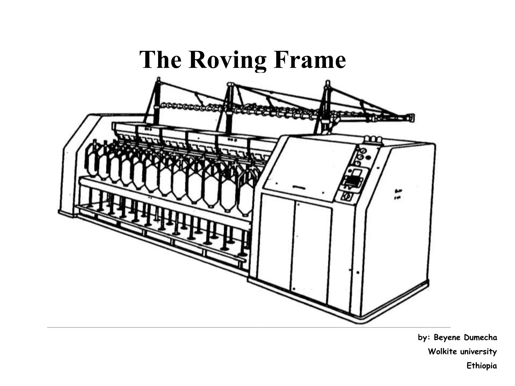
The document discusses the roving frame machine, which comes after the draw frame in the spinning process. The roving frame drafts sliver from draw frame cans into a thin roving strand and applies a light twist. It operates by drafting the sliver, guiding it through the flyer to apply twist, and winding the roved strand onto bobbins. While complicated, the roving frame produces packages of roving suitable for input to the ring frame. Efforts to eliminate this step have not succeeded due to the high drafts required in ring frames.
INTRODUCTION
The ring spinning will continue to be the most widely used form of spinning machine in the near future, because it exhibits significant advantages in comparison with the new spinning processes.
Following are the advantages of ring spinning frame
• It is universally applicable, i.e. any material can be spun to any required count
• It delivers a material with optimum characteristics, especially with regard to structure and strength.
• It is simple and easy to master
• The know-how is well established and accessible for everyone
Warp knitting is a family of knitting methods in which the yarn zigzags along the length of the fabric, i.e., following adjacent columns ("wales") of knitting, rather than a single row ("course"). For comparison, knitting across the width of the fabric is called weft knitting.Warp knitting machines--needles are mounted collectively and rigidly in a horizontal metal bar (the needle bar that runs the full knitting width of the machine).
The chief function of roving frame is the attenuation of sliver.
To draft the sliver to reduce weight per unit length.
Insertion of protective twist in order to hold the fine strand of sliver.
To make conical or tapper shape of the bobbin.
Wind the twisted roving on to the bobbin.
Winding of roving into a package that can be transported, sorted, donned on ring spinning machine.
Differents parts of Simplex Machine and their FunctionsSadia Textile
Fly frame is used to convert the draw frame sliver into a thin material.
This material contain mild amount of twist.
Drafting system stretches the draw frame sliver and make it thin.
The chief functi0n of fly frame is to attenuation of sliver.
Insertion of protective twist in order to hold the fine of sliver, winding of roving into a pac
Drawframe is one of the important machines in yarn spinning line. It is prepared for combining and drawing slivers and removing card irregularities of textile fibres.
NO1 Uk best vashikaran specialist in delhi vashikaran baba near me online vas...Amil Baba Dawood bangali
Contact with Dawood Bhai Just call on +92322-6382012 and we'll help you. We'll solve all your problems within 12 to 24 hours and with 101% guarantee and with astrology systematic. If you want to take any personal or professional advice then also you can call us on +92322-6382012 , ONLINE LOVE PROBLEM & Other all types of Daily Life Problem's.Then CALL or WHATSAPP us on +92322-6382012 and Get all these problems solutions here by Amil Baba DAWOOD BANGALI
#vashikaranspecialist #astrologer #palmistry #amliyaat #taweez #manpasandshadi #horoscope #spiritual #lovelife #lovespell #marriagespell#aamilbabainpakistan #amilbabainkarachi #powerfullblackmagicspell #kalajadumantarspecialist #realamilbaba #AmilbabainPakistan #astrologerincanada #astrologerindubai #lovespellsmaster #kalajaduspecialist #lovespellsthatwork #aamilbabainlahore#blackmagicformarriage #aamilbaba #kalajadu #kalailam #taweez #wazifaexpert #jadumantar #vashikaranspecialist #astrologer #palmistry #amliyaat #taweez #manpasandshadi #horoscope #spiritual #lovelife #lovespell #marriagespell#aamilbabainpakistan #amilbabainkarachi #powerfullblackmagicspell #kalajadumantarspecialist #realamilbaba #AmilbabainPakistan #astrologerincanada #astrologerindubai #lovespellsmaster #kalajaduspecialist #lovespellsthatwork #aamilbabainlahore #blackmagicforlove #blackmagicformarriage #aamilbaba #kalajadu #kalailam #taweez #wazifaexpert #jadumantar #vashikaranspecialist #astrologer #palmistry #amliyaat #taweez #manpasandshadi #horoscope #spiritual #lovelife #lovespell #marriagespell#aamilbabainpakistan #amilbabainkarachi #powerfullblackmagicspell #kalajadumantarspecialist #realamilbaba #AmilbabainPakistan #astrologerincanada #astrologerindubai #lovespellsmaster #kalajaduspecialist #lovespellsthatwork #aamilbabainlahore #Amilbabainuk #amilbabainspain #amilbabaindubai #Amilbabainnorway #amilbabainkrachi #amilbabainlahore #amilbabaingujranwalan #amilbabainislamabad
Overview of the fundamental roles in Hydropower generation and the components involved in wider Electrical Engineering.
This paper presents the design and construction of hydroelectric dams from the hydrologist’s survey of the valley before construction, all aspects and involved disciplines, fluid dynamics, structural engineering, generation and mains frequency regulation to the very transmission of power through the network in the United Kingdom.
Author: Robbie Edward Sayers
Collaborators and co editors: Charlie Sims and Connor Healey.
(C) 2024 Robbie E. Sayers
Welcome to WIPAC Monthly the magazine brought to you by the LinkedIn Group Water Industry Process Automation & Control.
In this month's edition, along with this month's industry news to celebrate the 13 years since the group was created we have articles including
A case study of the used of Advanced Process Control at the Wastewater Treatment works at Lleida in Spain
A look back on an article on smart wastewater networks in order to see how the industry has measured up in the interim around the adoption of Digital Transformation in the Water Industry.
Courier management system project report.pdfKamal Acharya
It is now-a-days very important for the people to send or receive articles like imported furniture, electronic items, gifts, business goods and the like. People depend vastly on different transport systems which mostly use the manual way of receiving and delivering the articles. There is no way to track the articles till they are received and there is no way to let the customer know what happened in transit, once he booked some articles. In such a situation, we need a system which completely computerizes the cargo activities including time to time tracking of the articles sent. This need is fulfilled by Courier Management System software which is online software for the cargo management people that enables them to receive the goods from a source and send them to a required destination and track their status from time to time.
Vaccine management system project report documentation..pdfKamal Acharya
The Division of Vaccine and Immunization is facing increasing difficulty monitoring vaccines and other commodities distribution once they have been distributed from the national stores. With the introduction of new vaccines, more challenges have been anticipated with this additions posing serious threat to the already over strained vaccine supply chain system in Kenya.
Forklift Classes Overview by Intella PartsIntella Parts
Discover the different forklift classes and their specific applications. Learn how to choose the right forklift for your needs to ensure safety, efficiency, and compliance in your operations.
For more technical information, visit our website https://intellaparts.com
Student information management system project report ii.pdfKamal Acharya
Our project explains about the student management. This project mainly explains the various actions related to student details. This project shows some ease in adding, editing and deleting the student details. It also provides a less time consuming process for viewing, adding, editing and deleting the marks of the students.
Hybrid optimization of pumped hydro system and solar- Engr. Abdul-Azeez.pdffxintegritypublishin
Advancements in technology unveil a myriad of electrical and electronic breakthroughs geared towards efficiently harnessing limited resources to meet human energy demands. The optimization of hybrid solar PV panels and pumped hydro energy supply systems plays a pivotal role in utilizing natural resources effectively. This initiative not only benefits humanity but also fosters environmental sustainability. The study investigated the design optimization of these hybrid systems, focusing on understanding solar radiation patterns, identifying geographical influences on solar radiation, formulating a mathematical model for system optimization, and determining the optimal configuration of PV panels and pumped hydro storage. Through a comparative analysis approach and eight weeks of data collection, the study addressed key research questions related to solar radiation patterns and optimal system design. The findings highlighted regions with heightened solar radiation levels, showcasing substantial potential for power generation and emphasizing the system's efficiency. Optimizing system design significantly boosted power generation, promoted renewable energy utilization, and enhanced energy storage capacity. The study underscored the benefits of optimizing hybrid solar PV panels and pumped hydro energy supply systems for sustainable energy usage. Optimizing the design of solar PV panels and pumped hydro energy supply systems as examined across diverse climatic conditions in a developing country, not only enhances power generation but also improves the integration of renewable energy sources and boosts energy storage capacities, particularly beneficial for less economically prosperous regions. Additionally, the study provides valuable insights for advancing energy research in economically viable areas. Recommendations included conducting site-specific assessments, utilizing advanced modeling tools, implementing regular maintenance protocols, and enhancing communication among system components.
Sachpazis:Terzaghi Bearing Capacity Estimation in simple terms with Calculati...Dr.Costas Sachpazis
Terzaghi's soil bearing capacity theory, developed by Karl Terzaghi, is a fundamental principle in geotechnical engineering used to determine the bearing capacity of shallow foundations. This theory provides a method to calculate the ultimate bearing capacity of soil, which is the maximum load per unit area that the soil can support without undergoing shear failure. The Calculation HTML Code included.
Event Management System Vb Net Project Report.pdfKamal Acharya
In present era, the scopes of information technology growing with a very fast .We do not see any are untouched from this industry. The scope of information technology has become wider includes: Business and industry. Household Business, Communication, Education, Entertainment, Science, Medicine, Engineering, Distance Learning, Weather Forecasting. Carrier Searching and so on.
My project named “Event Management System” is software that store and maintained all events coordinated in college. It also helpful to print related reports. My project will help to record the events coordinated by faculties with their Name, Event subject, date & details in an efficient & effective ways.
In my system we have to make a system by which a user can record all events coordinated by a particular faculty. In our proposed system some more featured are added which differs it from the existing system such as security.
2. Introduction
The roving frame is the machine that comes after the draw
frame in short-staple spinning system.
The input is the finisher draw frame sliver in sliver cans and
the output of the roving frame is called roving.
The roving frame is called by various names in the industry
and in the literature.
The machine is called a fly frame or a flyer frame - as it
employs a flyer.
3. The draw frame produces a sliver that already
exhibits all the characteristics required for the
creation of yarn, namely an ordered, clean strand of
fibers lying parallel to one another.
In fact, the roving machine is :
Complicated,
Liable to faults,
Causes defects,
Adds to production costs and delivers a product
that is sensitive both in winding and unwinding.
4. Two principal reasons for the use of roving
frame are:
1) The required high draft in the ring frame (DT = 300 –
500), and
2) Draw frame cans are not convenient for transport and
presentation of feed material to the ring frame.
5. Objectives of draw frame
To draft the sliver to a thin strand,
To impart to the drafted strand a protective twist and
To wind the drafted and twisted roving material onto
a suitable package for further use.
6. Roving frame is a comparatively a slow and complicated
machine.
Not much improvement has been possible in terms of
speeds in comparison with say, a card or a draw frame.
Efforts to eliminate this process have not met with
success so far, at least in the case of ring spinning system.
It is hoped that this machine may become redundant in
the future.
7. Advantages of roving frame
1) The amount of material content in the roving package for its
size is quite substantial; sliver cans cannot hold this amount
of material within the same volume.
2) The handling of roving bobbins and creeling them in the ring
frame are standardised and occupy less space in the ring
frame creel.
The draw frame sliver cannot hope to match the roving
bobbin in this regard.
1) The small amount of twist given to the roving appears to be
more advantageous for good drafting.
8. Operating Sequence
The draw frame sliver cans are arranged in 4 or 6 rows in the
creel zone and the sliver from each can is fed to the drafting
system.
The drafting system drafts the sliver to a fine strand of material
ready for twisting.
The draft usually employed in fly frames ranges from 5 to 20.
Coarser rovings need less and finer rovings need higher drafts.
The delivered roving has a hank (or, count) in the range of about
1s to 3s Ne.
9. The material delivered from the drafting system is led
to the top of the flyer.
From the front roller nip to the flyer top, the material
remains unsupported.
From the top of the flyer, the material is guided
through one of the legs of the flyer; at the bottom of
the leg of the flyer, the material is wound on the
presser (usually two or three turns around the presser
arm).
10. The material is then passed through the eye of the
presser from which point, it can be wound onto the
package.
The strand delivered by the drafting system is thin
and weak.
Therefore, a protective twist - of the order of about 1
to 3 turns per inch is given to the strand before
winding it onto a wooden or plastic package.
11. The flyer imparts twist to the delivered material by
its rotations.
One rotation of flyer imparts one turn of twist to the
delivered material.
The flyer is mounted on the top of a spindle.
The spindle and flyer rotate together.
12. • The flyer rotates at a constant speed.
• The most common speeds employed range from
about 1000 to 1500 revolutions per minute.
• The twisted roving is wound onto the surface of
the bobbin in the form of closely spaced helical
coils.
• Each of the spiral coils is spaced close to each
other i.e. the coils touch each other.
13. To effect winding in this manner, the roving bobbin
is moved up and down.
Once a layer of roving has been wound, the direction
of movement of the bobbin is reversed and a fresh
layer is wound over the previous layer.
The process continues till the bobbin is full.
14. • The bobbins and the associated driving gears are
placed in a bobbin rail; the spindle and the associated
driving gears are housed in the spindle rail.
• The spindle rail is stationary.
• The bobbin rail along with the bobbins moves
vertically up and down during the running of the
machine to enable winding of the material in
traverses.
15. To effect winding of material onto the bobbin, the bobbin
has a rotational speed which is equal to flyer speed plus the
additional rotations for winding.
As each layer is completed, the diameter of the bobbin
increases.
This would mean that the additional rotations required for
winding have to be reduced after the completion of each
layer.
Note that the delivery rate from the drafting system remains
constant.
16. Effect Of Arrangement Of Bobbins In
Two Rows
• In fly frames, the spindles are arranged in two rows (in
a zigzag manner).
• This arrangement is made in order to economise on the
space requirements.
• Though there is a large economy in space, the
arrangement has some technological disadvantages.
17. The free unsupported lengths (L1 & L2) are different for
the two rows of bobbins. (Fig. F 6.3 (a)).
The rolling angles (β) are different (Fig. F 6.3 (b)).
The spinning triangle sizes are different for the two
rows(Fig. F 6.3 (c)).
18. These differences result in:
more complicated design
Operation of the machine is made less convenient
Automation is hindered
uneven twisting
uneven binding of fibres and
ultimately count variation between front and back
rows.
20. The creel
• Above the cans there are several rows of driven
rollers to help the slivers on their way to the drafting
arrangement.
• Guide rollers should run smoothly to avoid false
drafts.
• A perfect drive to the rollers is effected by chains or
shafts.
21. The Drafting Arrangement
A. 3-over-4 drafting arrangement: used relatively rarely since it
gives less drafts.
B. Double apron drafting system with 3/3 or 4/4 (for high drafts)
roller arrangements:
is used in the roving frame since it enables drafts of
20 while holding the fibers more or less under control
during their movements.
22. • Lower rollers are usually fluted.
• Top rollers are rubber coated pressure rollers.
Top roller weighting can be carried out by:
– Spring (all manufacturers)
– Pneumatic pressure (Rieter)
– Spring + magnet
Maximum Total Draft = 20
Minimum Total Draft for cotton = 5 and
for synthetic fibers = 6.
23. Break drafts for cotton = 1.05 – 1.15 (usually 1.1), and for
synthetics and strongly compressed cotton sliver delivered
from high performance draw frames = 1.3.
Break draft affects roving evenness.
24. Aprons are used to guide and transport fibers during
drafting.
• They are made of leather or synthetic rubber.
• They are usually about 1mm thick.
• They should extend as closely as possible to the nip
line of the front rollers.
• The guiding length, referred to as the cradle length,
must be adapted to the staple length.
25. • Material Cradle Length (in mm)
Cotton up to 11/8”; 40mm synthetic fibers -----------------36
Cotton greater than 11/8”; 50mm synthetic fibers ---------43
60mm synthetic fibers ---- ----------------50
26. Spindle and Flyer
The spindle is simply a support and drive element for
the flyer.
The spindle tip is conical and is provided with a slot.
When the flyer is set on the spindle cone, a pin on the
flyer projects into the slot so that the flyer and spindle
are converted into a unit for drive purposes.
27. Functions of the flyer:
1) Inserting twist
Each flyer rotation creates one turn in the roving.
Since the flyer rotation rate is held constant, twist per unit
length of roving depends upon the delivery rate because twist is
given by:
Twist = Flyer rotation rate
Delivery speed
High levels of roving twist always represent production loses and possibly
draft problems in the ring frame.
Low twist levels can cause false drafts or even roving breaks during
bobbin winding.
28. 2). Leading the very sensitive strand from the flyer
top to the package without introducing false
drafts.
This is very difficult task because:
I. The strand has only protective twist and is very
liable to break; and
II. The flyer, along with the roving, is rotating at a high
rate (up to 1500rpm).
29. Cont..
The fiber strand must, therefore, be protected against
strong air currents.
For this purpose, in most roving frames to date, one of
the two flyer legs has been grooved, i.e., open in a
direction opposite to the direction of rotation.
The second full flyer leg serves to balance the
grooved leg.
30. • New designs are no longer provided with this easily accessible,
“service-friendly” groove.
• Instead, they have a very smooth guide tube set into one flyer leg.
• The advantages are:
the strand is completely protected against the air flows and
frictional resistance is significantly reduced so that the strand
can be pulled through with much less force.
These reduce false drafts and strand breaks while allowing high
production speeds.
The disadvantage is that piecing of strand break is difficult.
31. Various designs of the flyer
• The limit on performance of the roving frame is determined by
both the delivery speed and the rotation rate of the flyer.
• Depending upon its form and drive, there are three flyer types:
1. Spindle mounted flyers: Simple as far as design and drive are
concerned. Piecing is easier. However, automation is difficult.
2. Top-mounted (suspended) flyers: Facilitates automation of the
doffing operation, but piecing is difficult.
3. Closed flyers: Reduced spreading of the legs at high operating
speeds.
32. Types of Flyers (a) Spindle mounted (b) Top mounted; (c) closed
flyer
33. The flyer inserts false twist which results in:
Strongly twist roving in the unsupported length
between the drafting arrangement and the flyer.
• Roving breaking rate in the spinning triangle is thus
reduced and fly and lap formation are decreased
34. A more compact roving which increases the capacity of
the bobbin and enables higher flyer speeds.
• The compactness of the roving also enables winding
with higher tension, and
A significant reduction of the difference in roving
fineness between the front and back rows of bobbins.
35. Build up of the bobbin
A roving bobbin is a cylindrical body with tapered ends.
The angle of taper of the ends normally lies between 80o
and 95o (maximum 100o), and depends upon the adherence
of material.
The angle is made as large as possible to wound more
roving onto the package.
However, the angle must be small enough to ensure that the
layers do not slide apart.
37. • Laying down of roving in the package is effected in parallel
layers, i.e., each wrap is laid on wooden or plastics tubes
closely adjacent to the neighboring wrap.
• To wind over the whole length of the tube, the winding
point must be continually shifted.
• This is achieved by:
1) Raising and lowering the flyer or
2) Up and down movement of the tube together
with the bobbin rail (by means of racks or lever).
38.
39. • Variation in bobbin speed originates from the cone
drums.
• When the builder motion shifts the cone belt, the
rotation rate of the lower cone is changed.
• This continuously reducing rotation rate is
transmitted via gearing to the differential and is there
superimposed on the constant speed of the main shaft.
40.
41. • Further gearing then transmits the resultant movement
arising in the differential to the bobbin drive.
• Furthermore, in order to prevent falling away of
individual layers, the bobbin ends are made conical and
consequently the lift of the bobbin rail has to be
reduced after each stroke (layer).
42. For winding and controlled twisting of the roving to a
selected degree, the flyer and the bobbin must have
the same sense of rotation.
However, the bobbin must rotate faster than the flyer
(leading bobbin) or the flyer faster than the bobbin
(leading spindle).
Advantage of leading spindle: With a preset fixed
spindle speed, the operation can be run with lower
bobbin speeds – lower than the spindle speed.
43. Advantages of leading bobbin are:
1. Fewer roving breaks or faultily drafted places at the winding
point because the drive transmission path from the motor to the
spindle is short, whereas that of the bobbin is long
2. No unwinding of the layers during roving breakage and
3. Speed reduction with increasing package diameter.
However, with a leading spindle, the bobbin speed must be
gradually increased with increasing package diameter which
demands more power.
44. Let VB = nB DB
Vs = ns Ds
Then,
Delivery length, L = VB – Vs
= nB DB - ns Ds
But, DB = Ds at the winding point.
Therefore, L = nB D - ns D = (nB - ns) D
Hence, the bobbin speed at any given bobbin
diameter is:
nB = L + ns
D
45. The builder motion
It performs three important tasks during a winding
operation:
1. Shifts the cone belt corresponding to an increase in the
bobbin diameter
2. Reverses the direction of movement of the bobbin rail at
the upper and lower ends of the lift stroke, and
3. Shortens the lift after each layer to form tapered ends on
the bobbins.