Downloaded 149 times


![Winding Principle
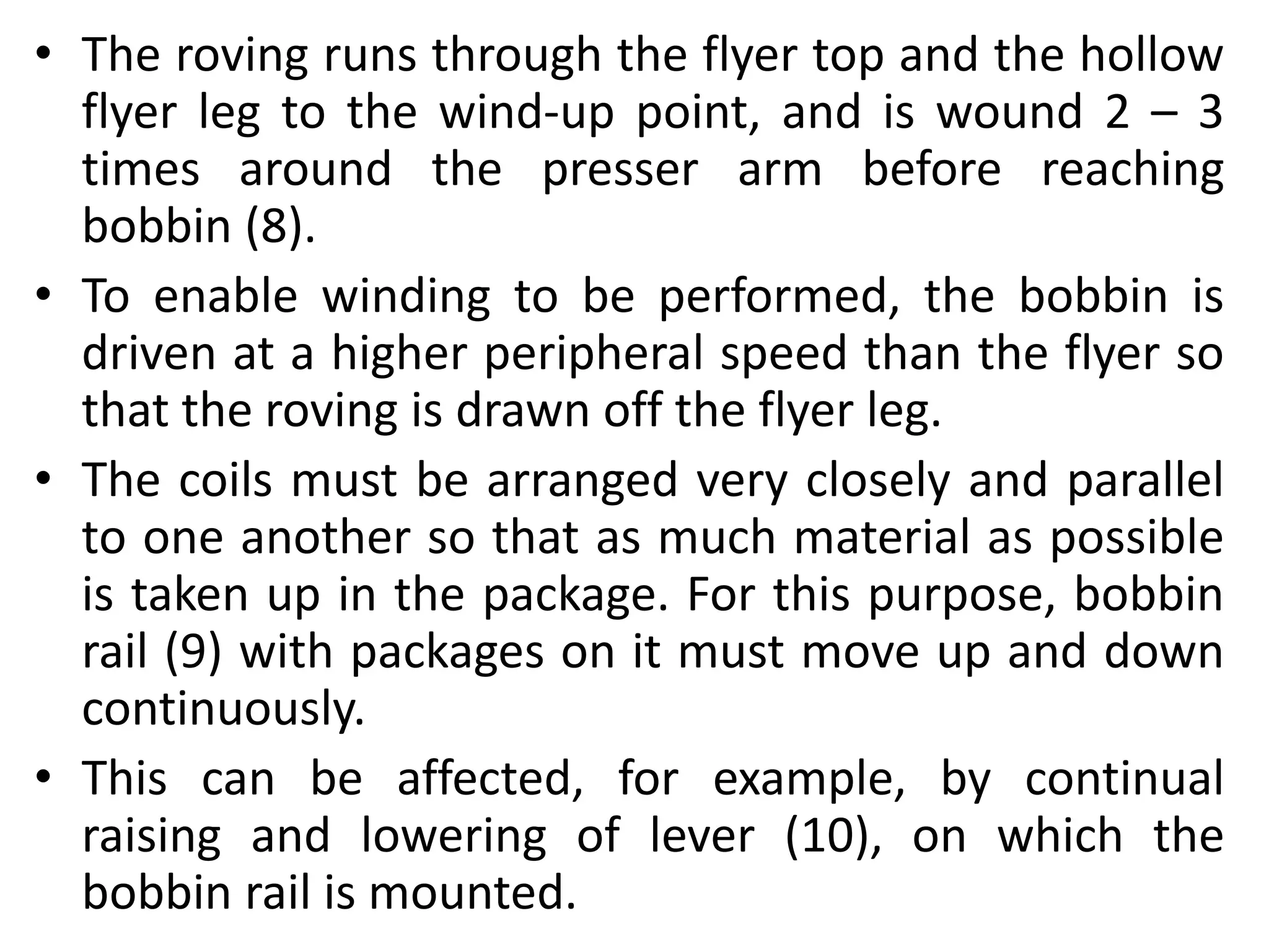
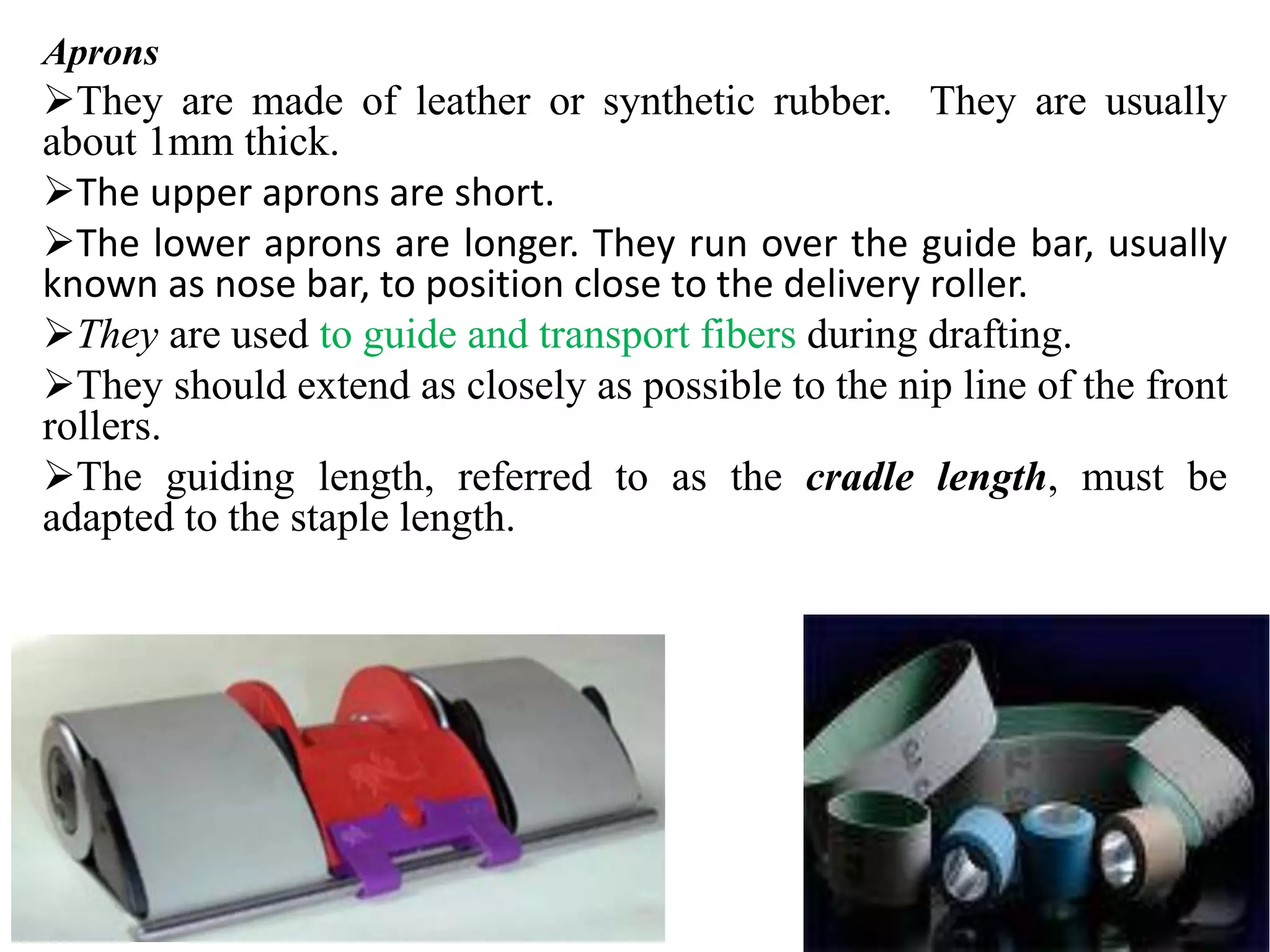
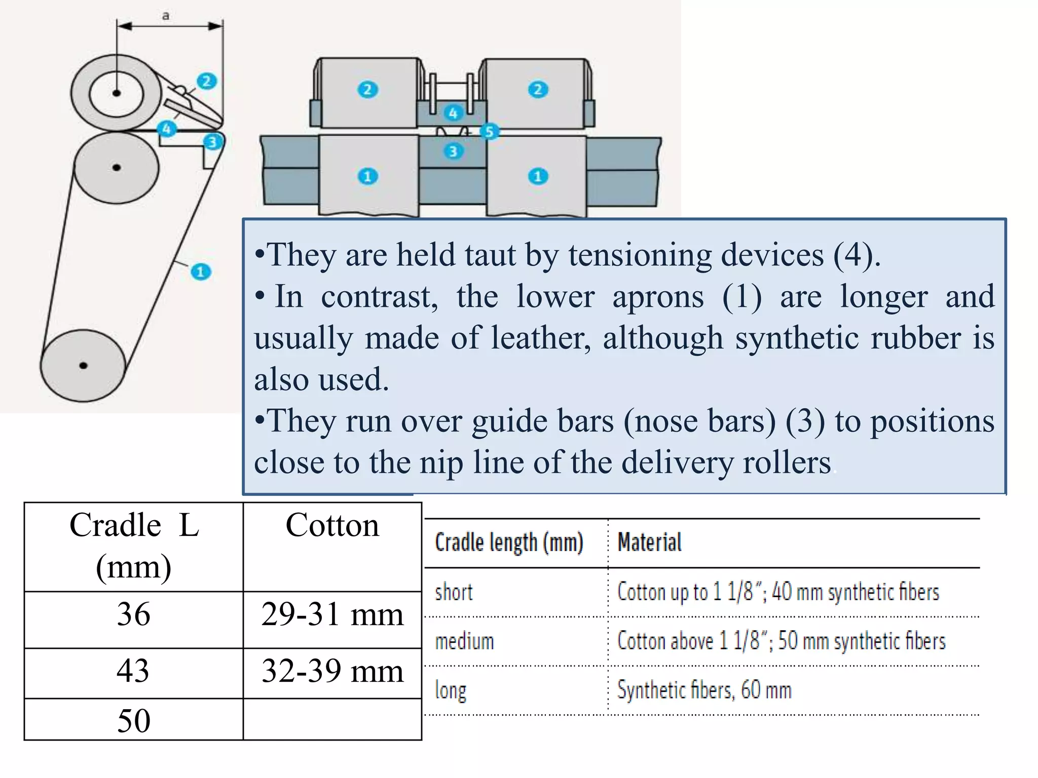
Winding is the process of transferring roving from flyer to
roving bobbin to facilitate subsequent processing.
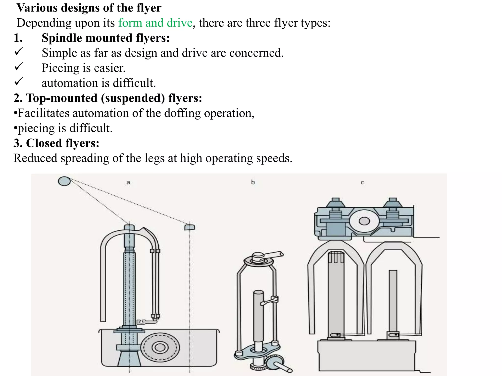
• Cylindrical body with tapered ends.
• Created by building layer upon layer
of parallel coils of roving.
• The angle of taper of the ends is
normally between 80° and 95°.
• Large angle - to wound more roving
onto the package.
• Small angle - to ensure that the
layers do not slide apart. [Slough-off]](https://image.slidesharecdn.com/roving-180515070435/75/Roving-38-2048.jpg)
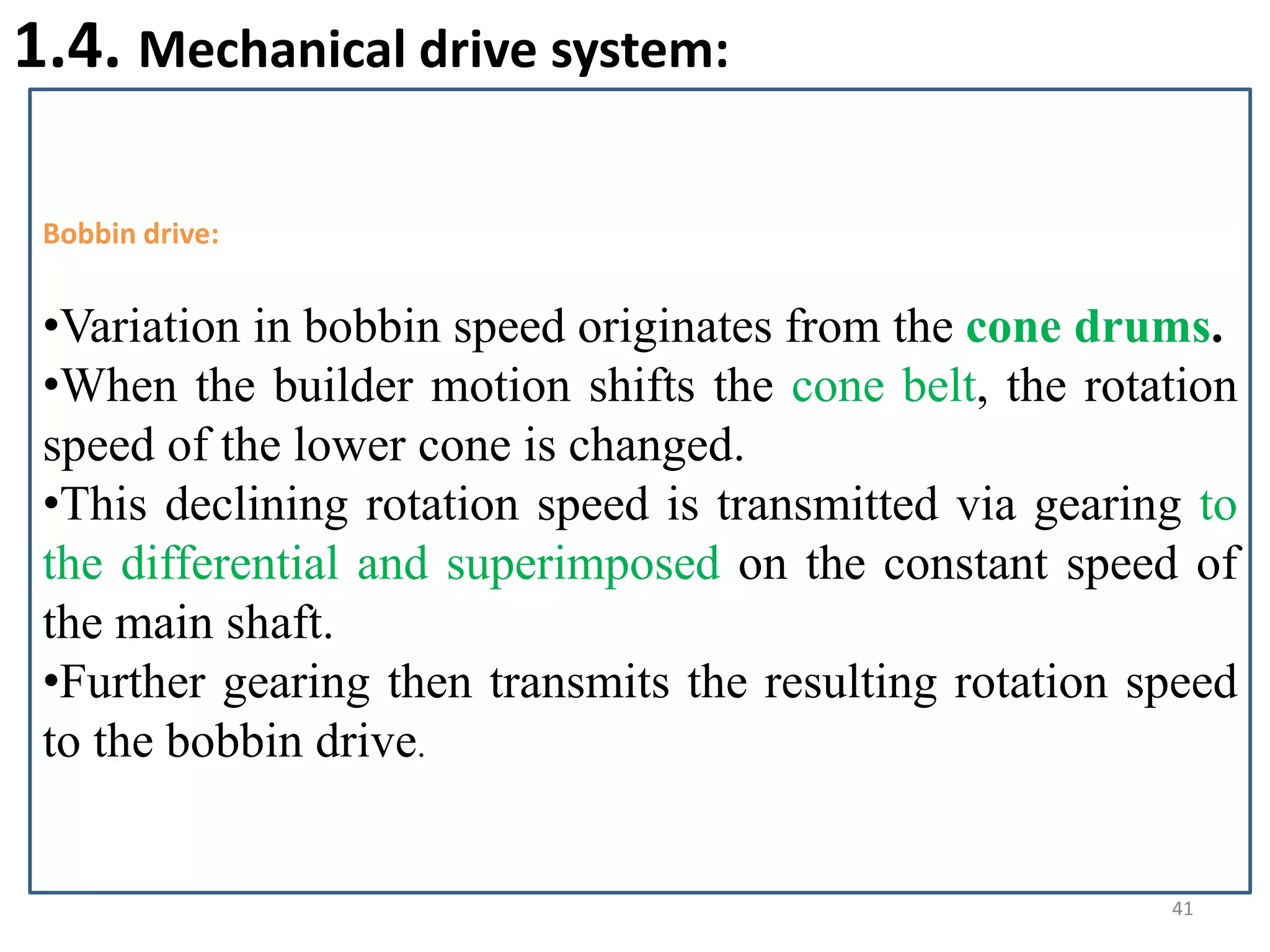
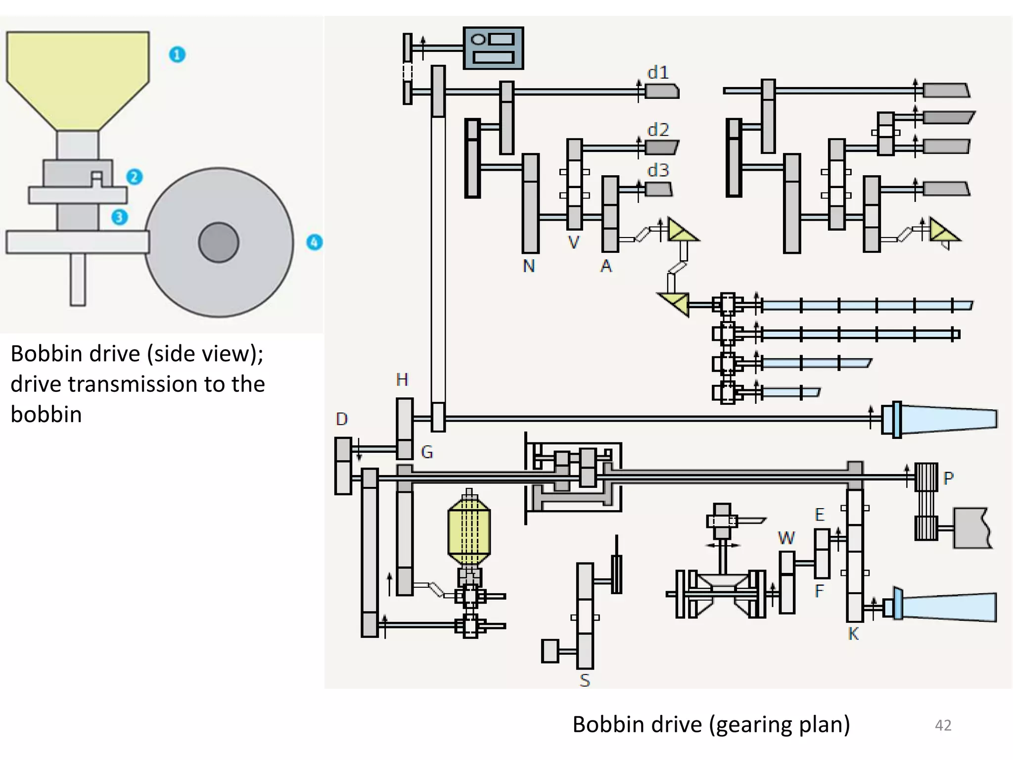
![Mechanical drive systems
Electronic drive system
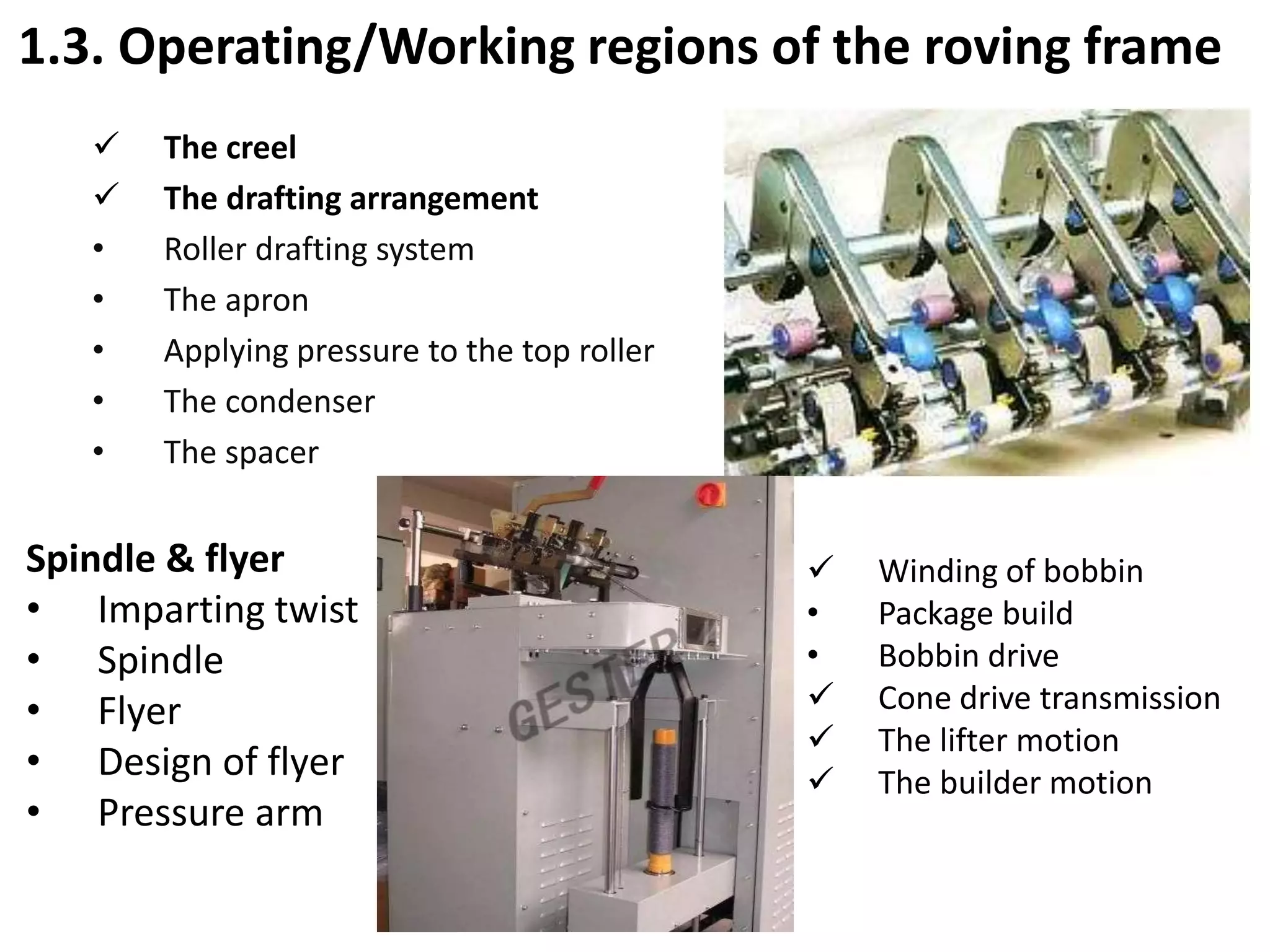
To create the desired shape the following motions
are required;
Bobbin
Rotation – to wind the roving on the roving bobbin
[bobbin speed must be higher than the flyer speed]
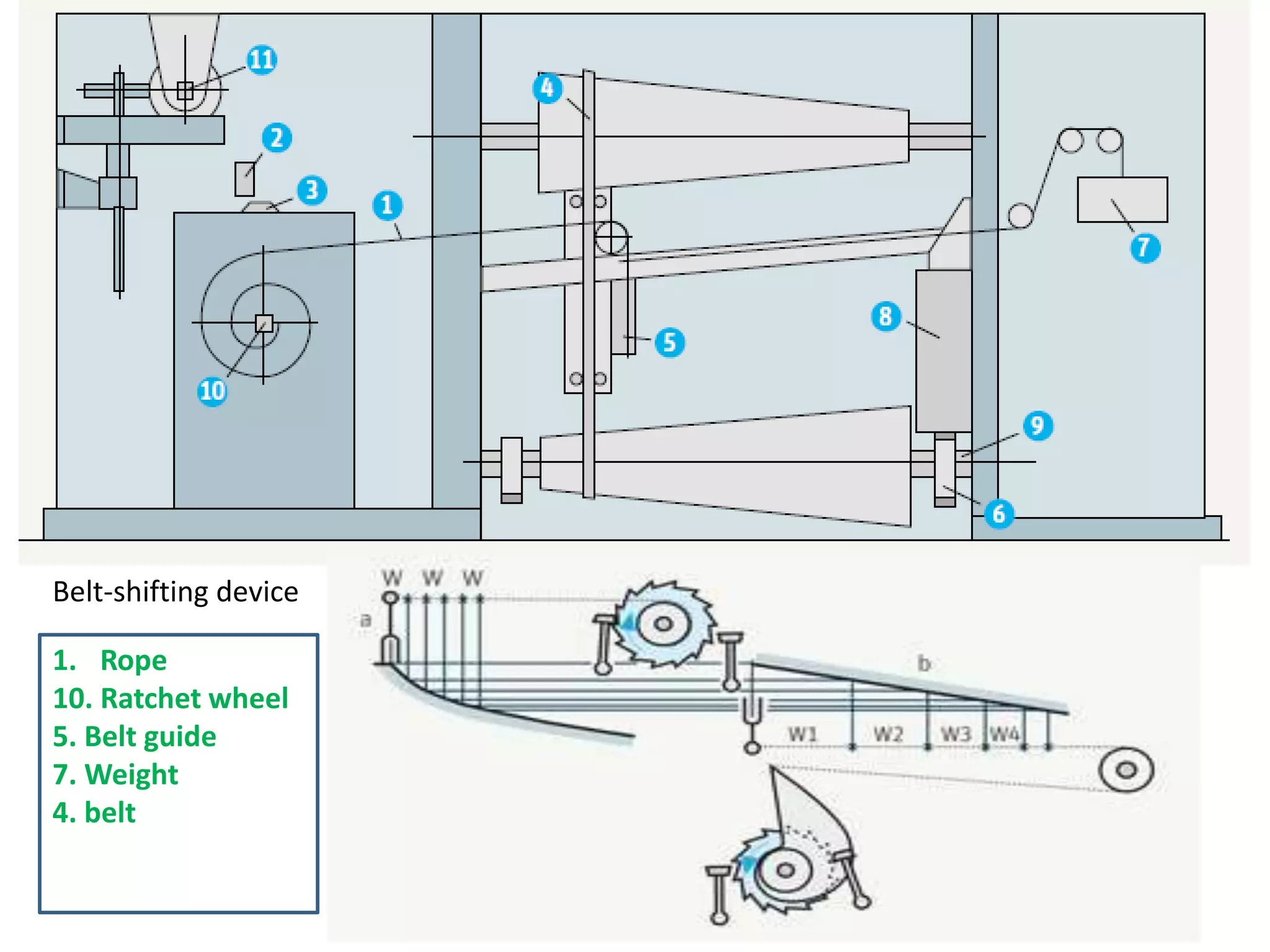
Reduction of rotation by belt shifting– to achieve
constant winding speed
[bobbin dia. increases, the winding on speed must be
decreased-constant]
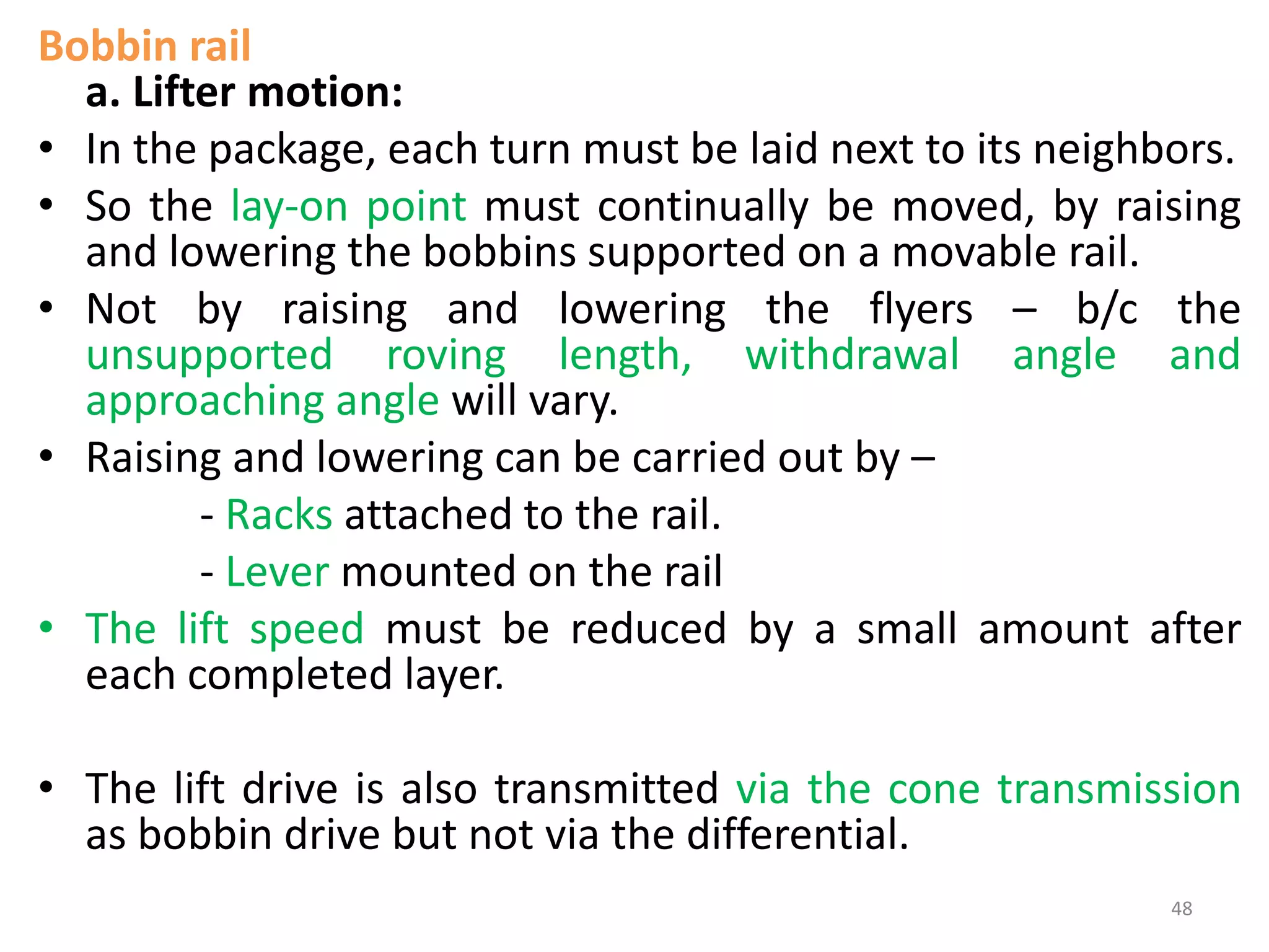
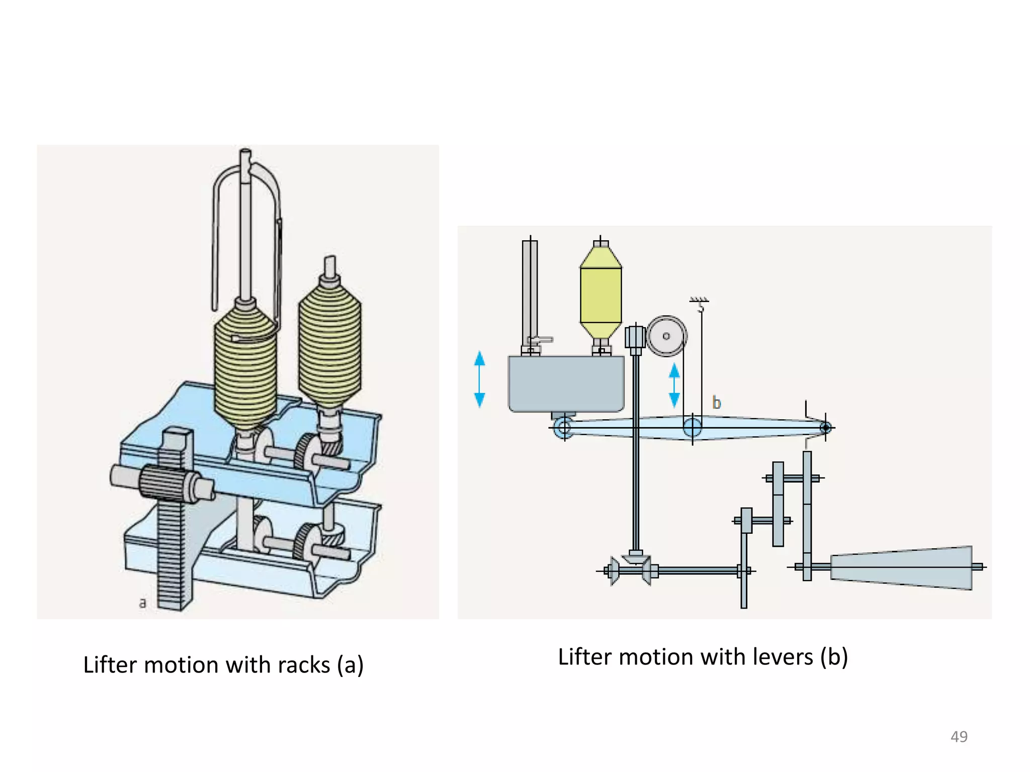
Bobbin rail
Lifter motion - to wind over the whole length of the
tube, the winding point must be continually shifted.
Reversing the direction of movement
Shortening of traverse/stroke after each layer has
been completed – to make tapered ends.](https://image.slidesharecdn.com/roving-180515070435/75/Roving-39-2048.jpg)


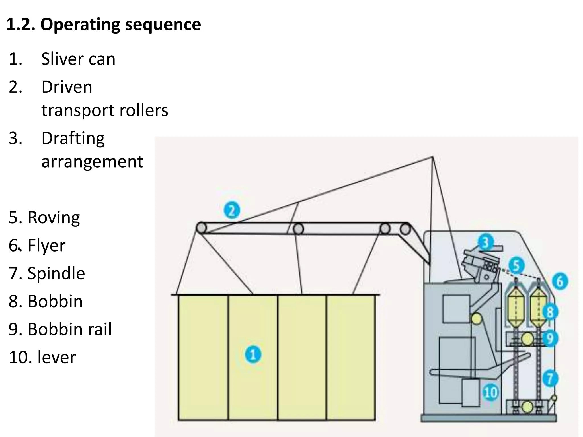
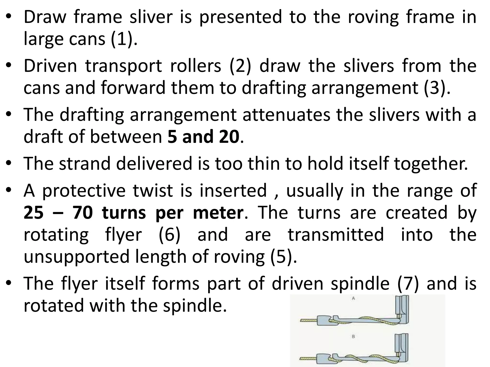
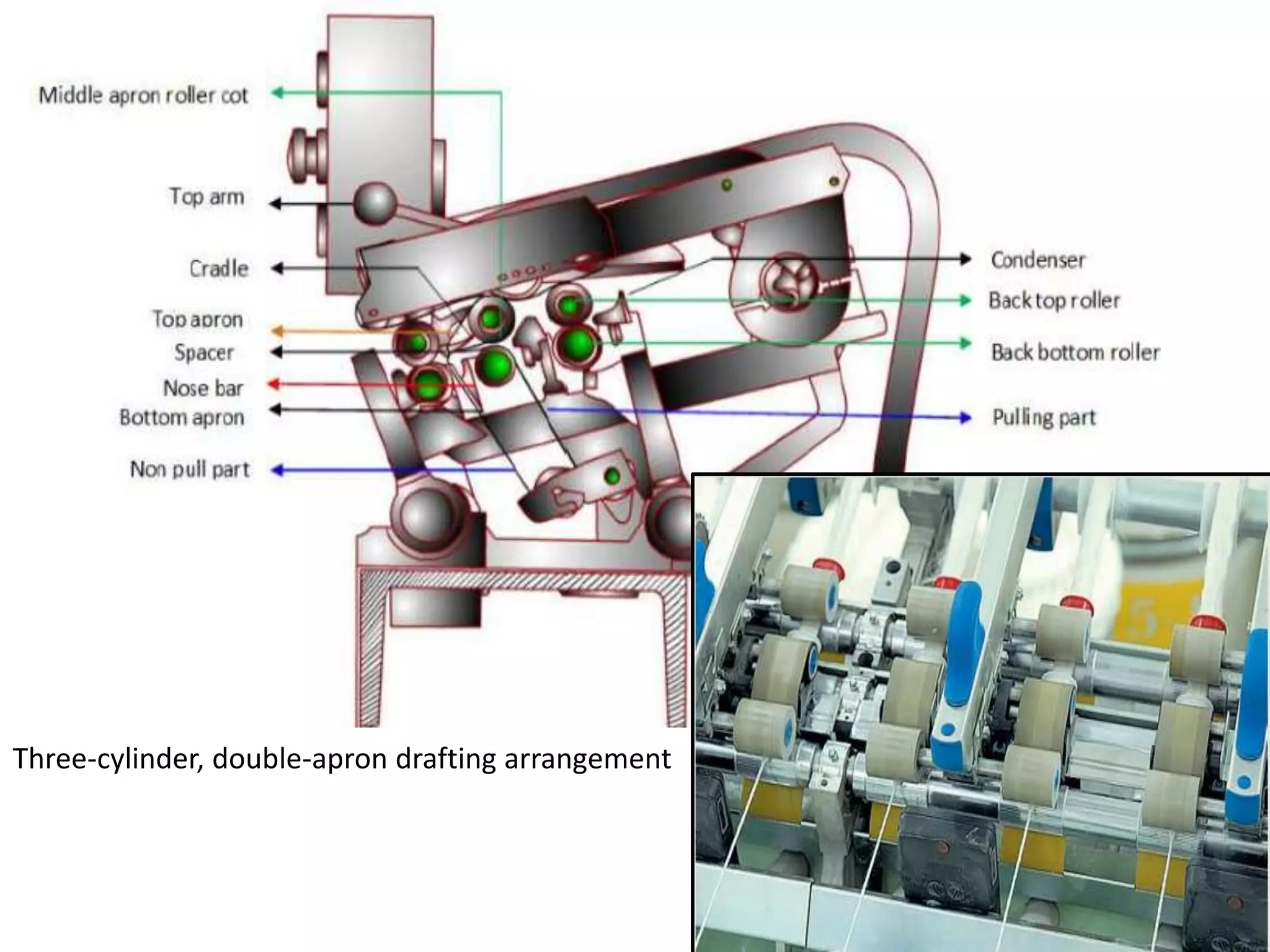
The document discusses the roving frame machine used in textile manufacturing. It begins by explaining the necessity of the roving process and the objectives of the roving frame. The key parts and operating zones of the machine are then described, including the creel, drafting arrangement, twist insertion via the flyer and spindle, and winding of roving onto bobbins. The document provides details on the operating sequence, process parameters like draft and twist levels, and the mechanical drive systems used in the machine.