School of Architecture,Building and Design
Bachelor of Quantity Surveying (Honours)
QSB60103-Site Surveying
Semester 2
Traversing
Name Student ID Marks
Lai Phui Kay 0332782
Kuek Sze TIng 0328259
Sim Tian Xin 0327918
Liew Zhi Zhen 0328769
Felix Yii See Fah 0328491
Foong Zi Quan 0332648
2.
1
Chong Swek Hui0333590
Table of content
Contents Page no.
1.0 Introduction 2
2.0 Types of traversing 3 - 5
3.0 Apparatus used 6 - 9
4.0 Objectives 10
5.0 Steps Using Theodolite 11 - 12
6.0 Field Data 13 - 23
3.
2
1.0 INTRODUCTION
Land surveyingis a process for determining distances and angles between points on
land. Land surveyors use traditional instruments and digital technology to carry out
surveys, data, and maps. This is needed for civil engineering and construction projects.
The history of land surveying can be dated back nearly 3000 years to Ancient Egypt,
during the time when the surveyors subdivided fertile land around Nile River after
annual flooding.
Modern land surveyors, use technology such as robotic total stations and theodolites to
precisely map an area. This collected data can be manipulated by computer aided
design(CAD), building information modeling (BIM) or geographical information systems
(GIS) software.
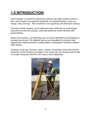
Traversing is that type of survey in which a number of connected survey lines from the
framework and the directions and lengths of the survey lines are measured with the help
of an angle measuring instrument and a tape or chain respectively.
4.
3
2.0 TYPES OFTRAVERSING
There are three types of traverse used in FA survey which are open traverse, closed
traverse, and directional traverse.
Closed Traverse
This traverse starts and ends at stations of known control. There are two types of closed
traverse:
1. closed on the starting point
2. closed on a second known point.
(1) Closed on the starting point.
This type of closed traverse begins at a point of known control, moves through the
various required unknown points, and returns to the same point. This type of closed
traverse is considered to be the second best and is used when both time for survey
and limited survey control are considerations. It provides checks on fieldwork and
computations and provides a basis for comparison to determine the accuracy of the
work performed. This type of traverse does not provide a check on the accuracy of the
starting data or ensure detection of any systematic errors. If a conventional survey
team uses a PADS SCP, they must close on the same point because of the PADS
circular error probable (CEP) and errors in determining assumed data.
(2) Closed on a second known point.
This type of closed traverse begins from a point of known control, moves through the
various required unknown points, and then ends at a second point of known control.
The point on which the survey is closed must be a point established to an equal or
higher order of accuracy than that of the starting point. This is the preferred type of
traverse. It provides checks on fieldwork, computations, and starting control. It also
provides a basis for comparison to determine the accuracy of the work performed.
5.
4
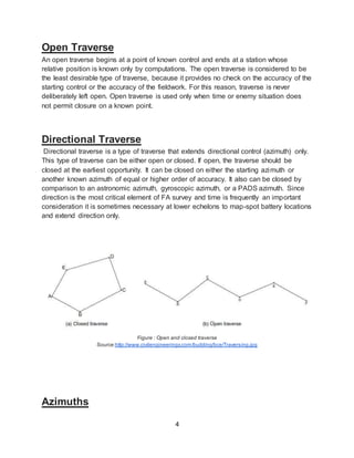
Open Traverse
An opentraverse begins at a point of known control and ends at a station whose
relative position is known only by computations. The open traverse is considered to be
the least desirable type of traverse, because it provides no check on the accuracy of the
starting control or the accuracy of the fieldwork. For this reason, traverse is never
deliberately left open. Open traverse is used only when time or enemy situation does
not permit closure on a known point.
Directional Traverse
Directional traverse is a type of traverse that extends directional control (azimuth) only.
This type of traverse can be either open or closed. If open, the traverse should be
closed at the earliest opportunity. It can be closed on either the starting azimuth or
another known azimuth of equal or higher order of accuracy. It also can be closed by
comparison to an astronomic azimuth, gyroscopic azimuth, or a PADS azimuth. Since
direction is the most critical element of FA survey and time is frequently an important
consideration it is sometimes necessary at lower echelons to map-spot battery locations
and extend direction only.
Figure : Open and closed traverse
Source:http://www.civilengineeringx.com/building/bce/Traversing.jpg
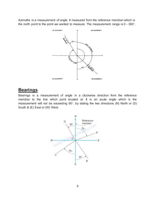
Azimuths
6.
5
Azimuths is ameasurement of angle. It measured from the reference meridian which is
the north point to the point we wanted to measure. The measurement range is 0 - 360°.
Bearings
Bearings is a measurement of angle in a clockwise direction from the reference
meridian to the line which point located at. It is an acute angle which is the
measurement will not be exceeding 90°, by stating the two directions (N) North or (S)
South & (E) East or (W) West.
7.
6
3.0 Apparatus usedfor Traversing
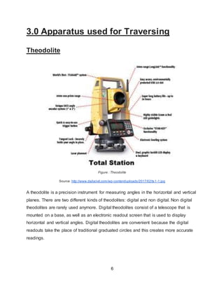
Theodolite
Figure : Theodolite
Source: http://www.dailycivil.com/wp-content/uploads/2017/02/ts1-1.jpg
A theodolite is a precision instrument for measuring angles in the horizontal and vertical
planes. There are two different kinds of theodolites: digital and non digital. Non digital
theodolites are rarely used anymore. Digital theodolites consist of a telescope that is
mounted on a base, as well as an electronic readout screen that is used to display
horizontal and vertical angles. Digital theodolites are convenient because the digital
readouts take the place of traditional graduated circles and this creates more accurate
readings.
8.
7
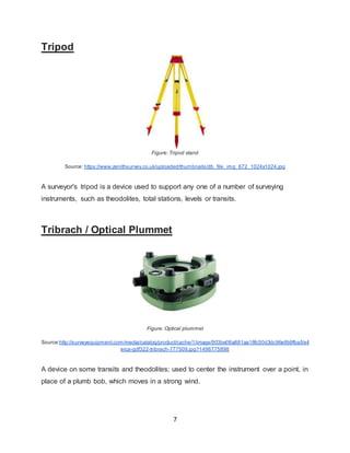
Tripod
Figure: Tripod stand
Source:https://www.zenithsurvey.co.uk/uploaded/thumbnails/db_file_img_672_1024x1024.jpg
A surveyor's tripod is a device used to support any one of a number of surveying
instruments, such as theodolites, total stations, levels or transits.
Tribrach / Optical Plummet
Figure: Optical plummet
Source:http://surveyequipment.com/media/catalog/product/cache/1/image/903be06a881aa18fc50d3dc96e8b9fba/l/e/l
eica-gdf322-tribrach-777509.jpg?1496775898
A device on some transits and theodolites; used to center the instrument over a point, in
place of a plumb bob, which moves in a strong wind.
9.
8
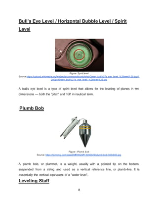
Bull’s Eye Level/ Horizontal Bubble Level / Spirit
Level
Figure: Spirit level
Source:https://upload.wikimedia.org/wikipedia/commons/thumb/e/eb/Green_bull%27s_eye_level_%28level%29.jpg/1
200px-Green_bull%27s_eye_level_%28level%29.jpg
A bull's eye level is a type of spirit level that allows for the leveling of planes in two
dimensions — both the 'pitch' and 'roll' in nautical term.
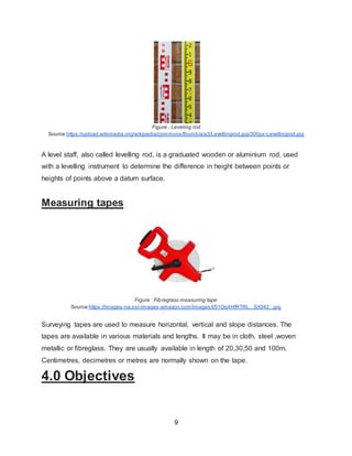
Plumb Bob
Figure : Plumb bob
Source: https://5.imimg.com/data5/MR/NG/MY-4000929/plumb-bob-500x500.jpg
A plumb bob, or plummet, is a weight, usually with a pointed tip on the bottom,
suspended from a string and used as a vertical reference line, or plumb-line. It is
essentially the vertical equivalent of a "water level".
Leveling Staff
10.
9
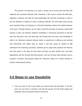
Figure : Levelingrod
Source:https://upload.wikimedia.org/wikipedia/commons/thumb/a/a3/Levellingrod.jpg/300px-Levellingrod.jpg
A level staff, also called levelling rod, is a graduated wooden or aluminium rod, used
with a levelling instrument to determine the difference in height between points or
heights of points above a datum surface.
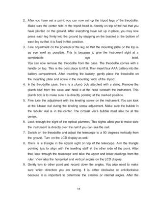
Measuring tapes
Figure : Fibreglass measuring tape
Source:https://images-na.ssl-images-amazon.com/images/I/51Oq4HfRTRL._SX342_.jpg
Surveying tapes are used to measure horizontal, vertical and slope distances. The
tapes are available in various materials and lengths. It may be in cloth, steel ,woven
metallic or fibreglass. They are usually available in length of 20,30,50 and 100m.
Centimetres, decimetres or metres are normally shown on the tape.
4.0 Objectives
11.
10
The purpose oftraversing is to make a survey out of all the point that they had
collected and measured. Besides that, traversing is also used to reduce the field data,
adjusting a traverse and plot the result graphically. Not only that, traversing is used to
find the elevation or height of a pole or building indirectly. The most basic thing and yet
most important thing of traversing is to find the horizontal, vertical and inclined distance
of the point. Through traverse, we are able to learn the principle of running a closed field
traverse. It also can enhance student’s knowledge in traversing procedure so that the
next time they get to the real world they will at least have the basic and knowledge of
what to do. Moreover, students will gain hands on experience in setting up and working
with instruments and collect data for report. It will give guide for student to fully
understand the traversing procedure. Students get to apply both practical and theories
that have learnt in the class for their future and they can also identify error and make
adjustments with the formula that they learned. Last but not least, they will learn how to
compute a traverse and properly adjust the measured values of a closed traverse to
achieve mathematical closure.
5.0 Steps to use theodolite
1. First, you need to set a point where you want to place the theodolite. To set this
point, you can drive a surveyor’s nail onto the ground. So that all the angles and
distances will be measured based on this point.
12.
11
2. After youhave set a point, you can now set up the tripod legs of the theodolite.
Make sure the center hole of the tripod head is directly on top of the nail that you
have planted on the ground. After everything have set up in place, you may now
press each leg firmly into the ground by stepping on the bracket at the bottom of
each leg so that it is fixed in that position.
3. Fine adjustment on the position of the leg so that the mounting plate on the top is
as eye level as possible. This is because to give the instrument sight at a
comfortable eye level.
You can now remove the theodolite from the case. The theodolite comes with a
handle on top. This is the best place to lift it. Then insert four AAA battery into the
battery compartment. After inserting the battery, gently place the theodolite on
the mounting plate and screw in the mounting knob of the tripod.
4. In the theodolite case, there is a plumb bob attached with a string. Remove the
plumb bob from the case and hook it at the hook beneath the instrument. This
plumb bob is to make sure it is directly pointing at the marked position.
5. Fine tune the adjustment with the leveling screw on the instrument. You can look
at the tubular vial during the leveling screw adjustment. Make sure the bubble in
the tubular vial is in the center. The circular vial’s bubble must also be at the
center.
6. Look through the sight of the optical plummet. This sights allow you to make sure
the instrument is directly over the nail if you can see the nail.
7. Switch on the theodolite and adjust the telescope to a 90 degrees vertically from
the ground. Turn on the LCD display as well.
8. There is a triangle in the optical sight on top of the telescope. Aim the triangle
pointing tips to align with the levelling staff at the other side of the point. After
that, look through the telescope and take the upper and lower readings from the
ruler. View also the horizontal and vertical angles on the LCD display.
9. Gently turn to other point and record down the angles. You also need to make
sure which direction you are turning. It is either clockwise or anticlockwise
because it is important to determine the external or internal angles. After the
13.
12
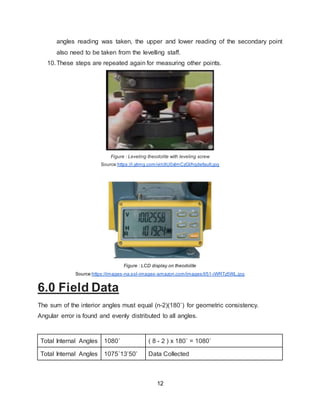
angles reading wastaken, the upper and lower reading of the secondary point
also need to be taken from the levelling staff.
10.These steps are repeated again for measuring other points.
Figure : Leveling theodolite with leveling screw
Source:https://i.ytimg.com/vi/c9U0xlmCzGI/hqdefault.jpg
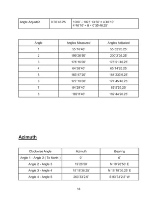
Figure : LCD display on theodolite
Source:https://images-na.ssl-images-amazon.com/images/I/51-iWRTz5WL.jpg
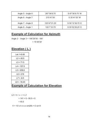
6.0 Field Data
The sum of the interior angles must equal (n-2)(180˚) for geometric consistency.
Angular error is found and evenly distributed to all angles.
Total Internal Angles 1080˚ ( 8 - 2 ) x 180˚ = 1080˚
Total Internal Angles 1075˚13’50’ Data Collected
14
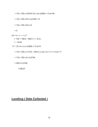
Angle 5 -Angle 6 267˚56’8.75’ S 87˚56’8.75’ W
Angle 6 - Angle 7 215˚41’55’ S 35˚41’55’ W
Angle 7 - Angle 8 120˚47’21.25’ S 59˚12’38.75’ E
Angle 8 - Angle 1 124˚7’33.75’ S 55˚52’26.25’ E
Example of Calculation for Azimuth
Angle 2 - Angle 3 = 199˚26’50 - 180˚
= 19˚26’50’
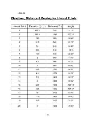
Elevation ( L )
Let 1=0.00
L2 = 45.5
L3 = 71.5
L4 = 157.5
L5 = 209.5
L6 = 219
L7 = -6.5
L8 = -16.43
Example of Calculation for Elevation
L2 = h + v - r + L1
= 141 + 0 - 95.5 + 0
= 45.5
V = 1/2 x k x s x sin(2θ) + C sin θ
16.
15
= 1/2 x100 x (100-91.5) x sin (2x90) + 0 sin 90
= 1/2 x 100 x 8.5 x sin180 + 0
= 1/2 x 100 x 8.5 x 0
= 0
L8 = h + v - r + L7
= 130 + 168.5 - 308.5 + ( - 6.5 )
= - 16.43
V = 1/2 x k x s x sin(2θ) + C sin θ
= 1/2 x 100 x ( 313.0 - 304.0 ) x sin ( 2 x 11 ) + 0 sin 11
= 1/2 x 100 x 9 x 0.3746
= 450 x 0.3746
=168.57
Leveling ( Data Collected )
17.
16
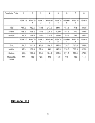
Theodolite Point 12 3 4 5 6 7 8
Point 1-8 Point 2-
1
Point 3-
2
Point 4-
3
Point 5-
4
Point 6-
5
Point 7-
6
Point 8-
7
Top 169.0 182.5 149.5 243.5 214.5 157.5 36.5 145.0
Middle 156.5 178.5 147.5 236.5 205.0 151.5 33.0 141.0
Bottom 144.5 174.0 142.5 229.5 195.0 145.5 29.5 136.5
Point 1-2 Point 2-
3
Point 3-
4
Point 4-
5
Point 5-
6
Point 6-
7
Point 7-
8
Point 8-
1
Top 100.0 111.5 46.0 104.0 146.5 378.0 313.0 139.0
Middle 95.5 109.0 39.0 94.0 140.5 374.5 308.5 126.0
Bottom 91.5 106.5 31.5 104.0 135.5 371.5 304.0 173.5
Theodolite
Height
141 135 125 146 150 149 130 144
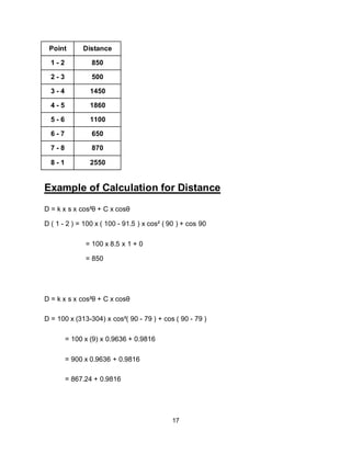
Distance ( D )
18.
17
Point Distance
1 -2 850
2 - 3 500
3 - 4 1450
4 - 5 1860
5 - 6 1100
6 - 7 650
7 - 8 870
8 - 1 2550
Example of Calculation for Distance
D = k x s x cos²θ + C x cosθ
D ( 1 - 2 ) = 100 x ( 100 - 91.5 ) x cos² ( 90 ) + cos 90
= 100 x 8.5 x 1 + 0
= 850
D = k x s x cos²θ + C x cosθ
D = 100 x (313-304) x cos²( 90 - 79 ) + cos ( 90 - 79 )
= 100 x (9) x 0.9636 + 0.9816
= 900 x 0.9636 + 0.9816
= 867.24 + 0.9816
19
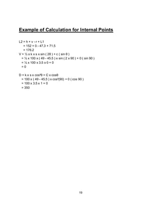
Example of Calculationfor Internal Points
L2 = h + v - r + L1
= 152 + 0 - 47.3 + 71.5
= 176.2
V = ½ x k x s x sin ( 2θ ) + c ( sin θ )
= ½ x 100 x ( 49 - 45.5 ) x sin ( 2 x 90 ) + 0 ( sin 90 )
= ½ x 100 x 3.5 x 0 + 0
= 0
D = k x s x cos²θ + C x cosθ
= 100 x ( 49 - 45.5 ) x cos²(90) + 0 ( cos 90 )
= 100 x 3.5 x 1 + 0
= 350
21.
20
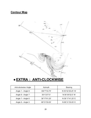
Contour Map
●EXTRA :ANTI-CLOCKWISE
Anti-clockwise Angle Azimuth Bearing
Angle 1 - Angle 8 304°7'33.75' N 55˚52’26.25’ W
Angle 8 - Angle 7 301°23'7.5' N 58˚36’52.5’ W
Angle 7 - Angle 6 36°17'41.25' N 36˚17’41.25’ E
Angle 6 - Angle 5 88°31'55.05' N 88˚31’55.05’ E
22.
21
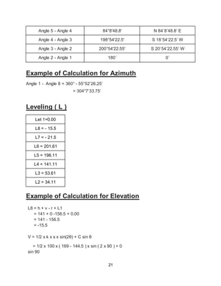
Angle 5 -Angle 4 84°8'48.8' N 84˚8’48.8’ E
Angle 4 - Angle 3 198°54'22.5' S 18˚54’22.5’ W
Angle 3 - Angle 2 200°54'22.55' S 20˚54’22.55’ W
Angle 2 - Angle 1 180˚ 0˚
Example of Calculation for Azimuth
Angle 1 - Angle 8 = 360° - 55°52’26.25’
= 304°7’33.75’
Leveling ( L )
Let 1=0.00
L8 = - 15.5
L7 = - 21.5
L6 = 201.61
L5 = 196.11
L4 = 141.11
L3 = 53.61
L2 = 34.11
Example of Calculation for Elevation
L8 = h + v - r + L1
= 141 + 0 -156.5 + 0.00
= 141 - 156.5
= -15.5
V = 1/2 x k x s x sin(2θ) + C sin θ
= 1/2 x 100 x ( 169 - 144.5 ) x sin ( 2 x 90 ) + 0
sin 90
23.
22
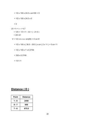
= 1/2 x100 x 24.5 x sin180 + 0
= 1/2 x 100 x 24.5 x 0
= 0
L6 = h + v - r +L7
= 125 + 131.11 - 33 + ( - 21.5 )
= 201.61
V = 1/2 x k x s x sin(2θ) + C sin θ
= 1/2 x 100 x ( 36.5 - 29.5 ) x sin ( 2 x 11 ) + 0 sin 11
= 1/2 x 100 x 7 x 0.3746
= 350 x 0.3746
= 131.11
Distance ( D )
Point Distance
1 - 8 2450
8 - 7 850
7 - 6 675.5
24.
23
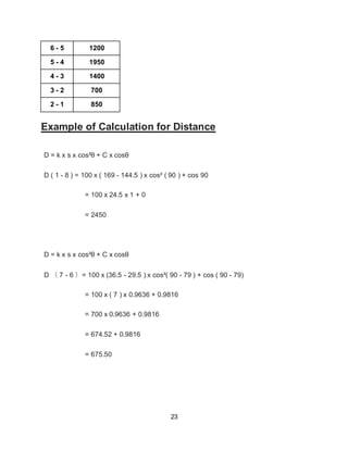
6 - 51200
5 - 4 1950
4 - 3 1400
3 - 2 700
2 - 1 850
Example of Calculation for Distance
D = k x s x cos²θ + C x cosθ
D ( 1 - 8 ) = 100 x ( 169 - 144.5 ) x cos² ( 90 ) + cos 90
= 100 x 24.5 x 1 + 0
= 2450
D = k x s x cos²θ + C x cosθ
D ( 7 - 6 )= 100 x (36.5 - 29.5 ) x cos²( 90 - 79 ) + cos ( 90 - 79)
= 100 x ( 7 ) x 0.9636 + 0.9816
= 700 x 0.9636 + 0.9816
= 674.52 + 0.9816
= 675.50