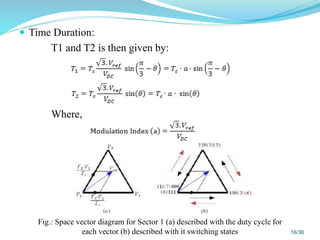
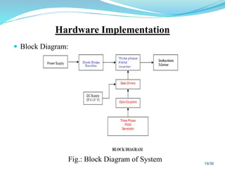
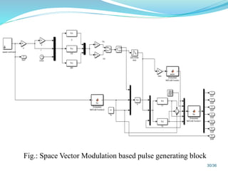
This document presents a project on controlling the speed of a three-phase induction motor using space vector pulse width modulation (SVPWM). It discusses the aims of developing a simulation and prototype model for V/f speed control. It describes different PWM techniques and speed control methods for induction motors. It also explains the concepts of space vector modulation including voltage vectors, reference vectors, sector selection, and duty cycle calculation. The hardware and software implementation are outlined, including the inverter design, gate driver circuit, and MATLAB simulation model. Test results demonstrate varying the motor speed by adjusting the voltage and frequency while maintaining a constant V/f ratio.


![References
[1] Programable laboratory invertor and space vector pwmIng. Pavel GAJDŮŠEK, Doctoral
Degree Programme (2) Dept. of Electrical Power Engineering, FEEC, VUT E-mail:
xgajdu02@stud.feec.vutbr.cz Supervised by: Prof. Jiří Skalický
[2] SVPWM Based Speed Control of Induction Motor Drive with Using V/F Control Based 3-
Level Inverter 1Srinivasa Rao Maturu* and 2Avinash Vujji VSRD-IJEECE, Vol. 2 (7), 2012,
421-437.
[3] A Space Vector Modulation Control Algorithm for VSI Multi-Level Converters A. Cataliotti, F.
Genduso, G. Ricco Galluzzo Dipartimento di Ingegneria eletrica Università degli Studi di
Palermo: acataliotti@ieee.org; genduso@diepa.unipa.it; ricco@diepa.unipa.it
[4] Modelling and simulation of a multilevel inverter using space vector modulation technique
ayse kocalmis1 sed at sünter
[5] IEEE transactions on industrial electronics, vol. 57, no. 7, july 2010 2473 Conventional Space-
Vector Modulation Techniques Versus the Single-Phase Modulator for Multilevel Converters
[6] Optimised Space Vector Switching Sequences for Multilevel Inverters B. P. McGrath*, D.G.
Holmes* and T. A. Lipo**
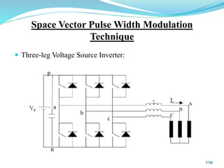
[7] 2 Space vector modulation for three-leg voltage source inverters
[8] IEEE transactions on industrial electronics, vol. 49, no. 1, February 2002 Relationship between
Space-Vector Modulation and Three-Phase Carrier-Based PWM: A Comprehensive Analysis
Keliang Zhou and Danwei Wang, Member, IEEE
34/36](https://image.slidesharecdn.com/imsvmslideshare-200222072413/85/Speed-control-of-IM-using-Space-Vector-Modulation-34-320.jpg)
![[9] Comparison between two modulation techniques for three phase inverters from a hardware
implementation point of view by bogdan alecsa ∗ and alexandru onea
[10]IECON'01: The 27th Annual Conference of the IEEE Industrial Electronics Society space
vector modulation – An Introduction = Tutorial at IECON2001 = Dorin O. Neacsu
Correspondence Address: Satcon Corporation, 161 First Street, Cambridge, MA 02142, Email
neacsu@earthlink.com
[11]5th International Advanced Technologies Symposium (IATS’09), May 13-15, 2009, Karabuk,
Turkey © IATS’09, Karabük University, Karabük, Turkey Three-dimensional space-vector
modulation algorithm for all types of multilevel converters using abc coordinate
[12]Multilevel Multiphase Space Vector PWM Algorithm Applied to Three-Phase Converters O´
scar Lo´pez, Jacobo A´ lvarez, Jesu´s Doval-Gandoy, Francisco Freijedo, Andre´s Nogueiras
and Carlos M. Pen˜alver Electronics Technology Department University of Vigo
[13]G.Sambasiva Rao et al. / International Journal of Engineering Science and Technology
(IJEST) A comprehensive analysis of space vector pwm technique based on placement of zero-
space vector g.sambasiva rao
[14]Harmonic Effects of Space Vector Modulation on Induction Motor Performance Jennifer
Vining Dept. of Electrical and Computer Engineering 1415 Engineering Drive Madison, WI
53706
[15]National Power Electronics Conference 2010 Novel Switching Sequences for a Space Vector
Modulated Three-Level Inverter
35/36](https://image.slidesharecdn.com/imsvmslideshare-200222072413/85/Speed-control-of-IM-using-Space-Vector-Modulation-35-320.jpg)