Downloaded 1,003 times

![BIBLIOGRAPHY [1]. Hind Djeghloud and Hocine Benalla, “Space Vector Pulse Width Modulation Applied to The Three-Level Voltage Inverter”, 5th International Conference on Technology and Automation ICTA’05, Thessaloniki, Greece, Oct 2010. [2]. Jin-woo Jung, “Space Vector PWM Inverter”, The Ohio State University, February, 2008. [3]. Jae Hyeong Seo; Chang Ho Choi; Dong Seok Hyun, “A New Simplified space-Vector PWM Method for Three-Level Inverters”, IEEE Transactions on Power Electronics, Volume 16, Issue 4, Jul 2010, Pages 545 - 550 [4]. Muhammad H.Rashid “Power Electronics Circuits, devices, and Applications”, Prentice-Hall of India Private Limited, Third Edition, 2004. [5]. “the adaptive space vector pwm for four switch three phase inverter fed induction motor with dc – link voltage imbalance” by Hong Hee Lee*, Phan Quoc Dzung**, Le Dinh Khoa**, Le Minh Phuong**, Huynh Tan Thanh***School of Electrical Engineering, University of Ulsan Ulsan, Korea. [6]. P.S.Bimbhra, “Power Electronics”, Khanna publications. [7]. Overview of MATLAB Simulink Http://www.mathworks.com/products/simulink/description/overview.shtml](https://image.slidesharecdn.com/projectreview-1-110413033108-phpapp02/75/space-vector-PWM-for-2-leg-inverter-24-2048.jpg)


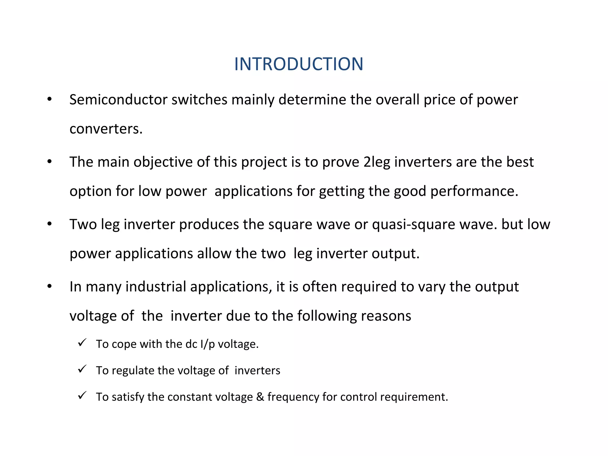
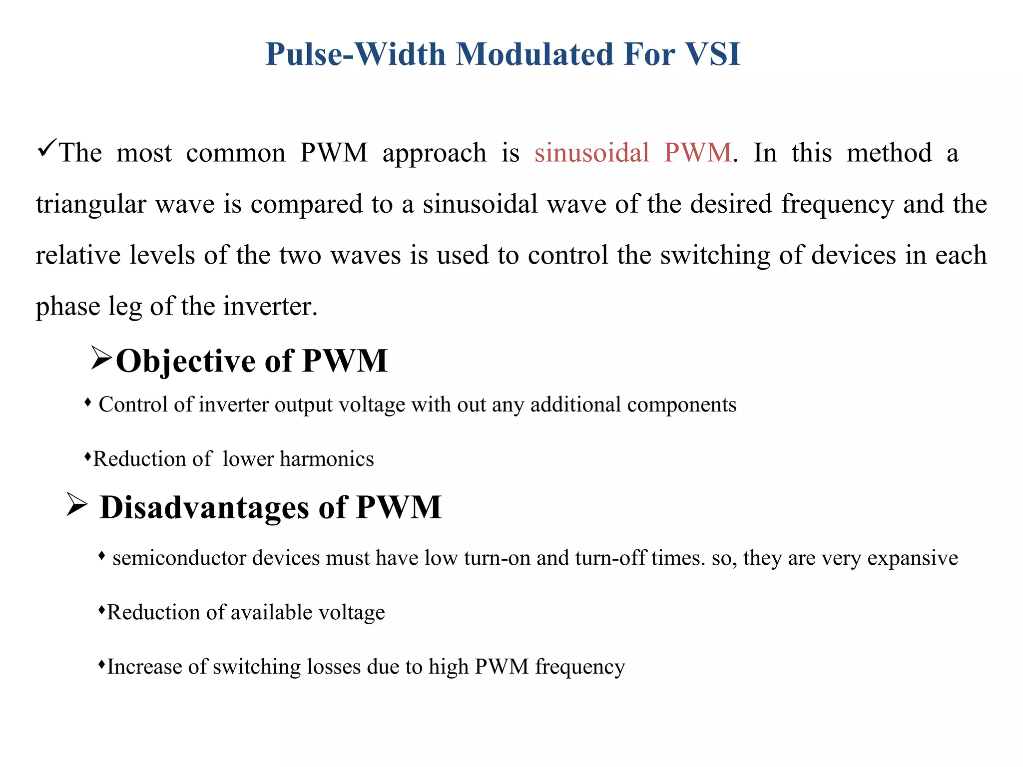
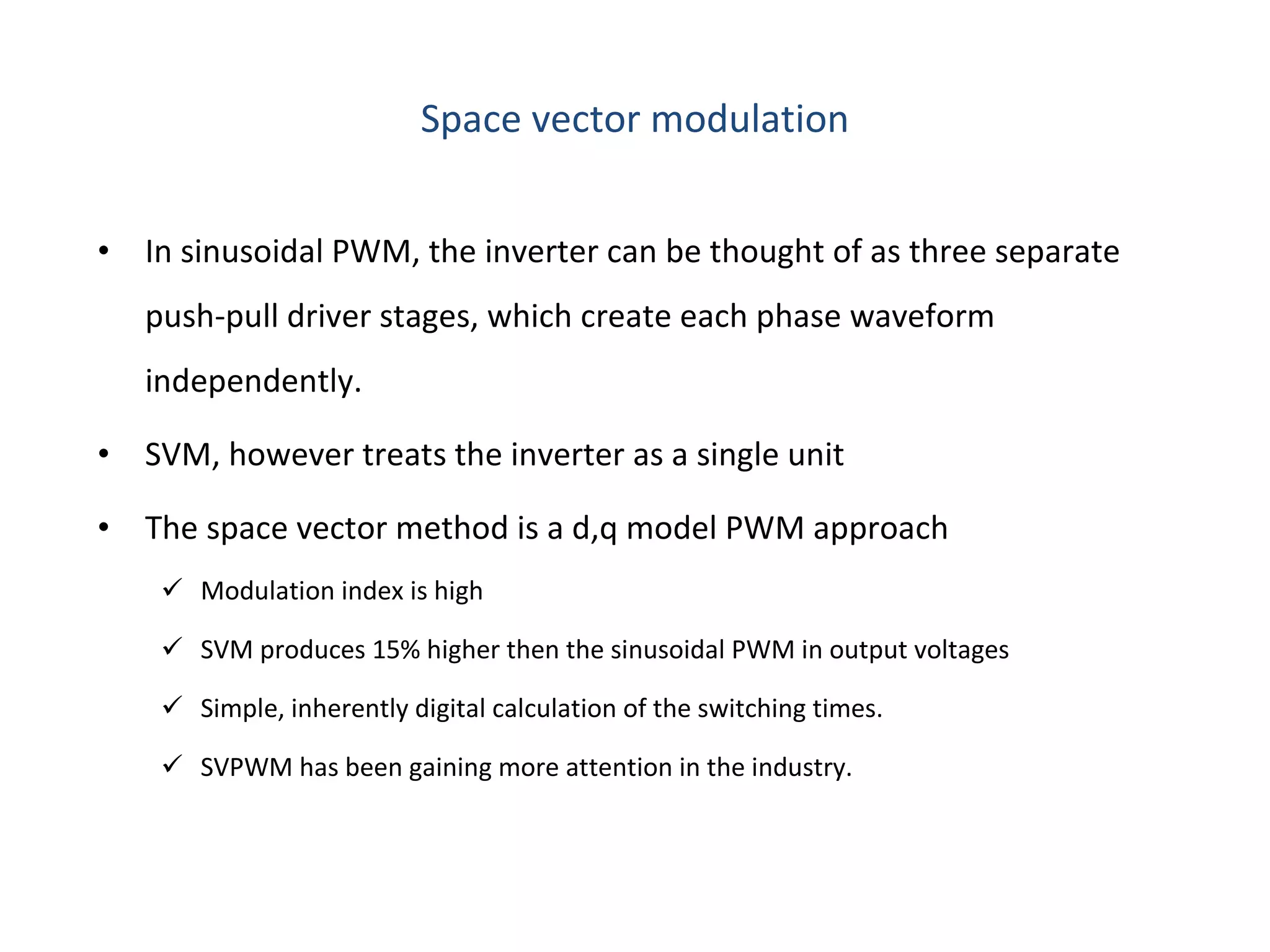
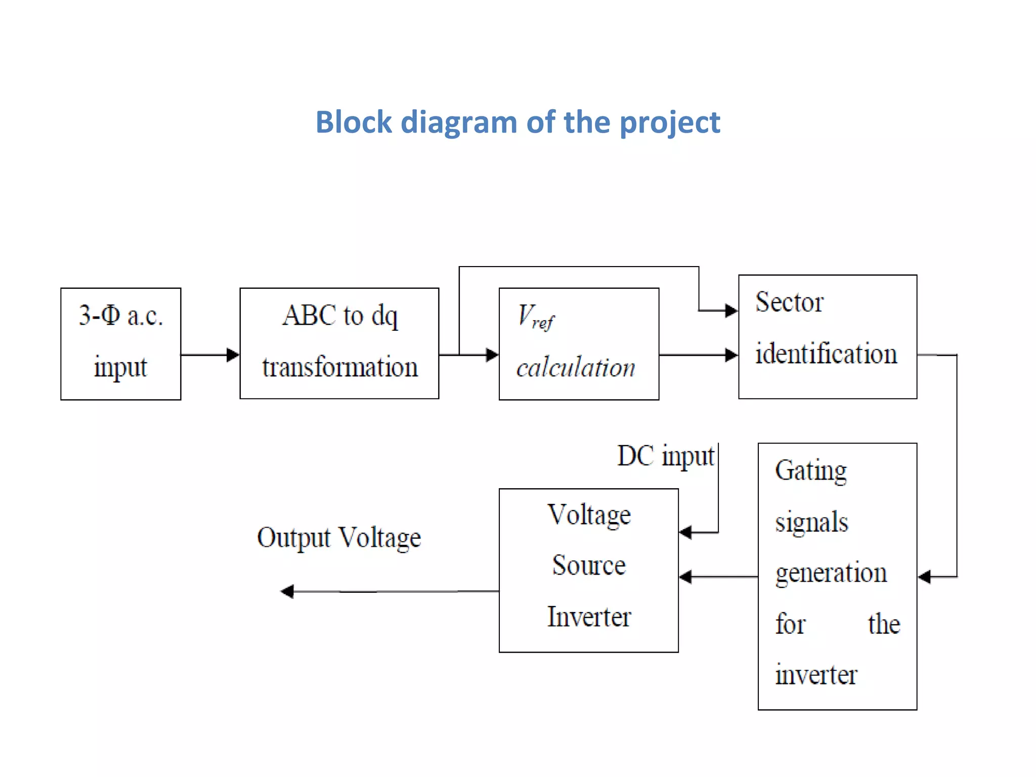
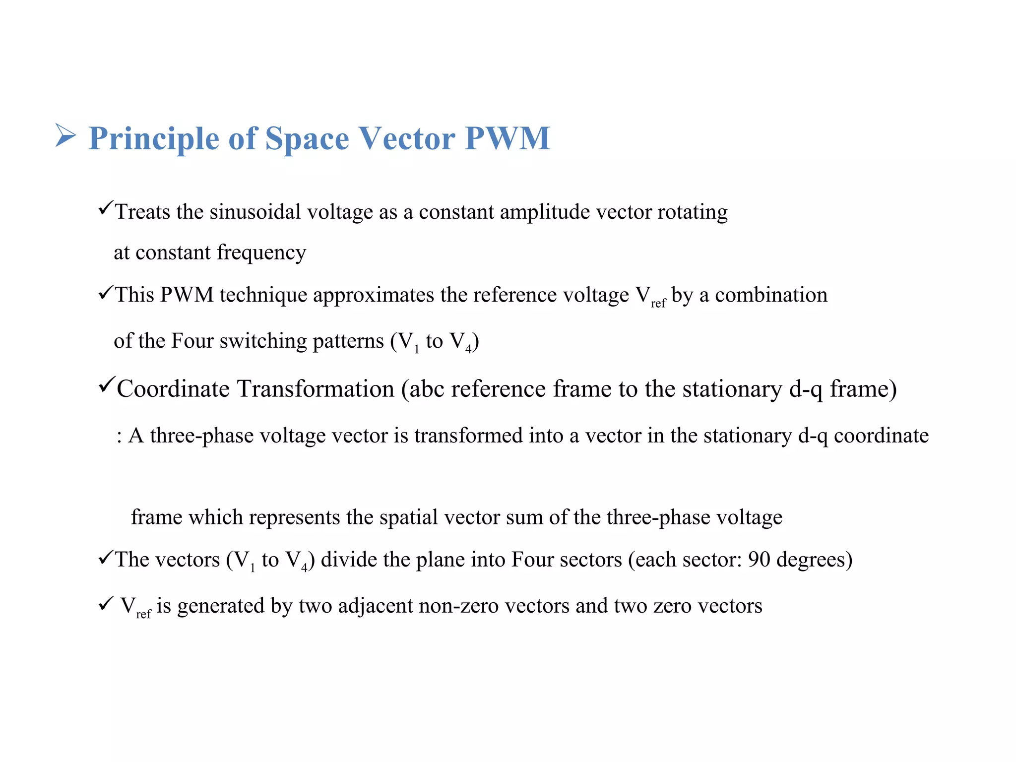
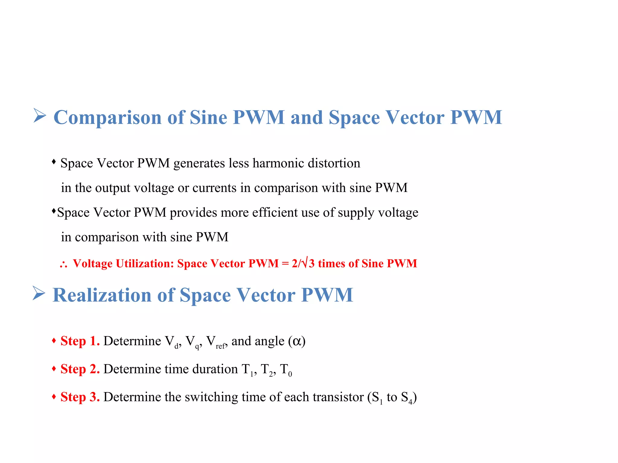
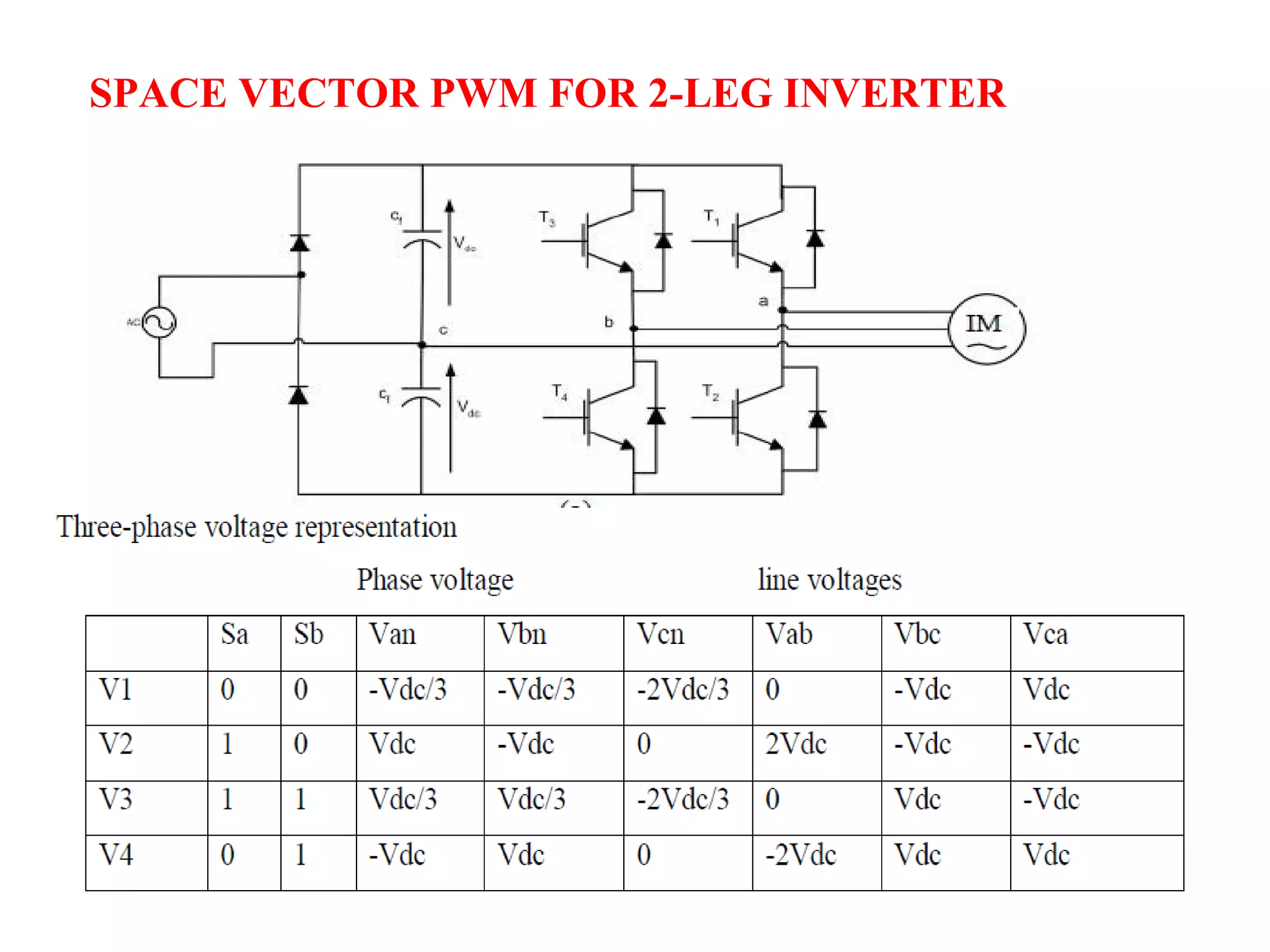
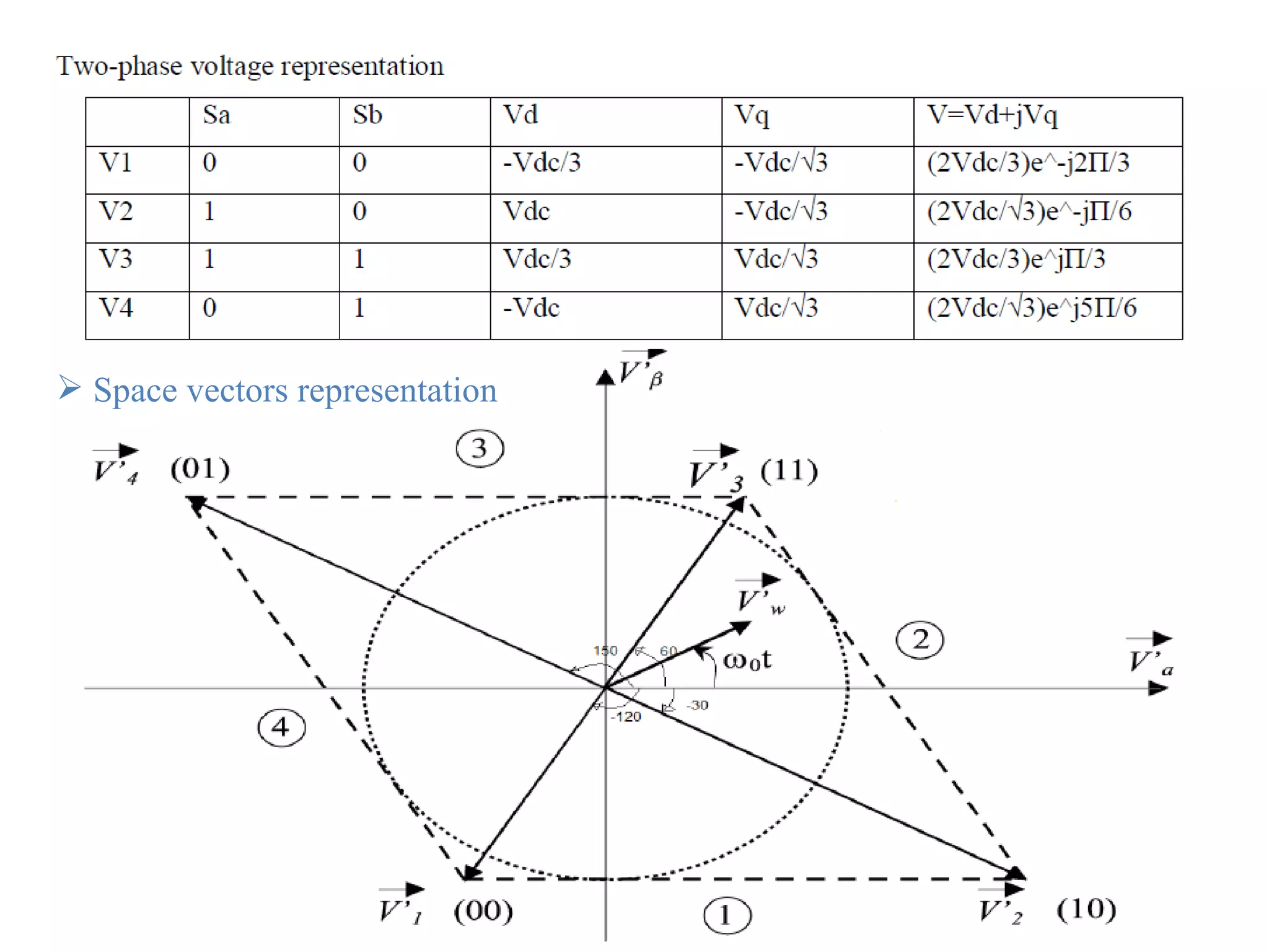
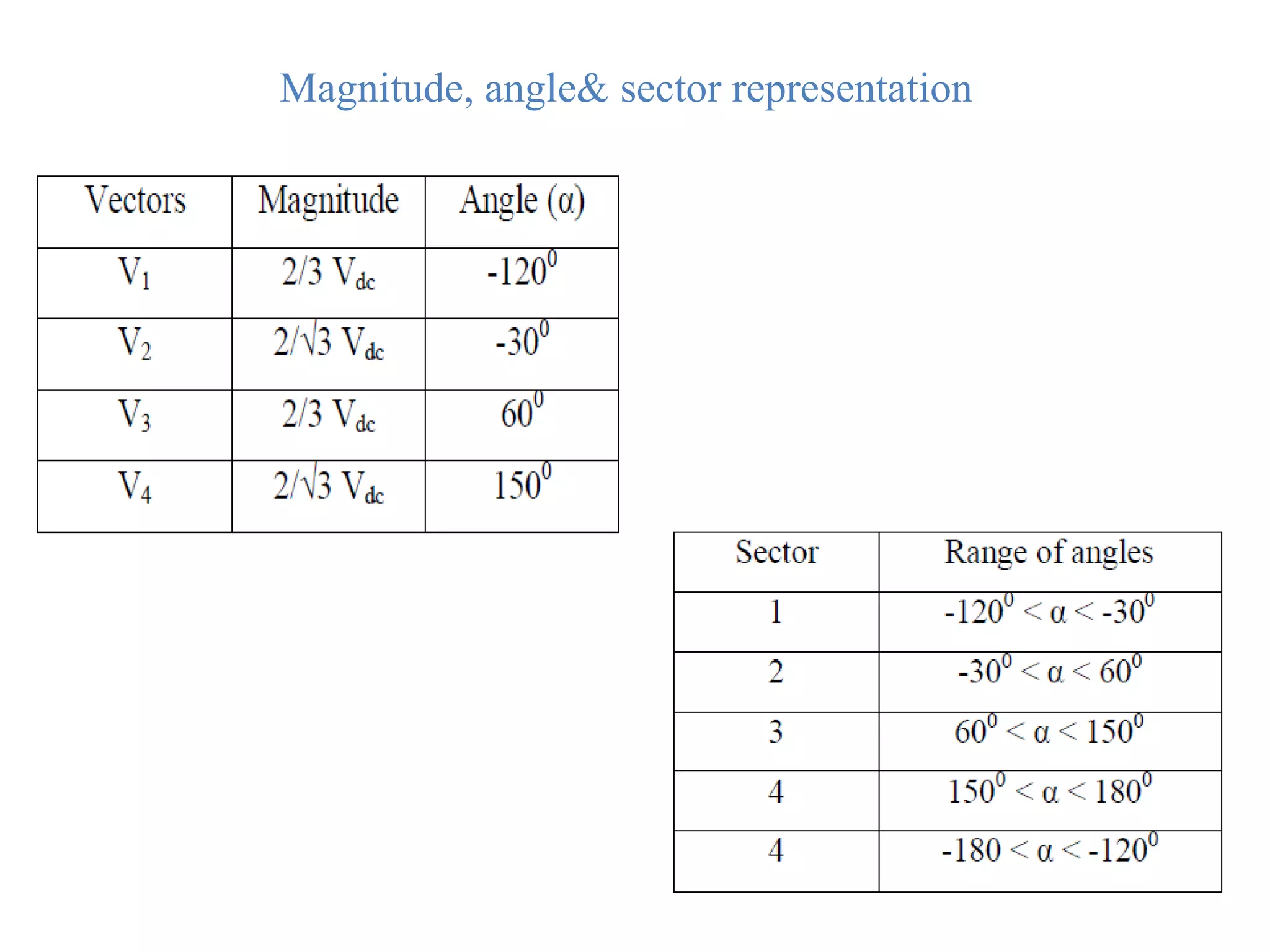
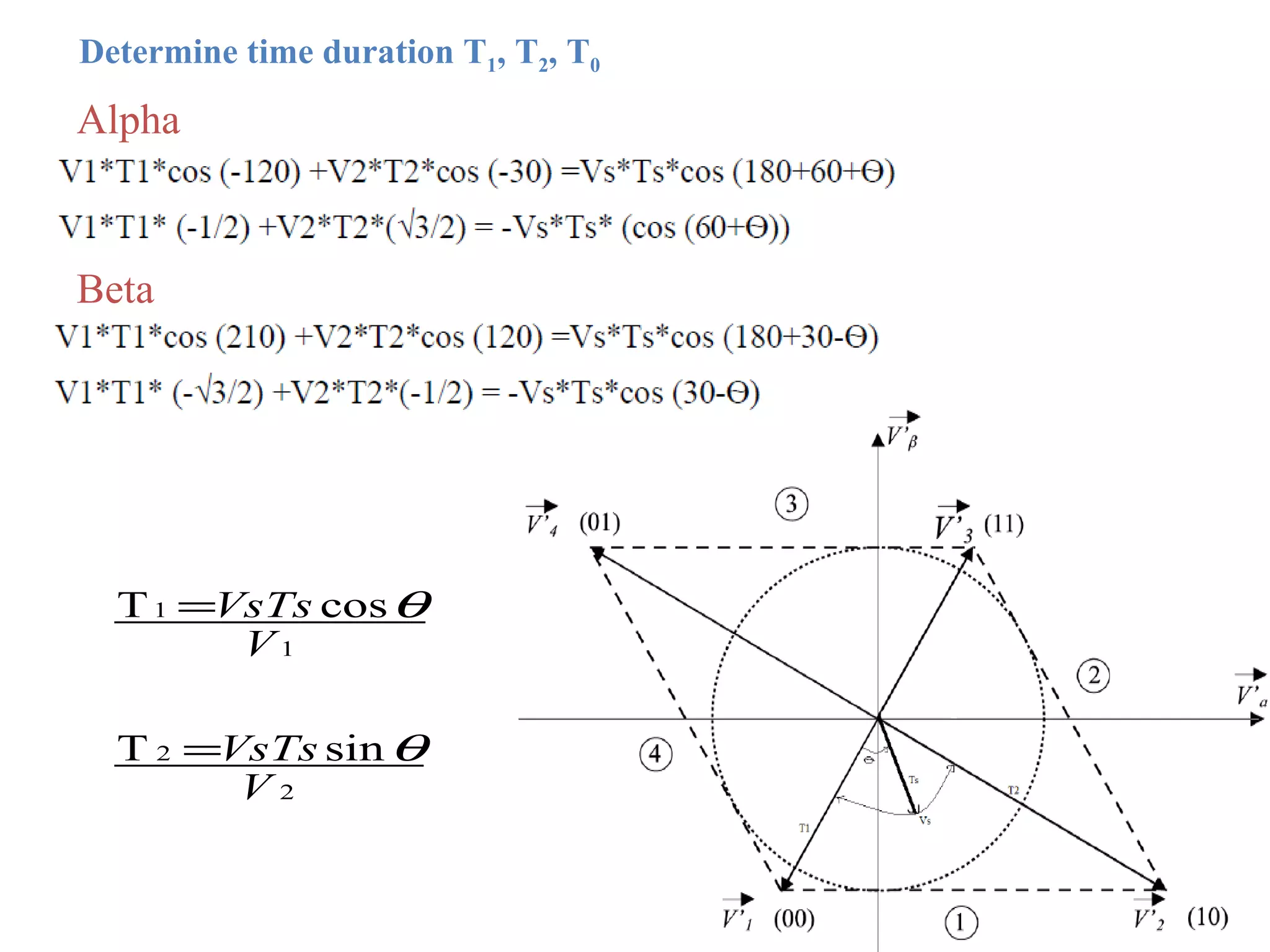
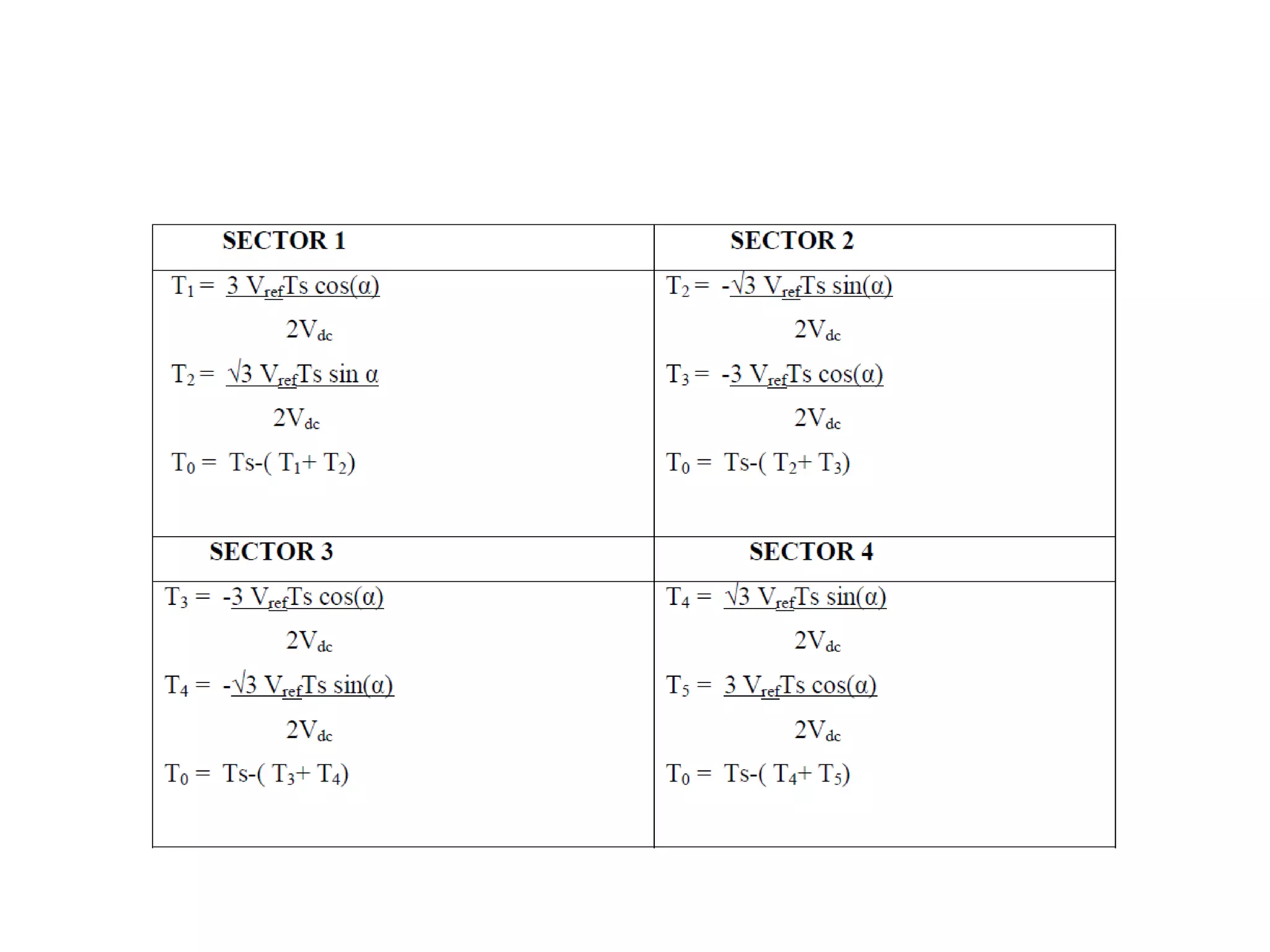
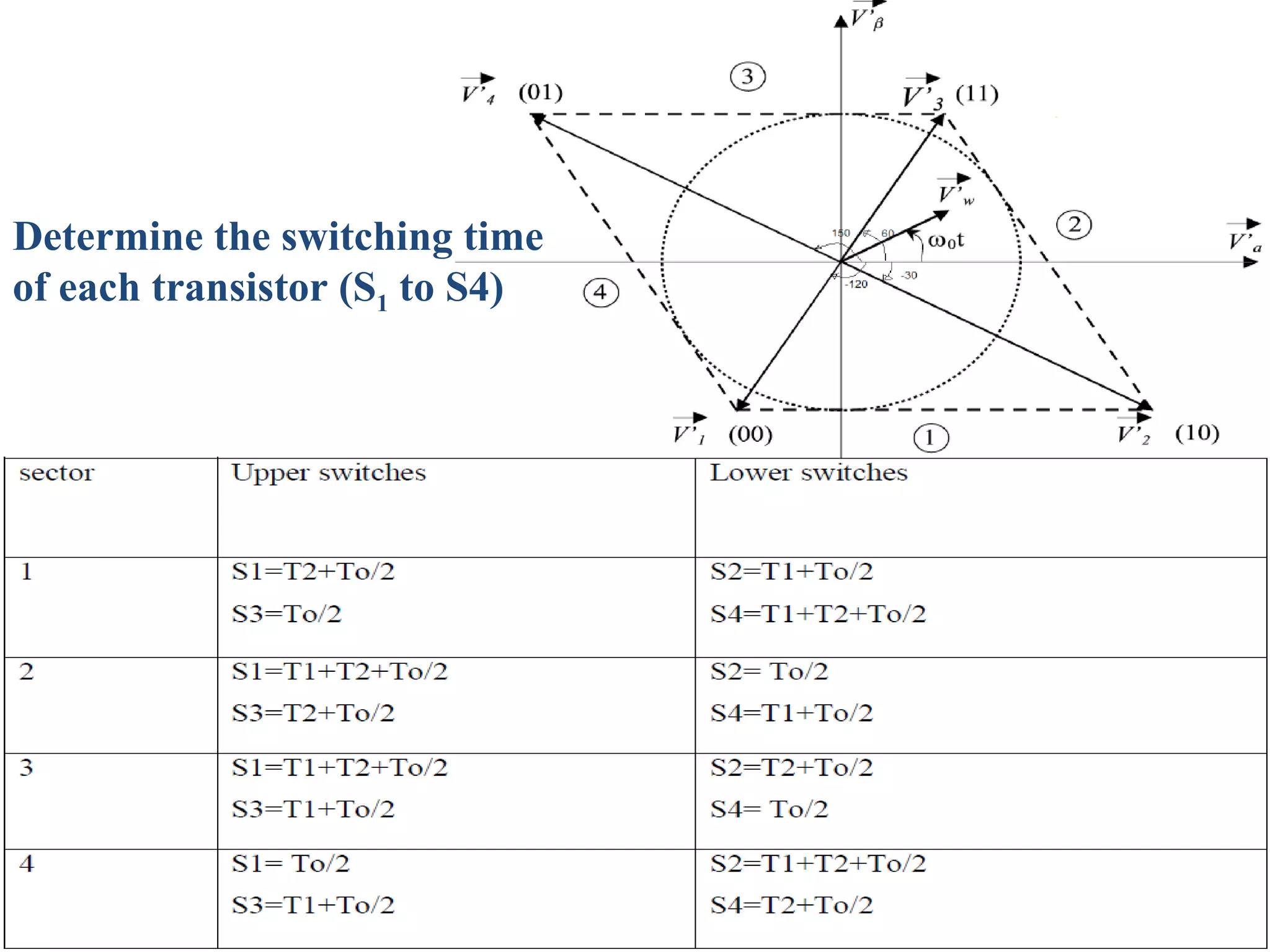
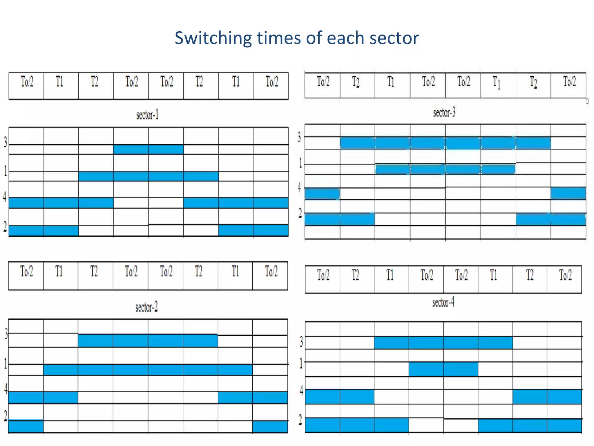
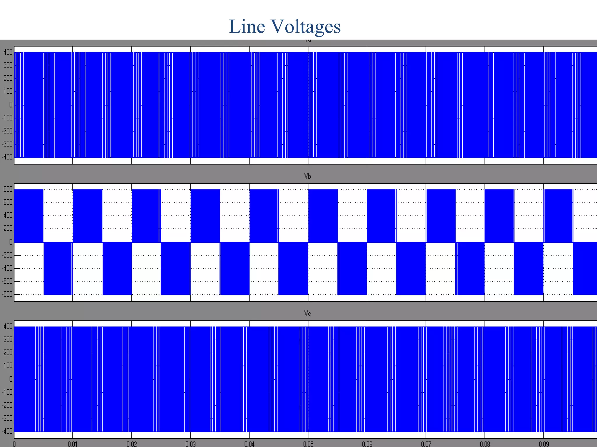
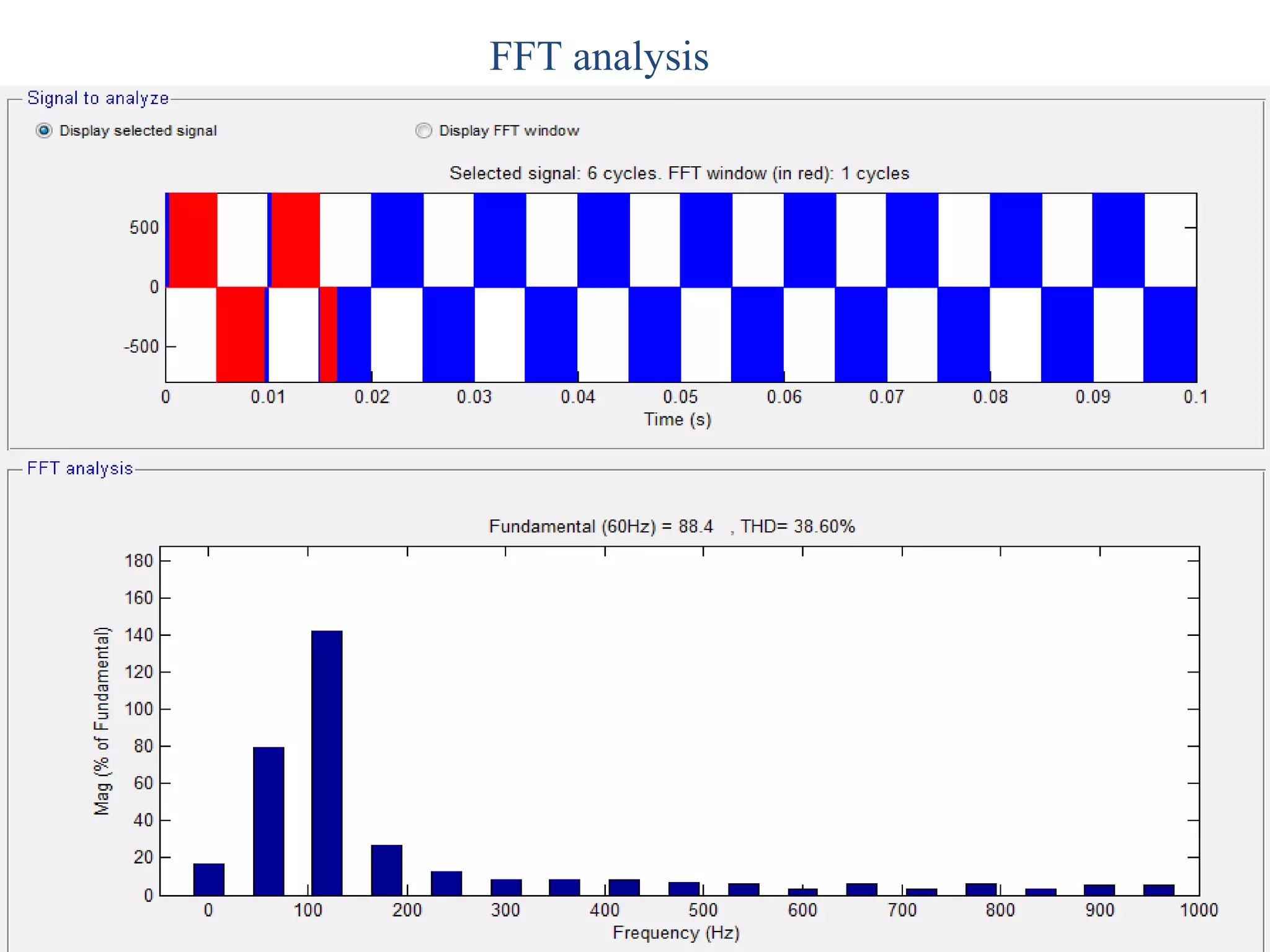
1. The document presents space vector modulation for two leg inverters. Space vector modulation treats the inverter as a single unit and provides better voltage utilization compared to sinusoidal pulse width modulation. 2. Space vector modulation represents the reference voltage as a combination of four switching vectors and determines the switching times of each transistor based on the location of the reference vector in the selected sector. 3. Simulation results show that space vector modulation generates less output voltage harmonics than sinusoidal pulse width modulation for two leg inverters.