The document discusses the performance improvement of a multi-level inverter fed vector-controlled induction motor drive, specifically focusing on low-speed operations. It highlights that the five-level inverter outperforms two-level and three-level inverters by significantly reducing torque ripple and improving speed response during transient conditions. The analysis indicates that employing multi-level inverters enhances the overall drive performance due to better handling of non-linearities caused by inverter and stator voltage drops.
![International Journal of Power Electronics and Drive System (IJPEDS)
Vol. 4, No. 1, March 2014 pp. 51~60
ISSN: 2088-8694 51
Journal homepage: http://iaesjournal.com/online/index.php/IJPEDS
Performance Improvement of Multi Level Inverter fed Vector
Controlled Induction Motor Drive for Low Speed Operations
K Satyanarayana*, B Anjaneyulu*, K Siva Prasad*
* Departement of Electrical and Electronics Engineering, Pragati Engineering College, Surampalem
Article Info ABSTRACT
Article history:
Received Oct 27, 2013
Revised Dec 2, 2013
Accepted Dec 26, 2013
In this paper, the analysis of space vector based multi level inverter (MLI)
fed vector controlled induction motor drive for a low speed operation is
presented. The performance of indirect field oriented controlled induction
motor drive (IMD) is poor with two-level inverter for low speed operations
(LSO). The reduction in performance and peak value of torque are mainly
due to the non-linearity caused by stator voltage drop and inverter. Hence the
performance factors of induction motor drive are analyzed with the multi
level inverters under different operating conditions. In this approach, the
steady state ripple content in the current and torque waveforms are reduced
and that to ripple content of torque is reduced from 0.15 to 0.05 under steady
state with five-level inverter. When there is a step change in the load torque,
the momentary decrease in speed with five-level inverter is less when
compared two and three-level inverters and the speed response reaches the
reference value very quickly with five-level inverter during steady state and
transient periods. So the overall performance of drive is improved with five-
level inverter when compared to two-level and three- level inverters under
low speed operations.
Keyword:
IFO
IMD
LSO
MLI
SVPWM
Copyright © 2014 Institute of Advanced Engineering and Science.
All rights reserved.
Corresponding Author:
K Satyanarayana
Departement of Electrical and Electronics Engineering,
Pragati Engineering College,
1-378, ADB Road, Surampalem, East Godavari District, Andhra Pradesh, India, 533437
Email: snkola@gmail.com
1. INTRODUCTION
Recent developments in power electronics and semiconductor technology have led improvements in
power electronic systems. Due to the advantages in power electronics, field oriented controlled induction
motor drives are popular in industrial applications in place of DC machines. In Indirect field oriented control
(FOC) the total rotor flux is aligned along the d-axis and the q-axis rotor flux is set to zero. Due to this
induction motor can be controlled like a separately excited DC motor as explained in [1]. But the
performance vector control under low speed operation is not satisfactory because of problems associated with
unbalances, drift etc studied in [2]-[3]. The concept of the low speed operation of sensor less vector control,
various strategies have been developed and studied in [4]. In all these strategies, nonlinearities introduced by
inverter and parameter variations are discussed in [5]. In order to reduce these problems and to obtain better
performance various observers are placed in the sensor less vector control. Due to this circuit complexity is
increased and the improvement in the performance is not satisfactory and explained in [6].
The concept of the multi-level pulse width modulation (PWM) converter, various modulation
strategies have been developed and studied in [7]-[8]. In all these strategies, space-vector modulation (SVM)
stands out because it offers significant flexibility to optimize switching waveforms and it is well suited for
implementation on a digital computer. However, regardless of its advantages, SVM for three-level inverters
is still mostly unexplored. A new simplified space vector pulse width modulation (SVPWM) method for](https://image.slidesharecdn.com/052dec13id4968ijpedsmlvcimdsn-171212151148/75/Performance-Improvement-of-Multi-Level-Inverter-fed-Vector-Controlled-Induction-Motor-Drive-for-Low-Speed-Operations-1-2048.jpg)
![ ISSN: 2088-8694
IJPEDS Vol. 4, No. 1, March 2014 : 51 – 60
52
three-level inverter is proposed [10]. The performance factors of indirect vector controlled induction motor
drive are proposed with two and three-level inverters at [13].
This paper presents the performance factors of induction motor drive are analyzed and compared
with the multi level inverters under different operating conditions at low speed (500 rpm) operations.
2 CONVENTIONAL FOC ALGORITHM :
Though the induction motor has a very simple construction, its mathematical model is complex due
to the coupling factor between a large number of variables and the non-linearities. The FOC offers a solution
to circumvent the need to solve high order equations and achieve an efficient control with high dynamic. The
FOC algorithm controls the components of the motor stator currents, represented by a vector, in a rotating
reference frame. In the FOC algorithm, the machine torque and rotor flux linkage are regulated by controlling
the stator current vector. The stator current vector is resolved into a torque producing component (
*
qsi ) and
flux producing component ( *
dsi ) in a rotating reference frame respectively. The flux component is oriented
along the rotor flux linkage vector, and the torque component is perpendicular to the flux component. This
decouples the torque control from the flux control. The electromagnetic torque expression for an induction
motor is given as
dsiqrqsidr
rL
mL
2
P
2
3
eT (1)
To achieve decoupling control, the entire rotor flux is aligned along d-axis and hence the q-axis flux
component will become zero. With this, the torque expression can be modified as given in (2).
qsidr
rL
mL
2
P
2
3
eT (2)
Hence, the total rotor flux can be given as in (3).
dsimLdrr (3)
From (3), it can be observed that the rotor flux is directly proportional to *
dsi and is maintained constant.
Hence, the torque linearly depends on *
qsi , and provides a torque response as fast as the *
qsi response. Then,
the slip frequency can be evaluated from (4) and added to the rotor speed to generate unit vectors.
*
qsi
rrL
rRmL
sl
(4)
3 SVPWM BASED MULTI LEVEL INVERTERS (EXISTING METHODS):
3.1 Two-level Inverter
The three-phase, two-level VSI has a simple structure and generates a low-frequency output voltage
with controllable amplitude and frequency by programming high-frequency gating pulses. For a 3-phase,
two-level VSI, there are eight possible voltage vectors, which can be represented as shown in Figure 1.
Among these voltage vectors, V1 to V6 vectors are known as active voltage vectors or active states and the
remaining two vectors are known as zero states or zero voltage vectors.
6...,1,2,krewhe3
)1k(j
edcV
3
2
kV
(5)
and dcV is dc link voltage.
The active voltage vectors can be represented as given in (5).](https://image.slidesharecdn.com/052dec13id4968ijpedsmlvcimdsn-171212151148/75/Performance-Improvement-of-Multi-Level-Inverter-fed-Vector-Controlled-Induction-Motor-Drive-for-Low-Speed-Operations-2-2048.jpg)
![IJPEDS ISSN: 2088-8694
Performance Improvement of Multi Level Inverter fed Vector Controlled Induction … (K. Satyanarayana)
53
The reference voltage space vector or sample, which is as shown in Figure 1 represents the
corresponding to the desired value of the fundamental components for the output phase voltages. In the space
vector approach this can be constructed in an average sense. refV is sampled at equal intervals of time, sT
referred to as sampling time period.
Figure 1. Possible voltage space vectors for VSI
Different voltage vectors that can be produced by the inverter are applied over different time
durations with in a sampling time period such that the average vector produced over the sampling time period
is equal to the sampled value of the refV , both in terms of magnitude and angle. It has been established that
the vectors to be used to generate any sample are the zero voltage vectors and the two active voltage vectors
forming the boundary of the sector in which the sample lies. As all six sectors are symmetrical, the discussion
is limited to the first sector only. For the required reference voltage vector, the active and zero voltage
vectors times can be calculated as in (6), (7) and (8).
sT)o60sin(iM
32
1T
(6)
T)sin(M
32
T si2
(7)
21sz TTTT (8)
where Mi is the modulation index and defined as in [11]. In the SVPWM algorithm, the total zero voltage
vector time is equally divided between V0 and V7 and distributed symmetrically at the start and end of the
each sampling time period. Thus, SVPWM uses 0127-7210 in sector-I, 0327-7230 in sector-II and so on.
3.2 Three-Level Inverter
The space vector diagram three-level inverter is shown in Figure 2 and all these voltage space
vectors can be grouped into four groups based on their magnitude namely, zero vector, small vectors,
medium vectors and large vectors. The zero voltage vector has two redundant states and small voltage
vectors have one redundant state. In conventional space vector PWM (CSVPWM) generation, the reference
voltage vector is sampled at regular time intervals and also the reference voltage vector is approximated by
time averaging the nearest three voltage vectors. Unlike two level inverters, in the case of three level
inverters, the zero vector is no longer common for all the regions. Figure 2 shows the representation of the
space voltage vectors for output voltage and the space vector diagram of all switching states, where the P, O,
N represent terminal voltage respectively, that is Vdc/2, 0, -Vdc/2. According to the magnitude of the voltage
Vref
V1 (100)
V2 (110)V3 (010)
V4 (011)
V5 (001) V6 (101)
V0 (000)
V7 (111)
I
II
III
IV
V
VI
q
d
T1
T2](https://image.slidesharecdn.com/052dec13id4968ijpedsmlvcimdsn-171212151148/75/Performance-Improvement-of-Multi-Level-Inverter-fed-Vector-Controlled-Induction-Motor-Drive-for-Low-Speed-Operations-3-2048.jpg)
![ ISSN: 2088-8694
IJPEDS Vol. 4, No. 1, March 2014 : 51 – 60
54
vectors, we divide them into four groups; zero voltage vector (V0), small voltage vectors (V1,V4, V7, V10,
V13, V16), middle voltage vectors (V3, V6, V9, V12, V15, V18) and large voltage vector (V2, V5, V8, V11,
V14, V17). The zero voltage vector (ZVV) has three switching states, small voltage vector (SVV) has two
switching states, the middle voltage vector (MVV) and large voltage vector (LVV) have only one switching
state and as explained in [11].
Figure 2. Space vectors of a three level inverter
The switching states of different sections of three-level inverter are shown in Table 1 and Table 2 which
shows the switching times of voltage vector in sector-I where VK
3
2
Table 1. Switching states of three-level inverter
Switching symbols
Switching conditions
Output voltage
S11 S12 S13 S14
P ON ON OFF OFF + Vdc/2
O OFF ON ON OFF 0
N OFF OFF ON ON -Vdc/2
Table 2. Switching times of three-level inverter
Region Ta Tb Tc
1 2KTs Sin(60- ) Ts [1-2K Sin( +60)] 2KTs Sin(60- )
2 2Ts [1-K Sin( +60)] 2KTs Sin Ts [2K Sin(60- )+1]
3 Ts [1-2K Sin ] Ts [2K Sin( +60)-1] Ts [2KSin( -60)+1]
4 Ts [2K Sin -1] 2KTs Sin(60- ) 2Ts [1-K Sin( +60)]
3.3 Five–Level Inverter
In a five-level inverter, Each leg of the inverter can have five possible switching states, P1, P2, O,
N1 or N2. When the top four witches Sx1, Sx2, Sx3 and Sx4 (x = a, b, c) are turned on, switching state is P2.
When the switches Sx2, Sx3, Sx4 and Sx5 are turned on switching state is P1. When the switches Sx3, Sx4,
Sx5 and Sx6 are turned on, the switching state is O. when the switches Sx4, Sx5, Sx6 and Sx7 are turned on,
the switching state is N1. When the switches Sx5, Sx6, Sx7 and Sx8 are turned on, the switching state is N2.
Figure 3 shows the space vector diagram for five-level inverter.
NPN OPN PPN
NPO
OPO
NON
ONP
NPP
PON
OPP
OON PNN
NOP PNO
NNP
PPP
OOO
NNN
POO
ONN
OOP
NNO
POP
ONO
PPO
OON
PNP](https://image.slidesharecdn.com/052dec13id4968ijpedsmlvcimdsn-171212151148/75/Performance-Improvement-of-Multi-Level-Inverter-fed-Vector-Controlled-Induction-Motor-Drive-for-Low-Speed-Operations-4-2048.jpg)
![IJPEDS ISSN: 2088-8694
Performance Improvement of Multi Level Inverter fed Vector Controlled Induction … (K. Satyanarayana)
55
Table 3. Switching states and terminal voltage of five-level inverter
States SX1 SX2 SX3 SX4 SX5 SX6 SX7 SX8 VX0
P2 1 1 1 1 0 0 0 0 2E
P1 0 1 1 1 1 0 0 0 E
0 0 0 1 1 1 1 0 0 0
N1 0 0 0 1 1 1 1 0 -E
N2 0 0 0 0 1 1 1 1 -2E
The output voltage space vector is identified by combination of switching states P2, P1, O, N1 or N2
of the three legs. For example, in the case of P2ON1, the output terminals a, b and c have the potentials 2E, 0,
and −E respectively. Since five kinds of switching states exist in each leg, three-level inverter has 53
= 125
switching states. The output voltage vector can take only 61 discrete positions in the diagram because some
switches states are redundant and create the same space vector. In Figure 4, it is also indicated an arbitrary
reference vector V∗ to be generated by the inverter and studied in [12].
Figure 3. Space Vector diagram of Five-level inverter
In Multilevel inverters the reference voltage vector can be reproduced in the average sense by
switching amongst the inverter states situated at the vertices, which are in closest proximity to it. The duty
cycles (ON time for each state) will be found by equating volt-seconds of reference voltage with nearest 3
states.
3V3d2V2d1V1dm (9)
Where d1, d2 and d3 are duty cycles of voltage vectors (states) (V1, V2 and V3) in inverter space
vector diagram nearer to the reference vector and m is the voltage reference vector. The values of m1 and m2
N2P2P1
P2N2O
N 1N1 P2
N 2N1 P1
N 2N1 P2
N 1OP2
N2 N1 P1
P2N2 P1
P 2N 1P1
P1N2O
P 2OP1
P2N2P1
O N2 O
P 1O P2
ON1 P1
N1 N2 O
O1O2 P2
N 1N2P2
N2 N1 O
N2N2 P2 N1N2 P2 ON2 P2 P1N2 P2 P2N2 P2
ON1 P2
N 1N2 P1
P2N1 P2
P1 N2 P1
P1N1P2
ON2P2
N2 OP2
OP2O
N1P1N1
N2 O N2
P2O N2P2P1 N1
P1
P2P2O
P1P1O
O N2
P1P2O
OP1N1
N1 O N2
N2P2N1 N1P2N1 OP2N1 P1P2N1 P2P2N1 P2P1N2
N2P1N2 N1P1N2 OP2N2 P1P1N2
N1P2O
N2P1 N1
N2P2O
P2 N2 OP2NP1
P1 N 1 O
P2OP2
P1 N 1 O
ON2 N1
P2P1P2
P1OP1
O N1O
N1N2 N1
P 2P1P2
OO P1
ON1O
N1N2 N2
OP1P2
N1O P1
N2N1 O
N1P1P2
N 2OP1
N2P2P2
P2N2 N2
P1
N11
P1N1N
P2P1O
P 2O
N1
ON1 N2
P2P1P1
P1P1O
OO N1
N1N1 N2
P1 P2P1
OP1O
N1O N1
N2N1 N1
OP1P1
N1P2P1
N2O N2
N2P2N2 N1P2N2 OP2N2 P2P2N2 P2P2N2
N1P2P1
N2P1O
P2N2 N2P2 N1 N
PN2 N2
P2OO
PN1 N
O1N2 N2
P2P1P1
P1OO
ON1 N1
N1N2 N2
P2P2P2
P1P1P1
OOO
N2N1 N1
N2N2 N2
P1P2P2
OP1P1
N1OO
N2N1 N1
N2P2P2 N1P2P2 OP2P2
N2P1P1 N2P1P1
N2OO](https://image.slidesharecdn.com/052dec13id4968ijpedsmlvcimdsn-171212151148/75/Performance-Improvement-of-Multi-Level-Inverter-fed-Vector-Controlled-Induction-Motor-Drive-for-Low-Speed-Operations-5-2048.jpg)
![ ISSN: 2088-8694
IJPEDS Vol. 4, No. 1, March 2014 : 51 – 60
56
for reference vector in each region can be calculated with Equation (9). The duty cycles of vertices of
reference voltage will be m1, m2 and [1-(m1+m2)]. For example, with reference to m3 (reference vector in
region 2), the reference vector can be synthesized by switching vectors V1, V2 and V3. It shall be important to
note that duty cycle for switching state V1 shall be length of the vector joining V3 and V1, whereas, m1 is the
projection of reference vector m3 from origin. As such, the corrected duty cycle for switching state V1 in
present case would be (m1-0.25). The length of vector joining V3 and V2 is m2. As such, corrected duty cycles
for switching states V1, V2 and V3 would be (m1-0.25), m2 and (0.75-m1-m2) respectively. The values of m1
and m2 are useful in identifying the region where reference vector is located, which is the major problem in
multilevel inverters. The conditions for identifying reference vector location in each region and the corrected
duty cycles for each of the level of inverter are shown in Table-3. Once the region is identified, the
appropriate switching sequence of a region can be identified. The ON time period for each state can be
calculated with duty cycles as in (10), (11) and (12).
TON for state1 = Ts x m1 (10)
TON for state2 = Ts x m2 (11)
TON for state3 = Ts x[1- (m1+m2)] (12)
4 MULTI LEVEL INVERTER FED IFO BASED INDUCTION MOTOR DRIVE (PROPOSED
METHOD):
In the vector controlled induction motor drive, the multi level inverter is supposed to drive the
induction motor so that the slip frequency can be changed according to the particular requirement. Assuming
the rotor speed is measured, and then the slip speed is derived in the feed-forward manner. For decoupling
control, it is desirable that the rotor flux is aligned onto the d-axis of the synchronously rotating reference
frame, then dsimLrdrand0qr . The block diagram of proposed vector controlled
induction motor drive is as shown in Fig. 4. This shows how the rotor flux linkage position can be obtained
by integrating the sum of rotor speed and actual speed. In the vector control scheme, to regulate r and
rotor speed to desired values are the two objectives. Apparently the stator voltages that are required to
generate the desired rotor flux linkage and rotor speed are not directly related to these variables. So the
alternative way is to regulate the rotor flux linkage and rotor speed through PI controllers and the outputs of
these two controllers give out the reference values for the q- and d-axis stator currents in synchronous
reference frame. Then the actual q- and d-axis stator currents are regulated to these two reference currents to
get the stator voltages. Then these two-phase voltages are converted into three-phase voltages and given to
the SVPWM block, which generates the gating pulses to the Multi Level Inverter.
Figure 4. Block diagram of proposed Multi level inverter fed IFO based induction motor drive
Sc
Sb
Sa
ib
I
ids
iqs
V*
qs
V*
ds
ids
iqs
iqs
*
ids
*
ω
ω
Slip & Angle
Calculation
Multi
Level
Inverter
3-ph
to
2-ph
Speed
controller
PI
2-ph
to
3-ph
S
V
P
W
M
Field weaken
control PI
IM
Va
Vb
Vc
Vdc](https://image.slidesharecdn.com/052dec13id4968ijpedsmlvcimdsn-171212151148/75/Performance-Improvement-of-Multi-Level-Inverter-fed-Vector-Controlled-Induction-Motor-Drive-for-Low-Speed-Operations-6-2048.jpg)
![IJPEDS ISSN: 2088-8694
Performance Improvement of Multi Level Inverter fed Vector Controlled Induction … (K. Satyanarayana)
59
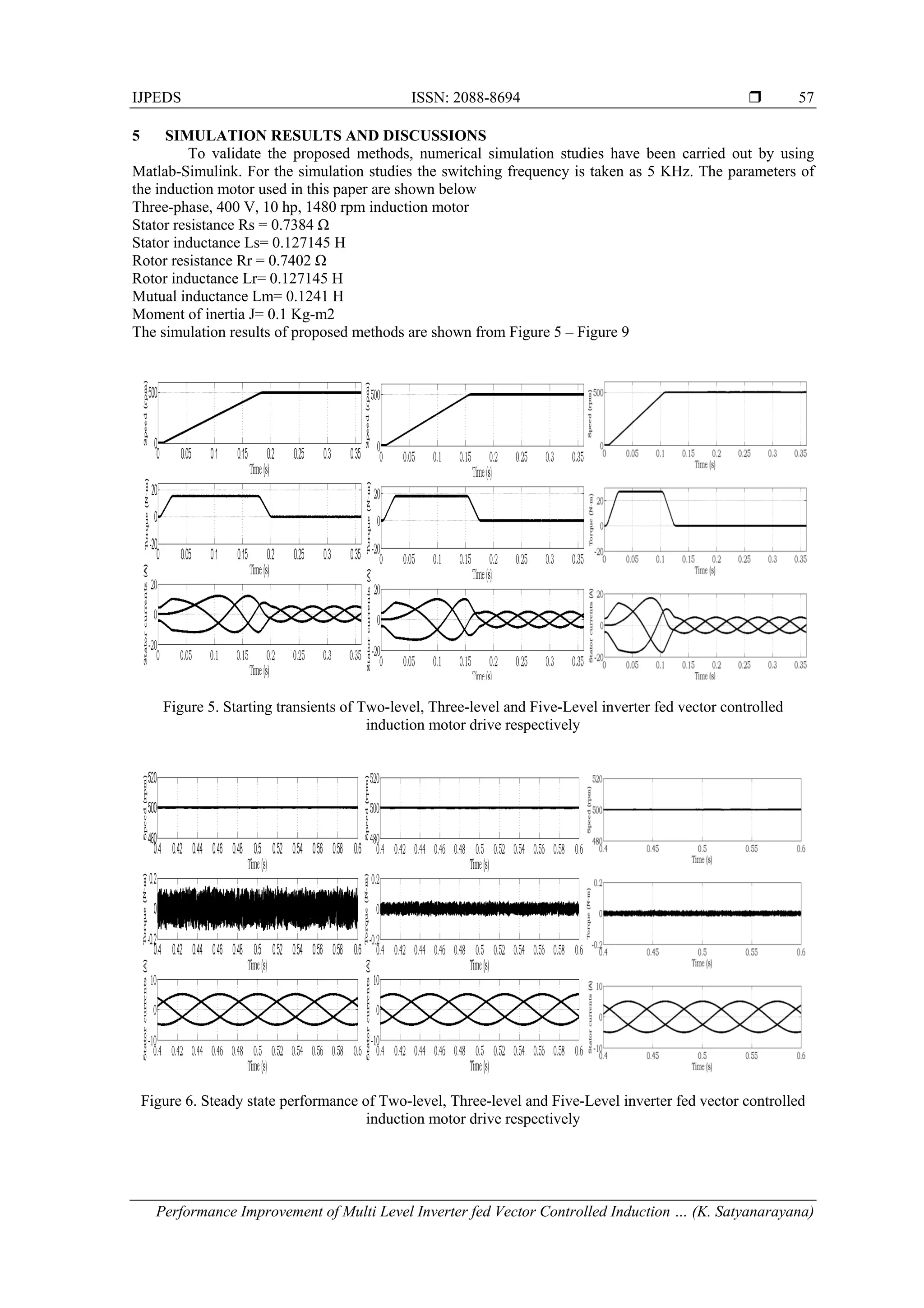
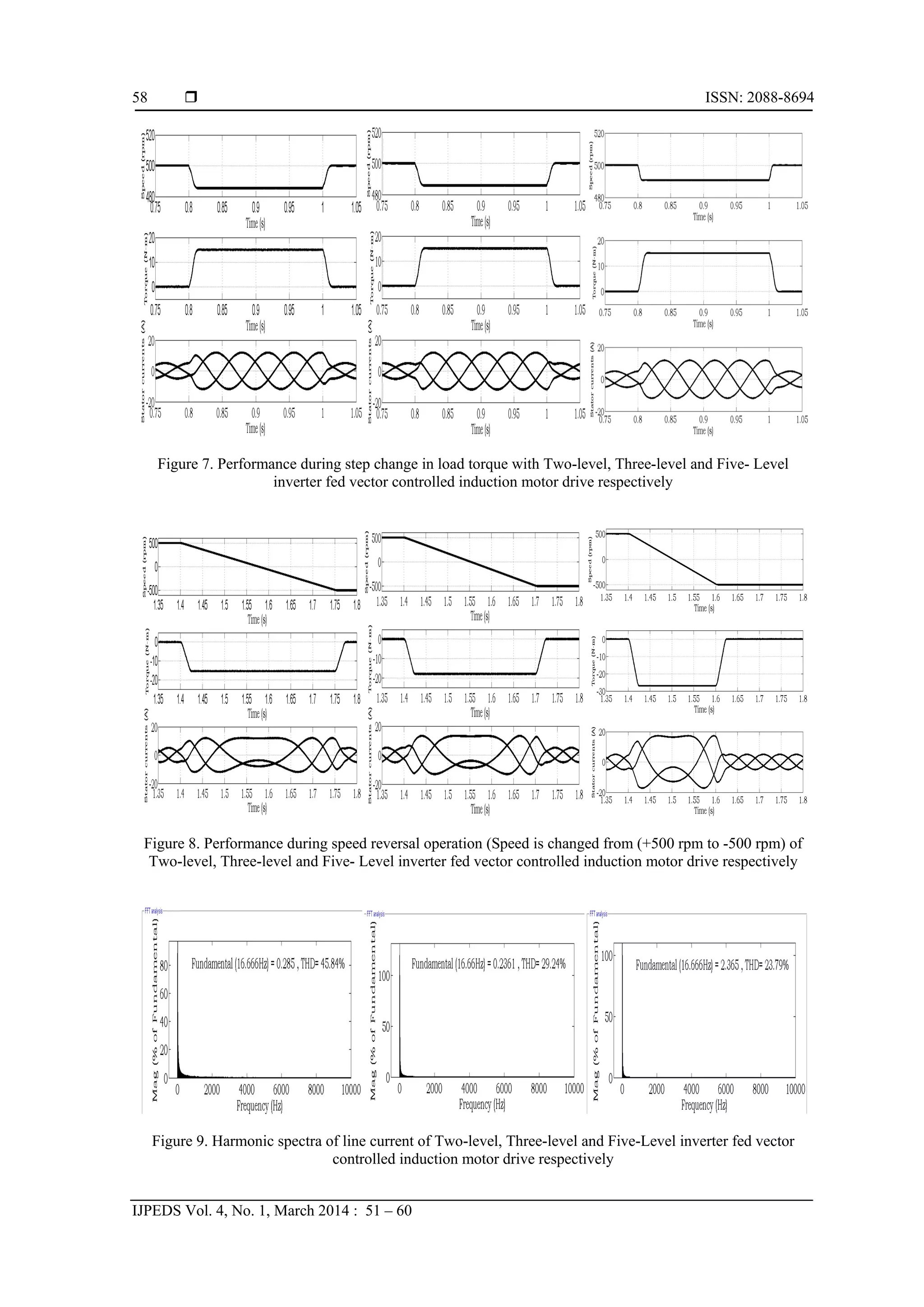
From the simulation results, the following observations are made. The starting transients are upto 0.18 secs,
0.16 secs and 0.12 secs in with two-level, three level and five-level inverters respectively. From the steady
state performance factors, It is observed that the torque ripple is drastically reduced from 0.15 to 0.05 with
five-level inverter. The response during change in load torque command (the load torque of 15 N-m is
applied at 0.8 sec and removed at 1 sec) and the momentary decrease in speed with five-level inverter is less
when compared with two-level and three-level inverters. The speed reversal response (from +500 rpm to -500
rpm) is also better with five-level inverter. Finally the performance of five-level inverter fed drive provides
better performance based on harmonic spectra of line current (low THD) when compared to the two-level and
three-level inverters.
6 CONCLUSION
The indirect vector controlled induction motor drive performance with multi level inverters under
low speed operations is presented. It is observed that the performance of the drive is improved with the five-
level inverter when compared to two and three-level inverters. The steady state ripple content in the current
and torque waveforms are reduced and that to ripple content of torque is reduced from 0.15 to 0.05 under
steady state with five-level inverter. When there is a step change in the load torque, the momentary decrease
in speed with five-level inverter is less when compared two and three-level inverters. The speed response
reaches the reference value very quickly with five-level inverter during steady state and transient periods. So
the overall performance of drive is improved with five-level inverter when compared to other inverters under
low speed operations.
REFERENCES
[1] F Blaschke. “The principle of field orientation as applied to the new transvector closed loop control system for
rotating-field machines". Siemens Review. 1972: 217-220.
[2] Joachim Holtz. “Pulsewidth modulation – A survey”. IEEE Trans. Ind. Electron. 1992; 39(5): 410-420.
[3] Joachim Holtz and Juntao Quan. “Sensor less vector control of induction motors at very low speed using a nonlinear
inverter model and parameter identification”. IEEE Trans. Industry Applications. 2002.
[4] Cesar Silva and Ricardo Araya. “Sensor less vector control of induction machine with low speed capability using
mras with drift and inverter nonlinearities compensation”. EUROCON Conference. 2007.
[5] Shady M Gadoue, Damian Giaouris and John W Finch. “Performance evaluation of a sensor less induction motor
drive at very low and zero speed using a MRAS speed observer”. 3rd
international Industrial and Information
Systems Conference.. 200.
[6] Tetsuya Fukumoto, Yousuke kato, Kazuya Kurita, and Yoichi Hayashi. “Performance improvement of Induction
Motor Speed Sensor-Less Vector Control System Using an Adaptive Observer with an Estimated Flux Feedback in
Low-Speed Range”. Electrical Engineering in Japan. 2009; 169: 329-339.
[7] N Celanovic and D Boroyevich, “A fast space-vector modulation algorithm for multilevel three phase converters”.
IEEE Trans. Trans. Industry Applications. 2001; 37: 637-641.
[8] MM Prats, R Portillo, JM Carrasco, and LG Franquelo. “New fast space-vector modulation for multilevel converters
based on geometrical considerations”. 28th Annual Industrial Electronics Society conference. 2002; 4: 3134–3138.
[9] Djaafer Lalili, Nabil Lourci, El madjid Berkouk, Fares Boudjema and J Petzold. “Simplified Space Vector Pulse
width Modulation Algorithm for Three Level Inverter with Neutral Point Potential Control”. Research Journal
of Applied Sciences. 1 (1-14):19-25, Medwell Online (2006).
[10] Aneesh Mohamed, AS Anish Gopinath, and MR Baiju. “A simple space vector PWM generation scheme for any
general n-level inverter”. IEEE Trans. Industrial Electronics. 2009; 56: 1649-1656.
[11] P Satish Kumar, J Amarnath, SVL Narasimham. “An Improved SVPWM Algorithm for Diode Clamping Inverter”.
Journal of Current Science. 2008; 12(2): 831-837.
[12] P Satish Kumar, J Amarnath, SVL Narasimham. “A Qualitative Space Vector PWM Algorithm for a Five-level
Neutral Point Clamped Inverter”. The International Congress for Global Science and Technology-Automatic
Control and System Engineering Journal. 2009; 9(I): 43-50.
[13] G Durgasukumar and MK Pathak. “Indirect Vector Control Induction Motor Drive Performance under Low Speed”.
J Electrical Systems. 2012; 8-3: 338-347.](https://image.slidesharecdn.com/052dec13id4968ijpedsmlvcimdsn-171212151148/75/Performance-Improvement-of-Multi-Level-Inverter-fed-Vector-Controlled-Induction-Motor-Drive-for-Low-Speed-Operations-9-2048.jpg)


![3.[14 28]space vector based dual zero-vector random centered distribution pwm...](https://cdn.slidesharecdn.com/ss_thumbnails/3-14-28spacevectorbaseddualzero-vectorrandomcentereddistributionpwmalgorithmfordirecttorquecontrolofinductionmotordriveforreducedacousticalnoise-111203185000-phpapp02-thumbnail.jpg?width=640&height=640&fit=bounds)