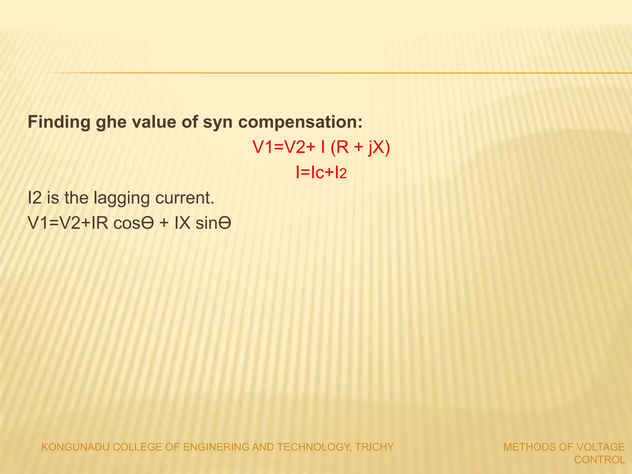
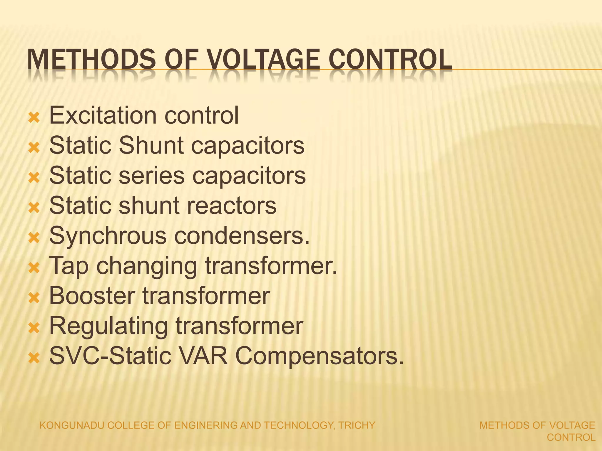
METHODS OF VOLTAGE CONTROL
 Excitation control
 Static Shunt capacitors
 Static series capacitors
 Static shunt reactors
 Synchrous condensers.
 Tap changing transformer.
 Booster transformer
 Regulating transformer
 SVC-Static VAR Compensators.
KONGUNADU COLLEGE OF ENGINERING AND TECHNOLOGY, TRICHY METHODS OF VOLTAGE
CONTROL
SHUNT CAPACITORS:
 It supplies reactive power for both Transmission and distribution side.
 Connected to bus bar or tertiary winding of main TF.
 It can controlled by switching.
 Supplies reactive power to lead the current from voltage.
 Power factor improved.
 VAR α V2
Voltage rise by Shunt C:
Volt drop without Shunt C:
⌂V = (P2R +Q2X) / V
Volt drop with Shunt C:
⌂V’ = [P2R + (Q2-Qc)X ]/ V
Capacitor voltage rise : ⌂Vc = QcX / V
KONGUNADU COLLEGE OF ENGINERING AND TECHNOLOGY, TRICHY METHODS OF VOLTAGE
CONTROL
 It is connected series in the line to compensate the inductive reactance
of line.
 Increases maximum power transfer, reduces reactive power loss.
 Under fault condition voltage across the C rises. So fault current also
increases 4 times of rated current.
 Zinc oxide varistor is used to bypass the current and give to the load.( it
is for particular level of currents)
 Drainage reactance used to prevent the current flow through the breaker
and bypass to the varistors for particular limits.
 Exceeds the current limit means, reactor allows the current, the given to
breaker. It disconnect the C from fault current.
KONGUNADU COLLEGE OF ENGINERING AND TECHNOLOGY, TRICHY METHODS OF VOLTAGE
CONTROL
SERIES CAPACITORS
 V= IR cosØr + IXLsinØr –Ixc sinØr
= IR cosØr + I(XL-Xc)sinØr
The voltage boost producesd by series capacitor
is
⌂V= I Xc sinØr
Improve the volt regulations in distribution feeders.
Improve system stability.
KONGUNADU COLLEGE OF ENGINERING AND TECHNOLOGY, TRICHY METHODS OF VOLTAGE
CONTROL
SHUNT REACTORS
 Used to reduce the voltage rise in open circuit with light loads.
 It absorbs the reactive power. Used in longer EHV lines.
 It is connected by switching operation to the lines.
 But in heavy loads some reactors are disconnected by switching and
breakers.
 Used to maintain nominal voltage under light load conditions.
 Some reactors are permanently connected to the lines.
 It can connected to lines or tertiary winding of TF.
 Tap changing Reactors also used to connect the reactor w.r.t loads.
SYNCHRONOUS CONDENSERS
 Synchronous motor running over excited means supply reactive power.
 Synchronous motor running under excited means absorb reactive
power.
 The running of synchronous motor is controlled by AVR in field of Syn
motor.
 It is also called as active compensators.
 Used in HVDC lines and voltage controls with upset conditions with Volt
regulators.
 It is connected to the tertiary wing of TF.
 It can operate as shunt C for over excited condition (Eg cosα > V)
 It can operate as shunt inductor for under excited condition (Eg
cosα < V)
KONGUNADU COLLEGE OF ENGINERING AND TECHNOLOGY, TRICHY METHODS OF VOLTAGE
CONTROL
Finding ghe value of syn compensation:
V1=V2+ I (R + jX)
I=Ic+I2
I2 is the lagging current.
V1=V2+IR cosϴ + IX sinϴ
KONGUNADU COLLEGE OF ENGINERING AND TECHNOLOGY, TRICHY METHODS OF VOLTAGE
CONTROL
REFERENCES:
 Jeraldin Ahila M., “Power system operation and control”, Lakshmi
Publications, 2015.
 Kundur P., ‘Power System Stability and Control, Tata McGraw Hill Education
Pvt. Ltd., New Delhi,10th reprint, 2010.
 R3. Hadi Saadat, ‘Power System Analysis’, Tata McGraw Hill Education Pvt.
Ltd., New Delhi, 21st reprint, 2010.
 R4. Ramanathan V., “Power System Operation and Control,” Charulatha
Publications, 2015.
 R5. Gross C.A., “Power System Analysis,” Wiley India, 2011.
 Google and Wikipedia.
KONGUNADU COLLEGE OF ENGINERING AND TECHNOLOGY, TRICHY METHODS OF VOLTAGE
CONTROL

Methods of voltage control

  • 1.
    METHODS OF VOLTAGECONTROL  Excitation control  Static Shunt capacitors  Static series capacitors  Static shunt reactors  Synchrous condensers.  Tap changing transformer.  Booster transformer  Regulating transformer  SVC-Static VAR Compensators. KONGUNADU COLLEGE OF ENGINERING AND TECHNOLOGY, TRICHY METHODS OF VOLTAGE CONTROL
  • 2.
    SHUNT CAPACITORS:  Itsupplies reactive power for both Transmission and distribution side.  Connected to bus bar or tertiary winding of main TF.  It can controlled by switching.  Supplies reactive power to lead the current from voltage.  Power factor improved.  VAR α V2 Voltage rise by Shunt C: Volt drop without Shunt C: ⌂V = (P2R +Q2X) / V Volt drop with Shunt C: ⌂V’ = [P2R + (Q2-Qc)X ]/ V Capacitor voltage rise : ⌂Vc = QcX / V KONGUNADU COLLEGE OF ENGINERING AND TECHNOLOGY, TRICHY METHODS OF VOLTAGE CONTROL
  • 3.
     It isconnected series in the line to compensate the inductive reactance of line.  Increases maximum power transfer, reduces reactive power loss.  Under fault condition voltage across the C rises. So fault current also increases 4 times of rated current.  Zinc oxide varistor is used to bypass the current and give to the load.( it is for particular level of currents)  Drainage reactance used to prevent the current flow through the breaker and bypass to the varistors for particular limits.  Exceeds the current limit means, reactor allows the current, the given to breaker. It disconnect the C from fault current. KONGUNADU COLLEGE OF ENGINERING AND TECHNOLOGY, TRICHY METHODS OF VOLTAGE CONTROL SERIES CAPACITORS
  • 4.
     V= IRcosØr + IXLsinØr –Ixc sinØr = IR cosØr + I(XL-Xc)sinØr The voltage boost producesd by series capacitor is ⌂V= I Xc sinØr Improve the volt regulations in distribution feeders. Improve system stability. KONGUNADU COLLEGE OF ENGINERING AND TECHNOLOGY, TRICHY METHODS OF VOLTAGE CONTROL
  • 5.
    SHUNT REACTORS  Usedto reduce the voltage rise in open circuit with light loads.  It absorbs the reactive power. Used in longer EHV lines.  It is connected by switching operation to the lines.  But in heavy loads some reactors are disconnected by switching and breakers.  Used to maintain nominal voltage under light load conditions.  Some reactors are permanently connected to the lines.  It can connected to lines or tertiary winding of TF.  Tap changing Reactors also used to connect the reactor w.r.t loads.
  • 6.
    SYNCHRONOUS CONDENSERS  Synchronousmotor running over excited means supply reactive power.  Synchronous motor running under excited means absorb reactive power.  The running of synchronous motor is controlled by AVR in field of Syn motor.  It is also called as active compensators.  Used in HVDC lines and voltage controls with upset conditions with Volt regulators.  It is connected to the tertiary wing of TF.  It can operate as shunt C for over excited condition (Eg cosα > V)  It can operate as shunt inductor for under excited condition (Eg cosα < V) KONGUNADU COLLEGE OF ENGINERING AND TECHNOLOGY, TRICHY METHODS OF VOLTAGE CONTROL
  • 7.
    Finding ghe valueof syn compensation: V1=V2+ I (R + jX) I=Ic+I2 I2 is the lagging current. V1=V2+IR cosϴ + IX sinϴ KONGUNADU COLLEGE OF ENGINERING AND TECHNOLOGY, TRICHY METHODS OF VOLTAGE CONTROL
  • 8.
    REFERENCES:  Jeraldin AhilaM., “Power system operation and control”, Lakshmi Publications, 2015.  Kundur P., ‘Power System Stability and Control, Tata McGraw Hill Education Pvt. Ltd., New Delhi,10th reprint, 2010.  R3. Hadi Saadat, ‘Power System Analysis’, Tata McGraw Hill Education Pvt. Ltd., New Delhi, 21st reprint, 2010.  R4. Ramanathan V., “Power System Operation and Control,” Charulatha Publications, 2015.  R5. Gross C.A., “Power System Analysis,” Wiley India, 2011.  Google and Wikipedia. KONGUNADU COLLEGE OF ENGINERING AND TECHNOLOGY, TRICHY METHODS OF VOLTAGE CONTROL