Download to read offline
![IJRET: International Journal of Research in Engineering and Technology eISSN: 2319-1163 | pISSN: 2321-7308
__________________________________________________________________________________________
Volume: 02 Issue: 11 | Nov-2013, Available @ http://www.ijret.org 448
IMPLEMENTATION OF dSPACE CONTROLLED DPWM BASED
INDUCTION MOTOR DRIVE
J.Jona1
, Y.Chintu Sagar2
, K. Sri Gowri3
, G.Kumaraswamy4
1, 2
PG Student, 3
Professor, 4
Assistant Professor, Electrical and Electronics, RGMCET NANDYAL, A.P, India
jona_jana@yahoo.co.in, chintu215@gmail.com, gowrivasu.3@gmail.com, kumar1718@gmail.com
Abstract
The paper presents dSPACE controlled Induction motor drive fed through Discontinuous pulse width modulation (DPWM) algorithm
based voltage source inverter. Two important performance measuring factors harmonic distortion in line current and dc bus
utilization of the inverter can be improved with Discontinuous PWM approach in comparison with the popular conventional space
vector (CSVPWM) approach; the paper contemplates on the implementation of DPWM algorithm for pulse generation which in turn
are fed to intelligent power module that feeds the motor drive through DS1104 PPC603e / 250 MHz control desk. The results conclude
the successful implementation of dSPACE Controlled induction motor drive. To validate the proposed work, numerical simulation
including the experimental results is presented.
Keywords:-DPWM, dSPACE, RTI
-----------------------------------------------------------------------***----------------------------------------------------------------------
1. INTRODUCTION
With the inventions of fast switching power semiconductor
devices and motor control algorithms, emerging interest
instituted among researchers in the area of PWM techniques.
During the past decade several PWM algorithms have been
studied extensively. Various PWM methods have been
developed to achieve wide modulation range, less switching
loss, improved total harmonic distortion (THD) with ease in
digital implementation with less computation burden on the
controller. A large variety of algorithms for PWM exist, and a
survey of these was done in [1]. There are two popular
approaches for the implementation of PWM algorithms,
namely triangular comparison (TC) approach and space vector
(SV) approach. For a long period, TC approach based PWM
methods were widely used in most applications. The earliest
modulation signals for TC approach are sinusoidal. But, the
addition of the zero sequence signals to the sinusoidal signals
results in several non-sinusoidal signals. Compared with
sinusoidal PWM (SPWM) algorithm, non-sinusoidal PWM
algorithms can extend the linear modulation range for line-to-
line voltages. Different zero-sequence signals lead to different
non sinusoidal PWM modulators [2]. In this paper pulse
generation through dSPACE control desk is done for DPWM
algorithm, which in turn generates the required ac voltage by
means of intelligent inverter module (PEC16DSM01). The
performance of the motor is tested at different modulation
indices ranging from low, medium to high. Simulation and
experimental results of pulse pattern for a-phase, modulating
waves of phase a, b are also presented.
With the development of digital signal processors, SVPWM
has become one of the most popular PWM methods for three-
phase inverters [3]-[4]. It uses the space vector approach to
compute the duty cycle of the switches. The main features of
this PWM algorithm are easy digital implementation and wide
linear modulation range for output line-to-line voltages. The
equivalence between TC and SV approaches were elaborated
in [5] and concluded that SV approach offers more degrees of
freedom compared to TC approach.
While, SVPWM gives superior performance, switching losses
in the inverter are more as it generates continuous pulses
(modulating signal). Hence, to reduce the switching losses of
the inverter, discontinuous PWM (DPWM) methods are
considered. The generation of these DPWM algorithms [6]-[8]
can also be considered. However, this paper presents the
results of CSVPWM along with few Discontinuous PWM
algorithms for induction motor using the conventional notion
of sector selection.
2. CONVENTIONAL SVPWM ALGORITHM
The main purpose of the voltage source inverter (VSI) is to
generate a three-phase voltage with controllable amplitude,
and frequency. A conventional 2-level, 3-phase VSI feeding a
three-phase induction motor is shown in Fig 1.
From Fig.1, it can be observed that the two switching devices
on the same leg cannot be turned on and cannot be turned off
at the same time, as this condition will result in short
circuit/open circuit to the connected phase. Thus the nature of
the two switches on the same leg is complementary. The](https://image.slidesharecdn.com/implementationofdspacecontrolleddpwmbased-160805140503/85/Implementation-of-d-space-controlled-dpwm-based-1-320.jpg)
![IJRET: International Journal of Research in Engineering and Technology eISSN: 2319-1163 | pISSN: 2321-7308
__________________________________________________________________________________________
Volume: 02 Issue: 11 | Nov-2013, Available @ http://www.ijret.org 448
IMPLEMENTATION OF dSPACE CONTROLLED DPWM BASED
INDUCTION MOTOR DRIVE
J.Jona1
, Y.Chintu Sagar2
, K. Sri Gowri3
, G.Kumaraswamy4
1, 2
PG Student, 3
Professor, 4
Assistant Professor, Electrical and Electronics, RGMCET NANDYAL, A.P, India
jona_jana@yahoo.co.in, chintu215@gmail.com, gowrivasu.3@gmail.com, kumar1718@gmail.com
Abstract
The paper presents dSPACE controlled Induction motor drive fed through Discontinuous pulse width modulation (DPWM) algorithm
based voltage source inverter. Two important performance measuring factors harmonic distortion in line current and dc bus
utilization of the inverter can be improved with Discontinuous PWM approach in comparison with the popular conventional space
vector (CSVPWM) approach; the paper contemplates on the implementation of DPWM algorithm for pulse generation which in turn
are fed to intelligent power module that feeds the motor drive through DS1104 PPC603e / 250 MHz control desk. The results conclude
the successful implementation of dSPACE Controlled induction motor drive. To validate the proposed work, numerical simulation
including the experimental results is presented.
Keywords:-DPWM, dSPACE, RTI
-----------------------------------------------------------------------***----------------------------------------------------------------------
1. INTRODUCTION
With the inventions of fast switching power semiconductor
devices and motor control algorithms, emerging interest
instituted among researchers in the area of PWM techniques.
During the past decade several PWM algorithms have been
studied extensively. Various PWM methods have been
developed to achieve wide modulation range, less switching
loss, improved total harmonic distortion (THD) with ease in
digital implementation with less computation burden on the
controller. A large variety of algorithms for PWM exist, and a
survey of these was done in [1]. There are two popular
approaches for the implementation of PWM algorithms,
namely triangular comparison (TC) approach and space vector
(SV) approach. For a long period, TC approach based PWM
methods were widely used in most applications. The earliest
modulation signals for TC approach are sinusoidal. But, the
addition of the zero sequence signals to the sinusoidal signals
results in several non-sinusoidal signals. Compared with
sinusoidal PWM (SPWM) algorithm, non-sinusoidal PWM
algorithms can extend the linear modulation range for line-to-
line voltages. Different zero-sequence signals lead to different
non sinusoidal PWM modulators [2]. In this paper pulse
generation through dSPACE control desk is done for DPWM
algorithm, which in turn generates the required ac voltage by
means of intelligent inverter module (PEC16DSM01). The
performance of the motor is tested at different modulation
indices ranging from low, medium to high. Simulation and
experimental results of pulse pattern for a-phase, modulating
waves of phase a, b are also presented.
With the development of digital signal processors, SVPWM
has become one of the most popular PWM methods for three-
phase inverters [3]-[4]. It uses the space vector approach to
compute the duty cycle of the switches. The main features of
this PWM algorithm are easy digital implementation and wide
linear modulation range for output line-to-line voltages. The
equivalence between TC and SV approaches were elaborated
in [5] and concluded that SV approach offers more degrees of
freedom compared to TC approach.
While, SVPWM gives superior performance, switching losses
in the inverter are more as it generates continuous pulses
(modulating signal). Hence, to reduce the switching losses of
the inverter, discontinuous PWM (DPWM) methods are
considered. The generation of these DPWM algorithms [6]-[8]
can also be considered. However, this paper presents the
results of CSVPWM along with few Discontinuous PWM
algorithms for induction motor using the conventional notion
of sector selection.
2. CONVENTIONAL SVPWM ALGORITHM
The main purpose of the voltage source inverter (VSI) is to
generate a three-phase voltage with controllable amplitude,
and frequency. A conventional 2-level, 3-phase VSI feeding a
three-phase induction motor is shown in Fig 1.
From Fig.1, it can be observed that the two switching devices
on the same leg cannot be turned on and cannot be turned off
at the same time, as this condition will result in short
circuit/open circuit to the connected phase. Thus the nature of
the two switches on the same leg is complementary. The](https://image.slidesharecdn.com/implementationofdspacecontrolleddpwmbased-160805140503/75/Implementation-of-d-space-controlled-dpwm-based-1-2048.jpg)
![IJRET: International Journal of Research in Engineering and Technology eISSN: 2319-1163 | pISSN: 2321-7308
__________________________________________________________________________________________
Volume: 02 Issue: 11 | Nov-2013, Available @ http://www.ijret.org 449
switching-on and switching-off sequences of a switching
device are represented by an existence function, which has a
value of unity when it is turned on and becomes zero when it
is turned off. The existence function of a VSI comprising of
switching devices Ti is represented by Si, i = 1, 2, . . . 6. Hence,
S1, S4 which take values of zero or unity respectively, are the
existence functions of the top device (T1) and bottom device
(T4) of the inverter leg connected to phase „a‟.
Fig -1 2-level, 3-phase voltage source inverter feeding
induction motor
1;1;1 256341 SSSSSS (1)
As seen from Fig 1, there are totally six switching devices and
only three of them are independent. The combination of these
three switching states gives out eight possible voltage vectors.
At any time, the inverter has to operate one of these voltage
vectors. Out of eight voltage vectors, two are zero voltage
vectors (V0 and V7) and remaining six (V1 to V6) are active
voltage vectors. In the space vector plane, all the voltage
vectors can be represented as shown in Fig 2.
For a given set of inverter phase voltages (Van, Vbn, Vcn), the
space vector can be constructed as
3
4
3
2
3
2
j
cn
j
bnans eVeVVV (2)
From (2), it is easily shown that the active voltage vectors can
be represented as
6...,1,2,krewhe
3
2 3
)1(
kj
dck eVV (3)
By maintaining the volt-second balance, a combination of
switching states can be utilized to generate a given sample in
an average sense during a sub cycle. The voltage vector refV
in Fig.2 represents the reference voltage space vector or
sample, corresponding to the desired value of the fundamental
components of the output phase voltages. But, there is no
direct way to generate the sample and hence the sample can be
reproduced in the average sense. The reference vector is
sampled at equal intervals of time, sT referred to as sampling
time period. Different voltage vectors that can be produced by
the inverter are applied over different durations with in a
sampling time period such that the average vector produced
over the sub cycle is equal to the sampled value of the
reference vector, both in terms of magnitude and angle. As all
the six sectors are symmetrical, here the discussion is limited
to sector-I only. Let 1T and 2T be the durations for which the
active states 1 and 2 are to be applied respectively in a given
sampling time period sT . Let zT be the total duration for
which the zero states are to be applied. From the principle of
volt-time balance 1T , 2T and zT can be calculated as:
Fig -2 Voltage space vectors produced by a voltage source
inverter
s
o
TSinMT )60(
32
1
(4)
sTSinMT )(
32
2
(5)
21 TTTT sZ (6)
Where M is the modulation index and is given in (7).
dcV
M
3
v2 ref
(7)
In the SVPWM algorithm, the limit for modulation index is
0.866 [1]. In the SVPWM strategy, the total zero voltage](https://image.slidesharecdn.com/implementationofdspacecontrolleddpwmbased-160805140503/85/Implementation-of-d-space-controlled-dpwm-based-2-320.jpg)
![IJRET: International Journal of Research in Engineering and Technology eISSN: 2319-1163 | pISSN: 2321-7308
__________________________________________________________________________________________
Volume: 02 Issue: 11 | Nov-2013, Available @ http://www.ijret.org 450
vector time is equally distributed between V0 and V7. Further,
in this method, the zero voltage vector time is distributed
symmetrically at the start and end of the sub cycle in a
symmetrical manner. Moreover, to minimize the switching
actions of the inverter, it is desirable that switching should
take place in one phase of the inverter should take place only
for a transition from one state to another. Thus, SVPWM uses
0127-7210 in first sector, 0327-7230 in second sector and so
on. Table-1 depicts the switching sequence for all the sectors.
Table 1: Switching sequences in all sectors for SVPWM
Sector number
On-
sequence
Off-sequence
1 0-1-2-7 7-2-1-0
2 0-3-2-7 7-2-3-0
3 0-3-4-7 7-4-3-0
4 0-5-4-7 7-4-5-0
5 0-5-6-7 7-6-5-0
6 0-1-6-7 7-6-1-0
Also, with the SVPWM algorithm, the linear modulation
range and dc bus utilization compared with traditional SPWM
can be increased [1].
3. PROPOSED PWM ALGORITHM
As the CSVPWM is a continuous PWM technique, switching
losses of the inverter are high. Where as in DPWM methods
during each sampling period, each of the phases ceases the
modulation and the associated phase is clamped to the positive
dc bus or negative dc bus. Hence, the switching losses of the
associated inverter leg during the period of clamping are
eliminated. The performance of the PWM methods depends
upon the modulation index. In the lower modulation range, the
CPWM methods are superior to DPWM methods, while in the
higher modulation range the DPWM methods are superior to
CPWM methods. However at all the operating modulation
indices, CPWM method has higher switching losses than
DPWM methods. Hence, to reduce the switching losses of the
inverter, now-a-days discontinuous PWM (DPWM)
algorithms are becoming popular. The generation of these
DPWM algorithms is given in detail in [6]-[8]. In the proposed
method the zero state time T
Z
is divided between two zero
states as T
Z
X for V
0
and T
Z
(1-X) for V
7
respectively, where X
lies between 0 and 1 .considering different values for X in the
range of 0 to 1 generates different DPWM method
T
Z
(1-X) (8)
Where
X= 0.5 for CSVPWM
T0=0.5Tz and T7=0.5Tz
The total zero state time is spent equally in the two zero states
VO and V7
With X=0, V0=0 and V7= Tz and
When X=1, V0=Tz and V7= 0
i.e; only one zero state is utilized with X=1 ,for any other
value between 0and 1 except 0.5
When X = 1 any each of the phase is clamped to the positive
bus for 120 degrees and when and X = 0 each phase is
clamped to the negative bus for 120 degrees continuously with
in a cycle. The modulation waveforms and their zero sequence
signals of few popular DPWM methods including CSVPWM
method are shown in Figure-2.
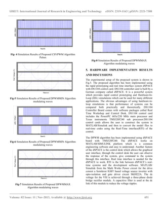
4. SIMULATION RESULTS AND DISCUSSIONS
To validate the proposed PWM algorithms, numerical
simulation is performed using Matlab-Simulink. To maintain
constant average switching frequency, the switching frequency
of SVPWM algorithm is taken as 10KZ.For simulation, dc
link voltage is taken as 600 V. The simulation results of the
conventional SVPWM algorithm is shown in Fig.3 – Fig4
.Here, modulating waveforms and pole voltages of the inverter
have shown. From the results it is concluded that SVPWM
algorithm generates continuous modulating wave andhence
continuous pulses to the inverter and hence gives more
switching losses in the inverter.
Fig-3 Simulation Results of CSVPWM Algorithm modulating
waves](https://image.slidesharecdn.com/implementationofdspacecontrolleddpwmbased-160805140503/85/Implementation-of-d-space-controlled-dpwm-based-3-320.jpg)
![IJRET: International Journal of Research in Engineering and Technology eISSN: 2319-1163 | pISSN: 2321-7308
__________________________________________________________________________________________
Volume: 02 Issue: 11 | Nov-2013, Available @ http://www.ijret.org 453
during the period of clamping are eliminated. There by
reducing switching losses to 1/3rd
with the CSVPWM.
Moreover, the proposed algorithm uses sector and angle
calculations requires the angle and sector calculations and
hence involved rigorous calculation taken by the controller.
From the test done, control of induction motor was
successfully implemented using dSPACE which means this
process is feasible. Speed of the Induction motor is controlled
successfully by varying the frequency or voltage by declaring
these two as control parameters in the dSPACE control desk
without disturbing the hard ware setup which is already
running.
ACKNOWLEDGMENTS
The authors are thankful to the AICTE and Management of
Rajeev Gandhi Memorial College of Engg And Tech, Andhra
Pradesh, India for sanctioning fund to carry out this work
under RPS scheme and providing necessary facilities to carry
this work.
REFERENCES
[1] Joachim Holtz, “Pulse width modulation – A survey”
IEEE Trans. Ind. Electron.., vol. 39, no. 5, Dec 1992,
pp. 410-420.
[2] Grahamme Holmes and T.A. Lipo, “Pulse width
modulation for power converters” IEEE press, 2004.
[3] Heinz Willi Vander Broeck, Hnas-Christoph Skudelny
and Georg Viktor Stanke, “Analysis and realization of a
pulse width modulator based on voltage space vectors”
IEEE Trans. Ind. Applicat., vol. 24, no. 1, Jan/Feb 1988,
pp. 142-150.
[4] P.G. Handley and T.J. Boys, “Space vector modulation:
An engineering review” IEE 4th
International
Conference on Power Electronics and Variable Speed
Drives, Conf Pub 324, 1990, pp. 87-91.
[5] G. Narayanan and V.T. Ranganathan, “Triangle
comparison and space vector approaches to pulse width
modulation in inverter fed drive”, Journal of Indian
Institute of Science, Sept/Oct 2000, pp. 409-427.
[6] Ahmet M. Hava, Russel J. Kerkman and Thomas A.
Lipo, “Simple analytical and graphical methods for
carrier-based PWM-VSI drives” IEEE Trans. Power
Electron., vol. 14, no. 1, Jan 1999, pp. 49-61.
[7] Ahmet M. Hava, Russel J. Kerkman and Thomas A.
Lipo, “A high-performance generalized discontinuous
PWM algorithm” IEEE Trans. Ind. Applicat., vol. 34,
no. 5, Sep/Oct 1998, pp. 1059-1071.
[8] Keliang Zhou and Danwei Wang, “Relationship
between space-vector modulation and three-pahse
carrier-based PWM: A comprehensive analysis” IEEE
Trans. Ind. Electron., vol. 49, no. 1, Feb 2002, pp. 186-
196.
BIOGRAPHIES
J.Jona is born in 1983 in India. Presently she
is doing post graduation in Power Electronics
and Electrical drives Specialization at RGM
College of Engineering and Technology,
Nandyal. Her main areas of interest include
Induction motor drives, Electrical machines,
power Electronic converters and Power Electronic Drives
E-mail: jona_jana@yahoo.co.in
Y.Chintu Sagar is born in 1989 in India .He
is graduated from RGM College of
Engineering and Technology, Nandyal in
2010.Presently he is doing post graduation in
Power Electronics and Electrical drives
Specialization at RGM College of
Engineering and Technology, Nandyal. His main areas of
interest include Induction motor drives, Electrical machines,
power Electronic converters and Power Electronic Drives E-
mail: chintu215@gmail.com
Dr. K.Sri Gowri received the B.Tech degree
from SVU college of Engineering, Tirupati in
1997, the M.Tech degree from RGM College
of Engineering and Technology, Nandyal and
has been awarded Ph.D in the area of Power
Electronic Control of Electric Drives from
JNTU Kakinada in 2010. She is currently Professor in the
Department of EEE in RGMCET, Nandyal, A.P. Her areas of
interest include Power Electronics, Pulse Width Modulation
Techniques, Drives and Control, Renewable Sources of
Energy. E-mail: gowrivasu.3@gmail.com
G. Kumaraswamy is born in 1983 in India.
He is graduated from JNTU University in
2005 and pursued Post graduation from the
same university. He is currently working as a
Assistant professor in the department of
electrical and electronics engineering R.G.M
college of engineering and technology, Nandyal, Andhra
Pradesh, India. He has eight years of teaching experience. He
has attended several National workshops. His main areas of
research include Photovoltaic cells, multilevel inverters. Email:
kumar1718@gmail.com](https://image.slidesharecdn.com/implementationofdspacecontrolleddpwmbased-160805140503/85/Implementation-of-d-space-controlled-dpwm-based-6-320.jpg)

The document discusses the implementation of a dspace-controlled induction motor drive using a discontinuous pulse width modulation (dpwm) algorithm, which enhances performance by improving harmonic distortion and DC bus utilization compared to conventional methods. It details the advantages of dpwm in reducing switching losses during motor control and presents simulation and experimental results to validate the proposed approach. The study concludes successful motor control achieved through dspace systems, emphasizing the effectiveness of the dpwm strategy for various modulation indices.


![3.[14 28]space vector based dual zero-vector random centered distribution pwm...](https://cdn.slidesharecdn.com/ss_thumbnails/3-14-28spacevectorbaseddualzero-vectorrandomcentereddistributionpwmalgorithmfordirecttorquecontrolofinductionmotordriveforreducedacousticalnoise-111203185000-phpapp02-thumbnail.jpg?width=640&height=640&fit=bounds)


