Download as PDF, PPTX

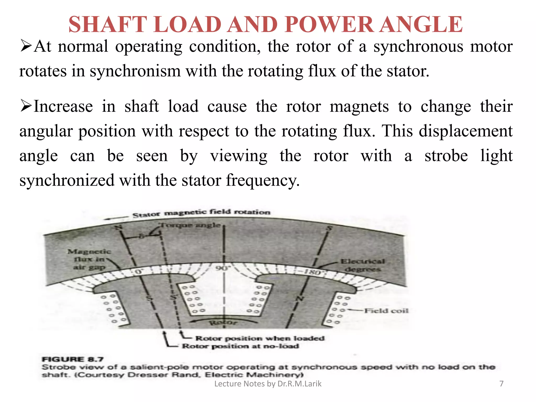
![➢As the machine is loaded, the rotor changes its relative position with
respect to the rotating flux of the stator, lagging behind it by angle δ .
➢Angle δ, expressed in electrical degrees, is called the power angle, load
angle, or torque angle.
➢A synchronous motor operates at the same average speed for all values of
load from no-load to its peak load.
➢When the load on a synchronous motor is increased, the motor slows
down just enough to allow the rotor to change its angular position in
relation to the rotating flux of the stator, and then goes back to synchronous
speed. [???]
➢Similarly, when the load is removed, it accelerates just enough to cause
the rotor to decrease its angle of lag in relation to the rotating flux, and then
goes back to synchronous speed.
➢When the peak load that the machine can handle is exceeded, the rotor
pulls out of synchronism. Lecture Notes by Dr.R.M.Larik 8](https://image.slidesharecdn.com/synhronousmotorequivalentcircuit-200710090444/75/Synhronous-motor-equivalent-circuit-8-2048.jpg)

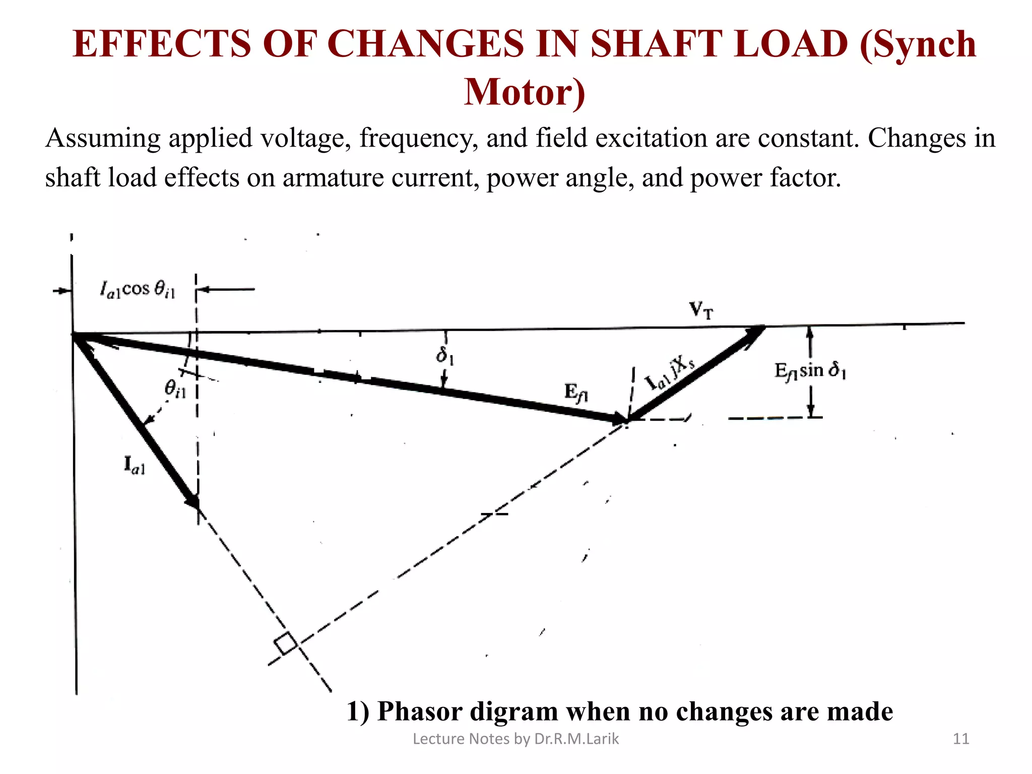
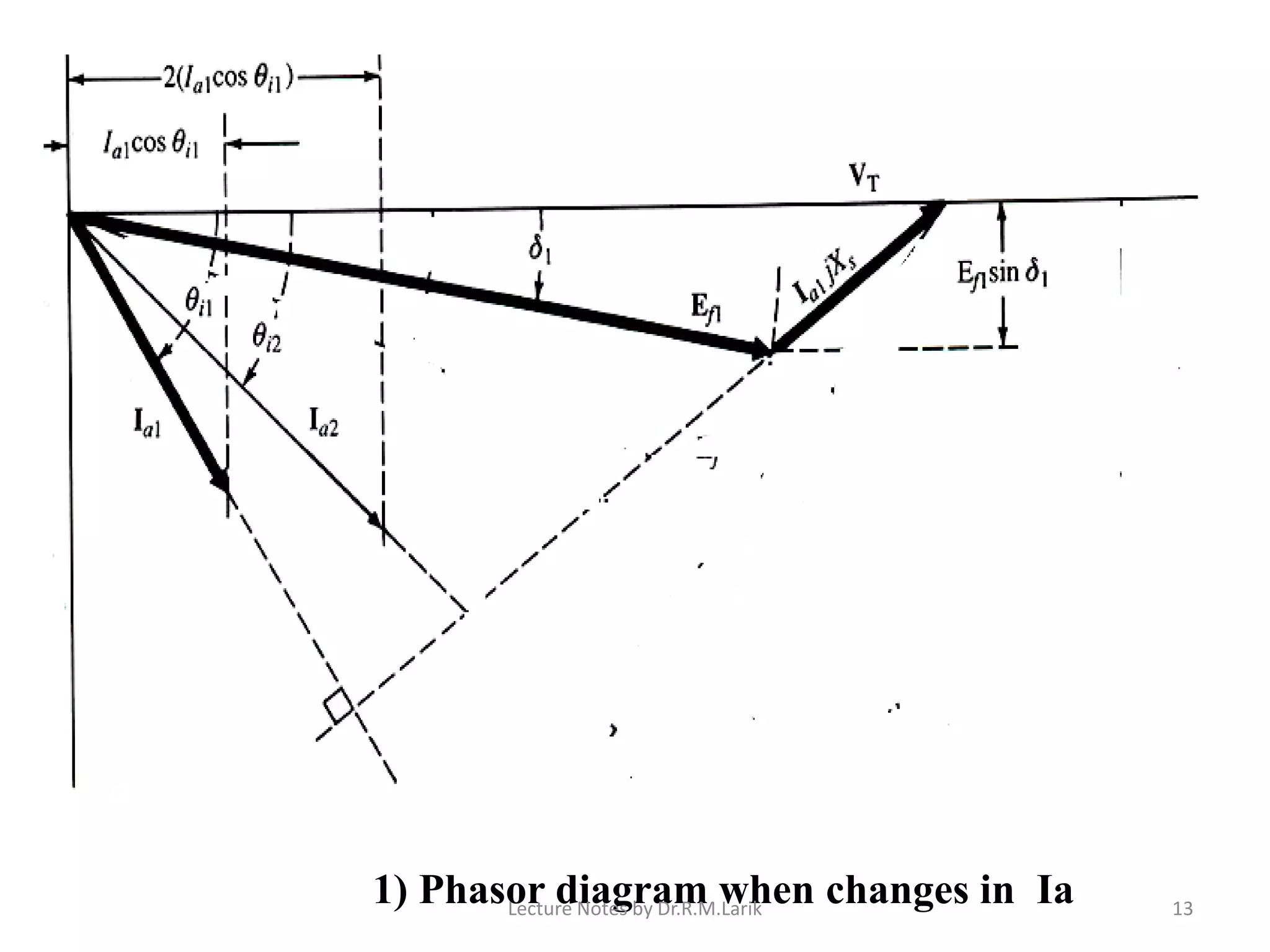
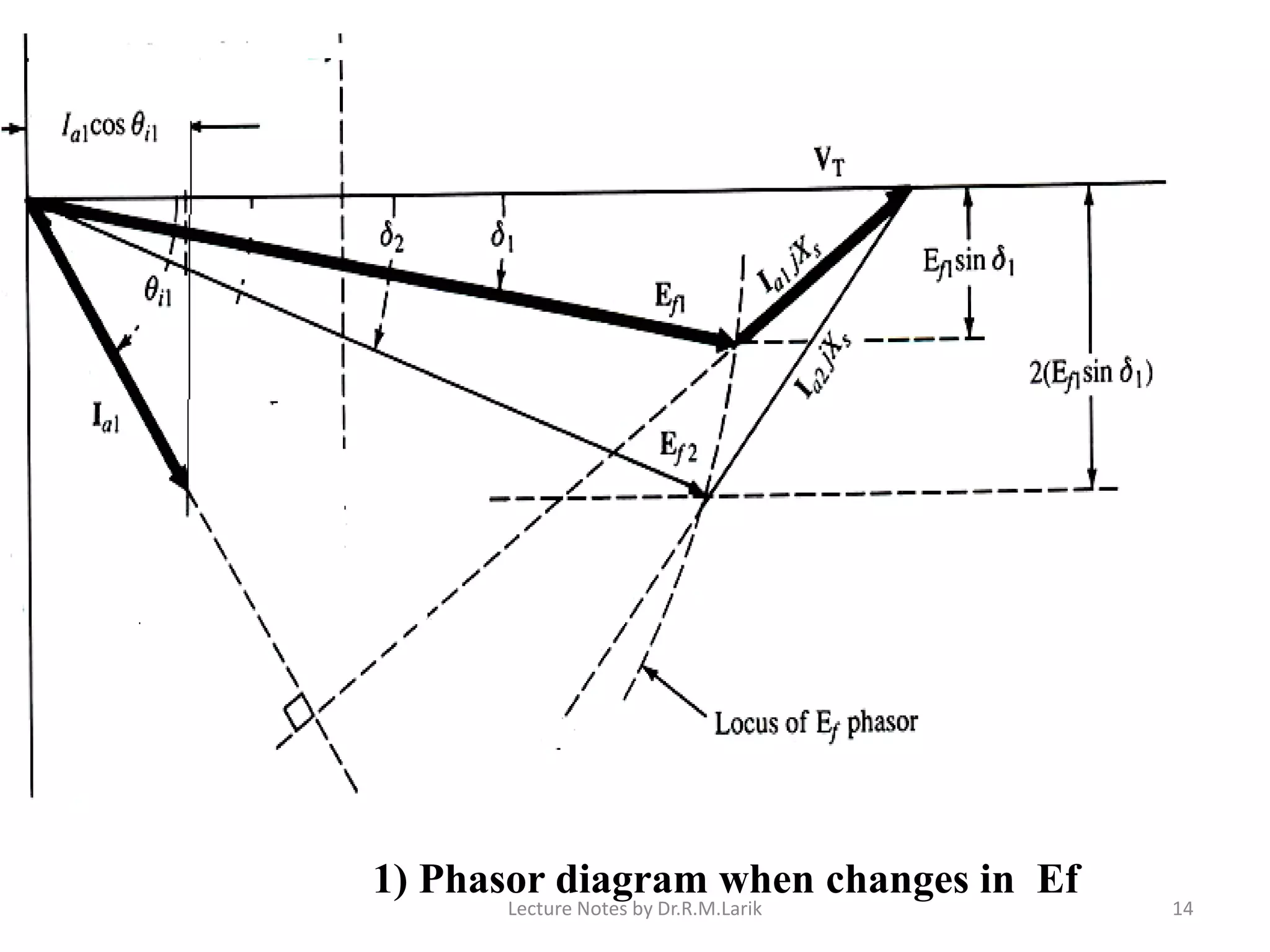
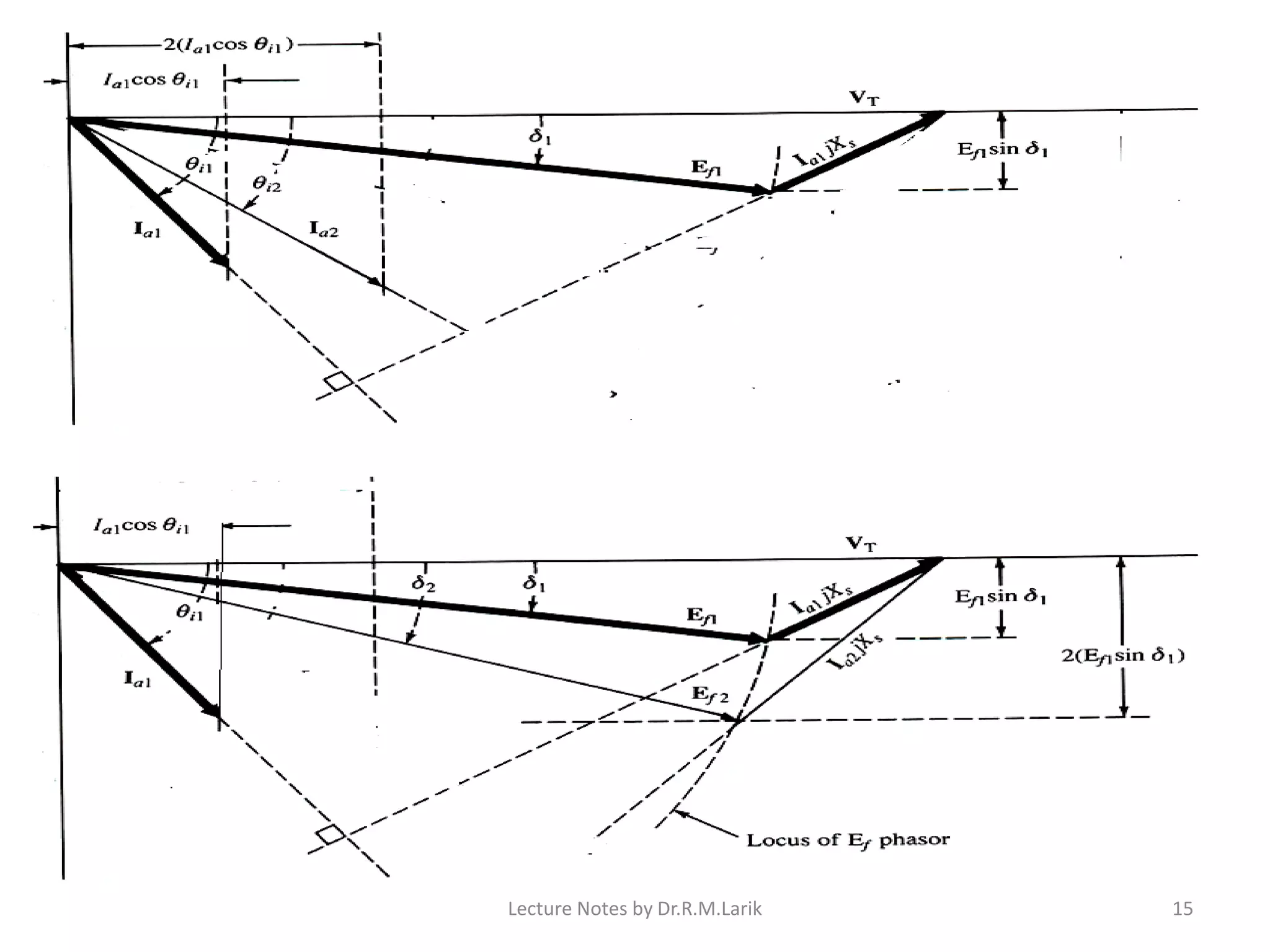
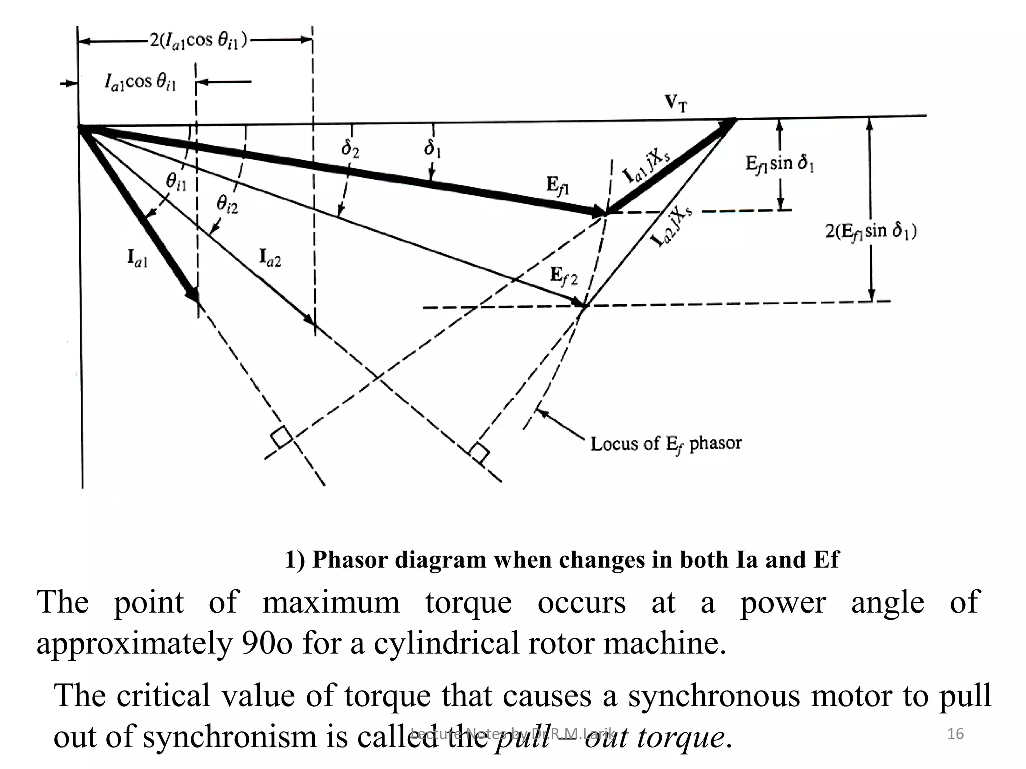
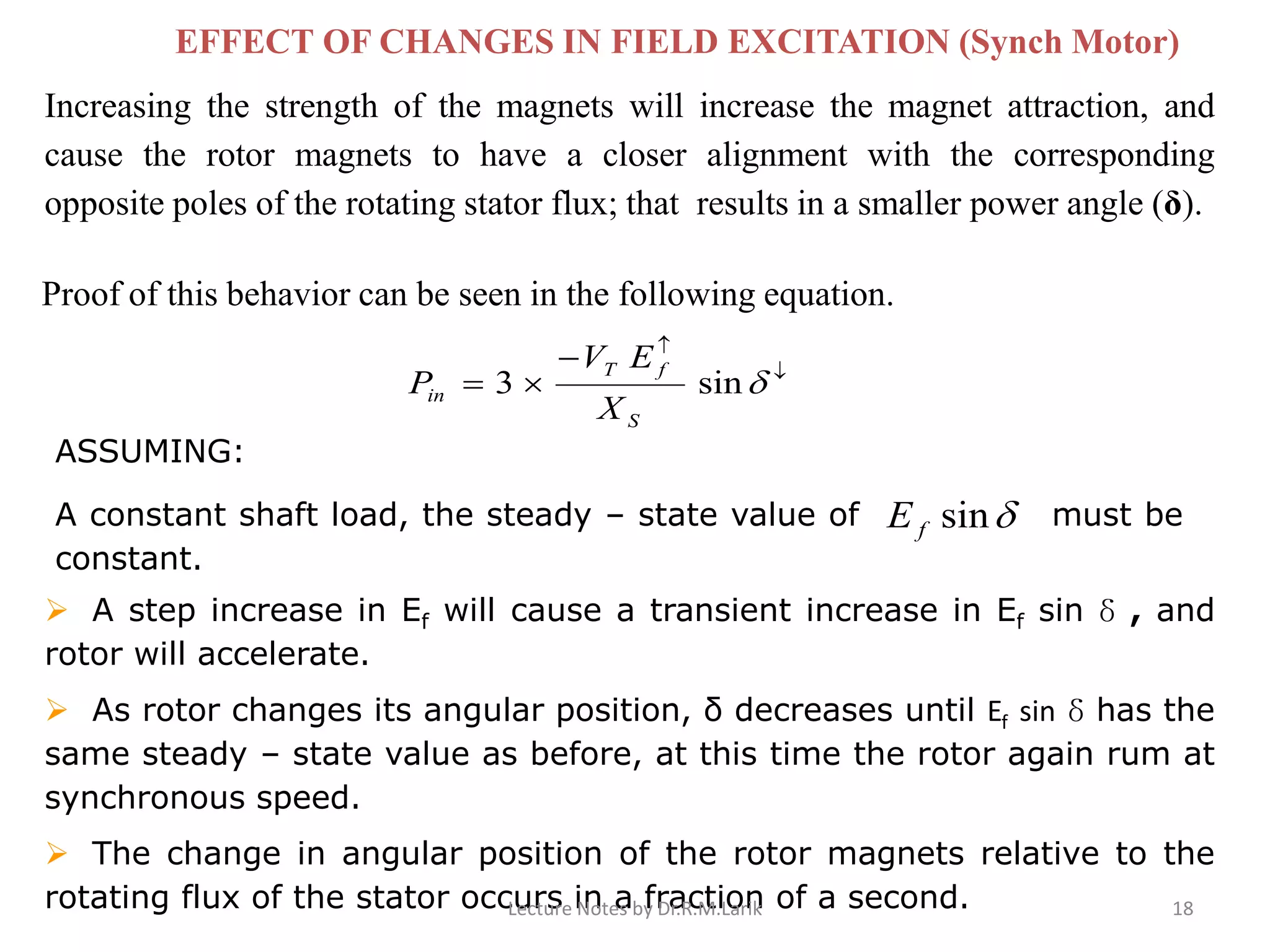


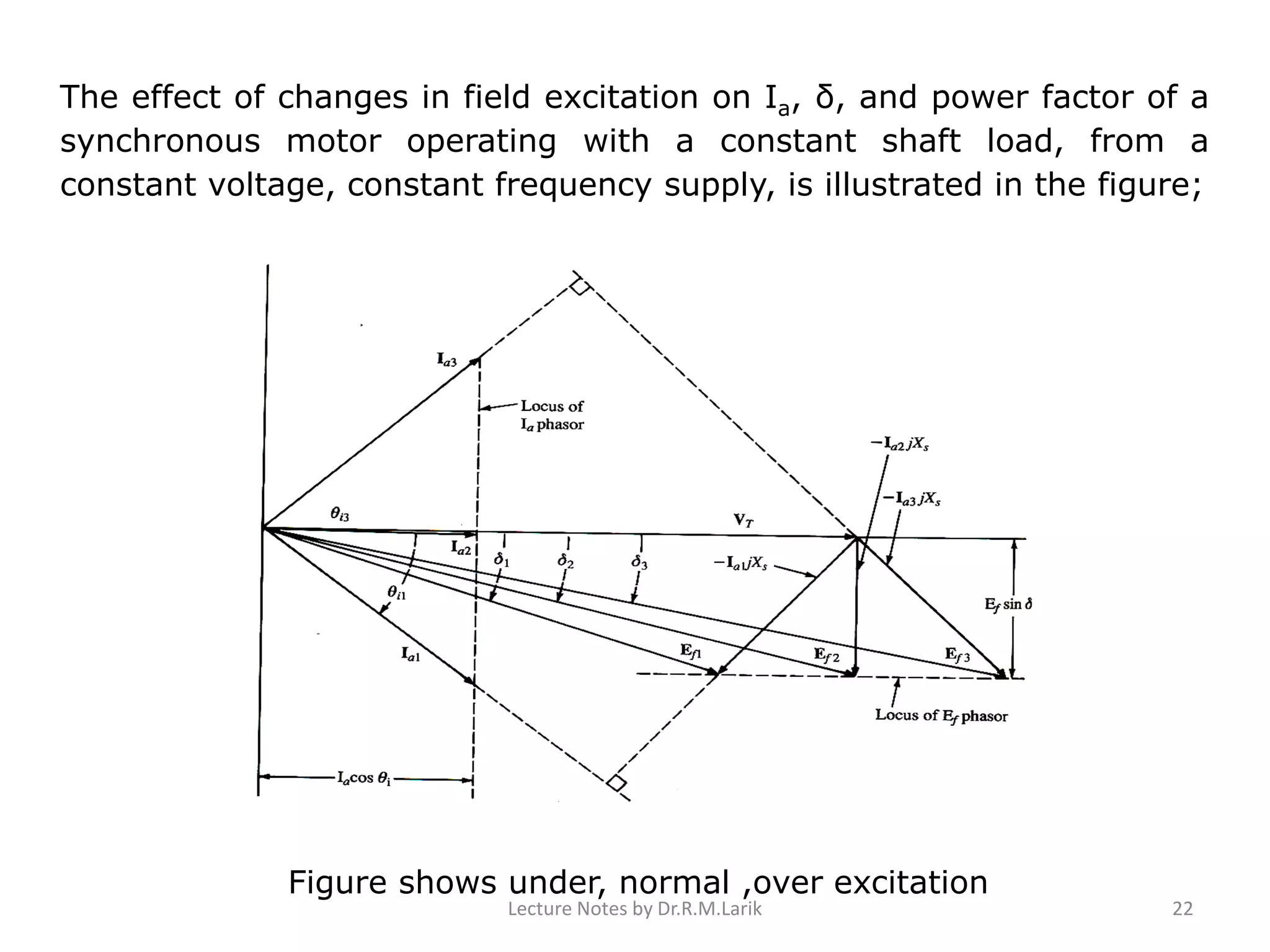

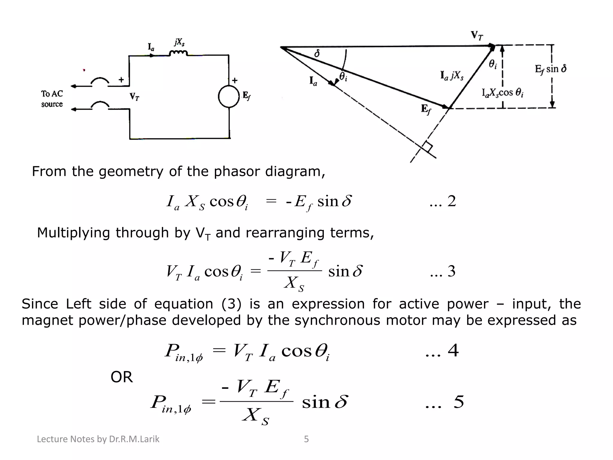
1) The document describes the equivalent circuit model and power equations of a synchronous motor. It discusses how changes in shaft load, field excitation, and armature current affect the power angle, armature current, and power factor. 2) Increasing shaft load causes the power angle to increase and leads to a decrease in power factor. Increasing field excitation causes the power angle to decrease and can change the power factor from lagging to leading. 3) The document contains diagrams of the phasor relationships and how they change under different operating conditions, including under, normal, and over excitation levels.


