Download to read offline
![a combination of the two adjacent active switching
vectors and one or both of the zero vectors
3.DESIGN OF COMPONENTS
Clark transformation or αβγ transformation is a
mathematical transformation employed to simplify the
analysis of three-phase circuits. One very useful
application of the αβ transformation is the generation of
the reference signal used for space vector modulation
control of three-phase inverters.
Rotating Space Vector, U(t) is represented as
U(t)=(Ua+ Ube^(j(2/3)∗pi)+ Uce^((j(−2/3)∗pi)2/3 )
The voltage vector V1 is given by the
1 =
2𝑉dc
3
As shown in Figure 1, current control under hysteresis
band principle operation in generating the PWM
The general equation for voltage vector,
switching signals. The actual phase current is compared
to sinusoidal wave references current which are
produced by the control circuit. The upper switch (S1) is
2
𝑉𝑛 =
3
𝑉𝑑𝑐
∗ 𝑒 j(n−1)∗pi/3
turned off and the lower switch (S4) is turned on when
the actual current exceeds the higher band limit. As a
results, the output voltage changes from +0.5Vdc to -
0.5Vdc. The actual current start to decrease and drop
until it crosses the lower band limit. At this time, the
lower switch is turned off and the upper switch is
turned on. Then, the output voltage changes from -0.5
Vdc to +0.5 Vdc and the current starts to increase. This
process is then continuously repeated.
Principle Of SVPWM Based Induction Motor
Drive
A space vector is a sinusoidal voltage vector with
constant amplitude and rotating at constant frequency.
It is used for the creation of alternating current (AC)
waveforms; most commonly to drive 3 phase AC
powered motors at varying speeds from DC.
Figure 2 –abc to dq transformation
To implement space vector modulation, a reference
signal Vref is sampled with a frequency fs (Ts = 1/fs). The
reference signal may be generated from three separate
phase references using the αβ transform as shown in
Figure 2. The reference vector is then synthesized using
Three-phase VSI generates eight switching states which
include six active and two zero states. These vectors form
a hexagon which consisting of six sectors spanning 60
each. The reference vector which represents three-phase
sinusoidal voltage is generated using SVPWM by switching
between two nearest active vectors and zero vector.
Figure 3- Switching sectors of three phase inverter
To calculate the time of application of different vectors,
consider Figure3, depicting the position of differently
available space vectors and the reference vector in the first
sector. Table 1 shows the switching states correponding to
International Research Journal of Engineering and Technology (IRJET) e-ISSN: 2395-0056
Volume: 09 Issue: 11 | Nov 2022 www.irjet.net p-ISSN: 2395-0072
pulse-widthmodulation[1]. Space vector based
hysteresis controller for VSI fed IM drive is introduced.
Hysteresis current controller has a simple
implementation, fast transient response and direct
limitation of the peak current. Hysteresis current
control is relatively a simple method for PWM technique
with comparatively good current loop response.
𝑉
Figure 1 –Hysteresis current control
© 2022, IRJET | Impact Factor value: 7.529 | ISO 9001:2008Certified Journal | Page 356](https://image.slidesharecdn.com/irjet-v9i1153-221208093604-bdaac4a8/75/Performance-Analysis-Of-Induction-Motor-For-Voltage-Mode-And-Current-Mode-Control-2-2048.jpg)

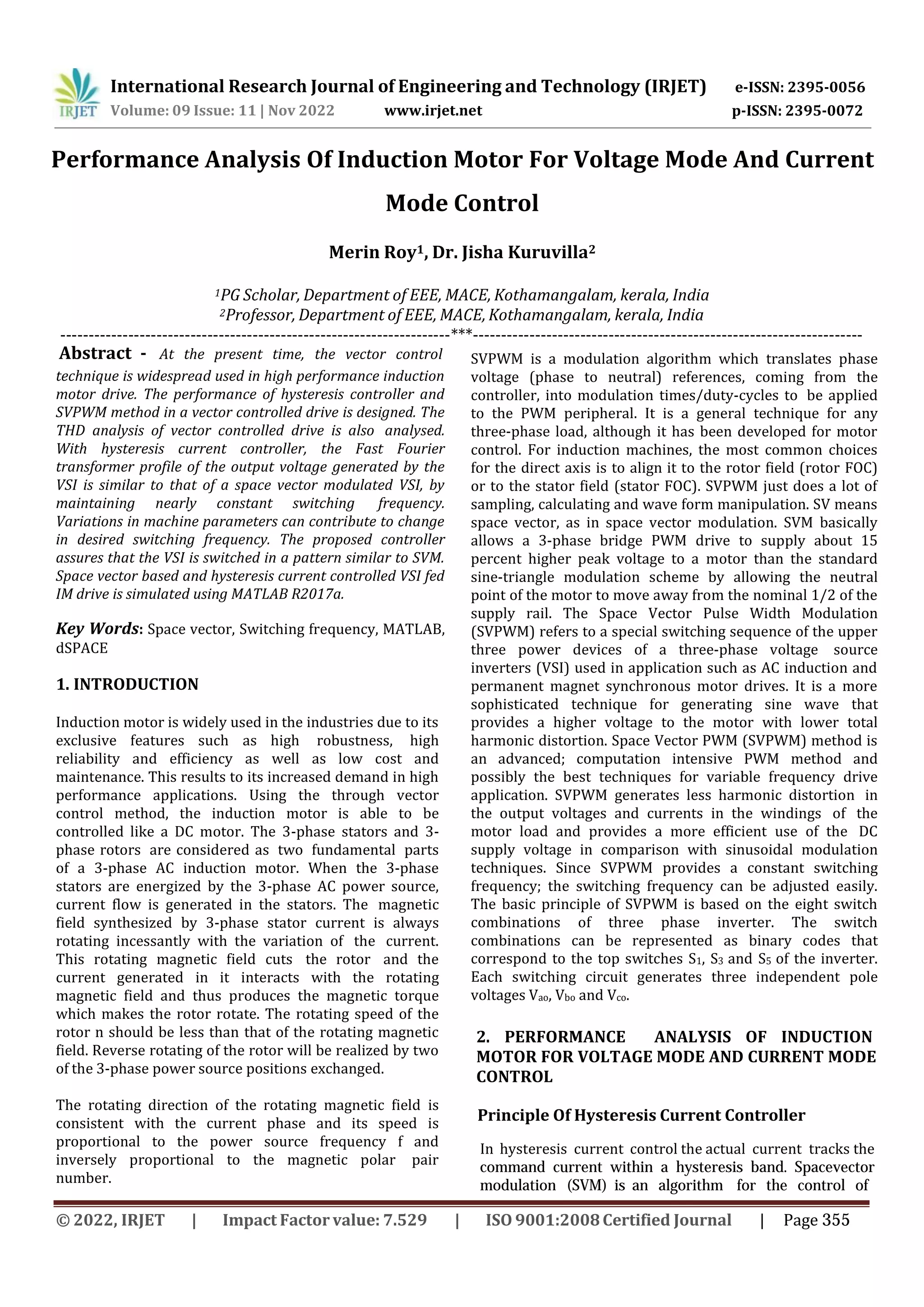
![Figure 22: THD of the output Voltage a) SVPWM
[[THD = 2.05 percent]] b) Hysteresis controller
[THD = 25.6 percent]
Switching Pulse
Figure 23: Switching Pulses a)SVPWM b)
Hysteresis controller
Figure 21-THD of the output Current a) SVPWM
[THD = 7.17 percent] b) Hysteresis controller
[THD=19.3percent]
International Research Journal of Engineering and Technology (IRJET) e-ISSN: 2395-0056
Volume: 09 Issue: 11 | Nov 2022 www.irjet.net p-ISSN: 2395-0072
Table 4 shows the comparison between SVPWM and
Hysteresis controlled modulation technique. It is
observed that THD of output current and
switching pulses of SVPWM is less compared to
Hysteresis controlled.
REAL TIME PULSE GENERATION
SIMULINK MODEL
Table4 -Comparison between SVPWM and
Hysteresis
4. EXPERIMENTAL SETUP WITH RESULT
With Real-Time Interface (RTI), you can easily run your
function models on the DS1104 R and D Controller
Board. You can configure all I/O graphically, insert the
blocks into a Simulink block diagram, and generate the
model code via Simulink Coder. The real-time model is
compiled, downloaded, and started automatically. This
reduces the implementation time to a minimum. The
experimental setup is shown below.
Figure 24 –Hardware Setup
Also observed the switching pulse of SVPWM and
hysteresis controlled for 0.0003 sec and analyzed
that switching pulse of hysteresis is more than that of
SVPWM controlled IM drive. There are 14
switching for a time period of 0.001 sec in SVPWM
method and for the same time period there are 44
switching for Hysteresis controlled.
© 2022, IRJET | Impact Factor value: 7.529 | ISO 9001:2008Certified Journal | Page 361](https://image.slidesharecdn.com/irjet-v9i1153-221208093604-bdaac4a8/75/Performance-Analysis-Of-Induction-Motor-For-Voltage-Mode-And-Current-Mode-Control-7-2048.jpg)
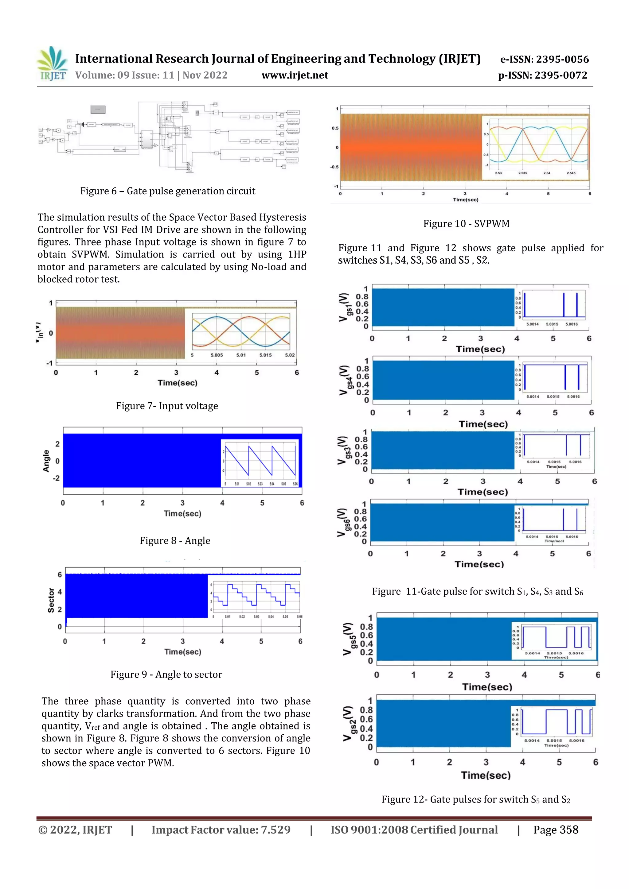
![Figure 25 – Generation of switching Pulse
International Research Journal of Engineering and Technology (IRJET) e-ISSN: 2395-0056
Volume: 09 Issue: 11 | Nov 2022 www.irjet.net p-ISSN: 2395-0072
For making simulink model, a svpwm is compared with
repeating sequence and the output is given to master bit
out block. For 6 switches the output pins are given as
C0 to C5 and the output of pulse is taken from digital
I/O connector from dspace connector panel. Figure 24
shows the simulink Master bit out blocks. The switching
pulse of S1 and S4 (first leg), S3 and S6(of second leg ) , S5
and S2 (of third leg)is shown in Figure. Switch S1, S4 , S3,
S6 , S5 and S2 has a frequency of 3kHz.
shows the simulink model of Pulse Generation of
Switches using Master bit out blocks. The switching pulse
of S1 and S4 (first leg), S3 and S6(of second leg ) , S5 and S2
(of third leg)is shown in Figure 26:(a),(b),(c) respectively.
Switch S1, S4 , S3, S6 , S5 and S2 has a frequency of 3kHz.
Figure 26- Switching Pulses and dead time for
switches a)S1, S4 ,b) S3, S6 and c)S5 ,S2
The pulses for first leg that is for the switch 1 and 4
anddead time of 20 msec are shown in figure 26. The
pulses are 180 degree out of phase. The pulses to the
switch 3 and 6 and dead time of 20 msec are shown in
figure 26 (b) and The pulses to the switch 5 and 2 and
dead time of 20 msec are shown in figure 26 (c) . Figure 5.6
shows the current waveform. of motor for the three phases.
Motor current of phase A in open loop is shown in
Figure 27. The other two are 120 degree phase shifted as
shown in Figure 27 .
CONCLUSION
A Matlab/Simulink model is done to implement
SVPWM for three-phase VSI. The VSI model is based
on space vector representation. Current control is done
by hysteresis current controller. Vector control and
hysteresis control of induction motor drive is simulated.
Speed of motor was maintained constant at varying
load using SVPWM control. Studied the switching
frequency variation, losses for SVPWM and hysteresis
based IM drive. Analysed the total harmonic distortion
of output current, voltage and switching pulses for
both SVPWM and hysteresis controlled IM drive.
Hardware implementation is done with dSPACE ds1104
controller.
Figure 27 - Current waveform Ia, Ib and Ic
REFERENCES
[1] Sandeep Jayaprakasan, Ashok S., and Rijil
Ramchand,”Current Error Space Vector Based
Hysteresis Controller for VSI Fed PMSM Drive,
IEEE Trans. Power Electron., Vol. 35, No. 10,
October 2020.
[2] M. P. Kazmierkowski and L. Malesani, ”Current
control techniques for three-phase voltage-source
PWM converters: A survey”, in IEEE Trans. Ind.
Electron., vol. 45, no. 5, pp. 691703, Oct. 2000.
[3] P. Tekwani, R. Kanchan, and K. Gopakumar, ”Novel
current error space phasor based hysteresis
controller using parabolic bands for control of
switching frequency variations,” in IEEE
Transactions on Power Electronics,vol. 54, no.
5,Oct. 2007.
[4] R. Ramchand, K. Gopakumar, C. Patel, K.
Sivakumar, A. Das, and H. AbuRub,”Online
computation of hysteresis boundary for constant
switching frequency current-error space-vector-
© 2022, IRJET | Impact Factor value: 7.529 | ISO 9001:2008Certified Journal | Page 362](https://image.slidesharecdn.com/irjet-v9i1153-221208093604-bdaac4a8/75/Performance-Analysis-Of-Induction-Motor-For-Voltage-Mode-And-Current-Mode-Control-8-2048.jpg)
![International Research Journal of Engineering and Technology (IRJET) e-ISSN: 2395-0056
Volume: 09 Issue: 11 | Nov 2022 www.irjet.net p-ISSN: 2395-0072
[5] Joseph Peter , Srikar Krishnatheeram and Rijil
Ramchand,”Novel Hysteresis Regulation Strategy
for a Two-level Inverter Fed Induction Motor
Drive to Achieve Nearly Constant Switching
Frequency,, IETE Journal of Research,, vol. 41, no.
1, pp. 9196, Feb. 1994., Aug. 2015.
[6] A. Consoli, S. Musumeci, A. Raciti, and A.
Testa,”Sensorless vector and speed control of
brushless motor drives, IEEE Trans. Ind. Electron.,
vol. 41, no. 1, pp. 9196, Feb. 1994., Aug. 2015.
2016.
[7] M. Baiju, K. Mohapatra, R. Kanchan, P. Tekwani,
and K. Gopaku mar A space phasor based current
hysteresis controller using adjacent inverter
voltage vectors with smooth transition to six step
op eration for a three phase voltage source
inverter, IEEE Trans. Power Electron.,vol. 15, no.
1, pp. 3647, 2005.
[8] Srikanthan Sridharan and Philip T. Krein, Fellow,
Minimization of System-Level Losses in VSI-Based
Induction Motor Drives: Offline Strategies, , IEEE
Transactions on Industry
based hys teresis controller for VSI fed IM drives,
IEEE Trans. Power Electron., vol. 27, no. 3,
pp. 15211529, Mar. 2012.
[9] V. M. Mistry, S.Waiker, K. Gopakumar, L.
Umanand, and V. Ranganathan,V. M. Mistry,
S.Waiker, K. Gopakumar, L. Umanand, and V.
Ranganathan, A multi axis space phasor based
current hysteresis controller for PWM
inverters, EPE J,, vol. 10, no. 1, pp. 1725, 2000.
© 2022, IRJET | Impact Factor value: 7.529 | ISO 9001:2008Certified Journal | Page 363](https://image.slidesharecdn.com/irjet-v9i1153-221208093604-bdaac4a8/75/Performance-Analysis-Of-Induction-Motor-For-Voltage-Mode-And-Current-Mode-Control-9-2048.jpg)

This document discusses the performance analysis of an induction motor using voltage mode and current mode control. It compares hysteresis current control and space vector pulse width modulation (SVPWM). Hysteresis control directly limits current peaks but SVPWM provides higher voltage output and lower harmonic distortion. The document simulates an induction motor drive using SVPWM-based hysteresis current control in MATLAB. Key steps include Clark transformation to generate reference signals, switching between active and zero vectors to synthesize the reference signal, and using hysteresis control to generate PWM signals from current errors. Simulation results show the SVPWM controller provides good speed and current regulation for the induction motor.