Downloaded 485 times
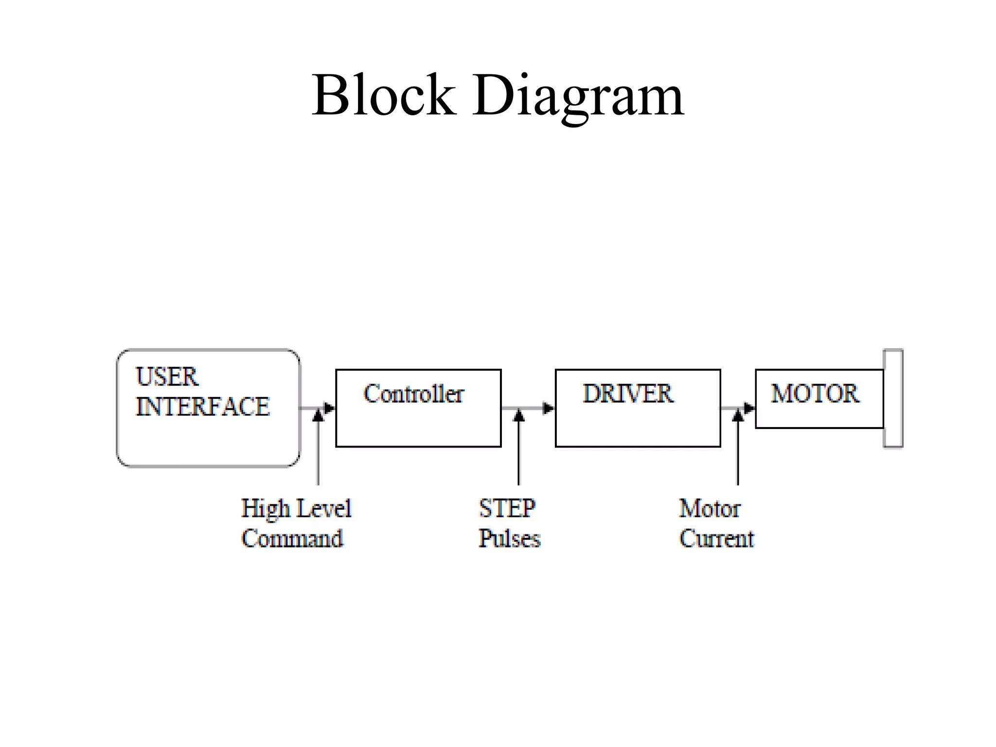


This document describes a microcontroller-based stepper motor controller that can control the motor's direction, speed, and number of revolutions using tactile switches. It includes a block diagram and descriptions of the main components - an AT89C51 microcontroller, voltage regulator, crystal oscillator, hex converter, and bipolar stepper motor. The controller uses half-step drive to accurately control the motor. It can be simulated using Proteus software and interfaced with a computer for keyboard control of the motor's speed. Stepper motors are described in comparison to conventional motors.
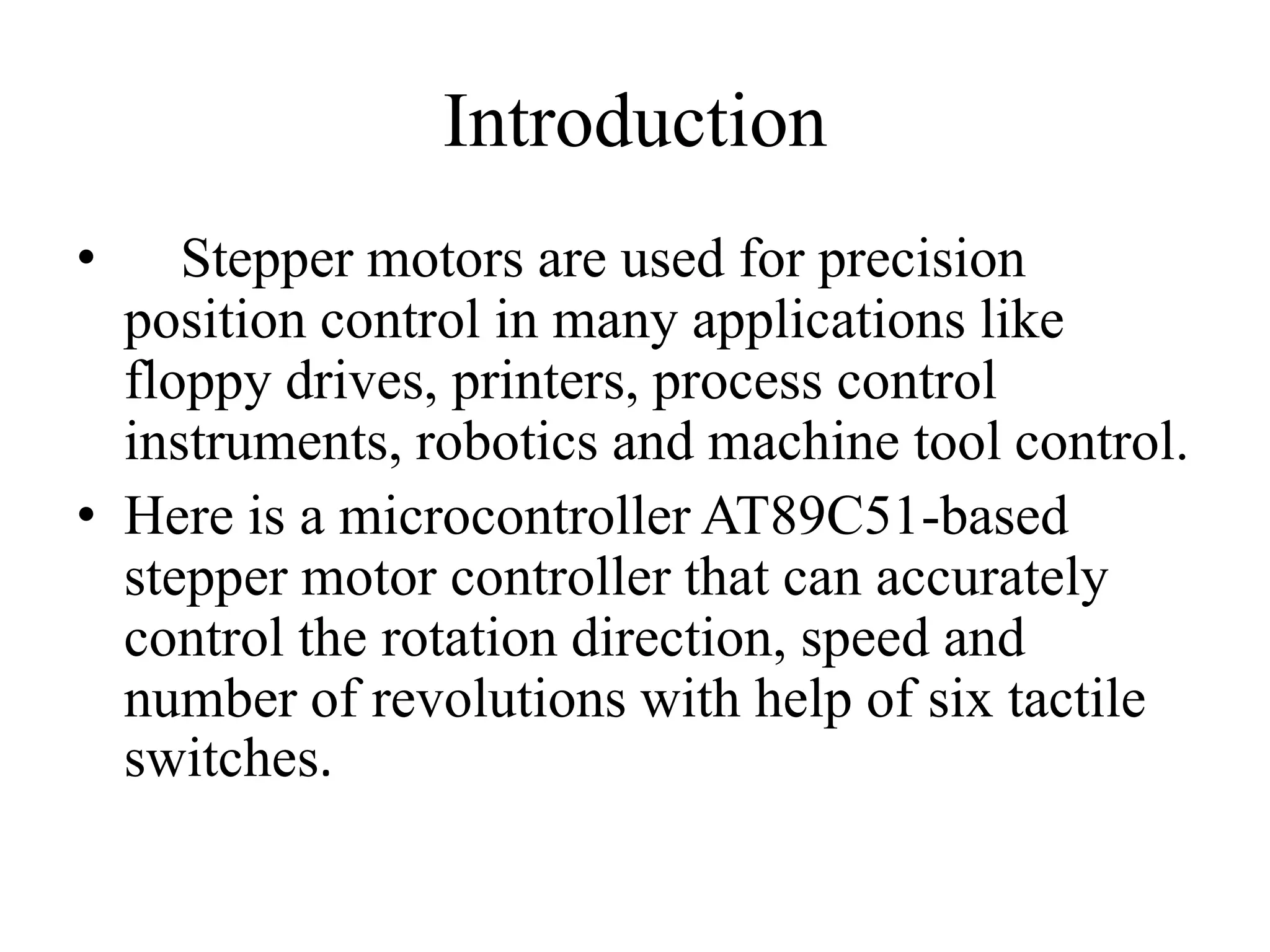
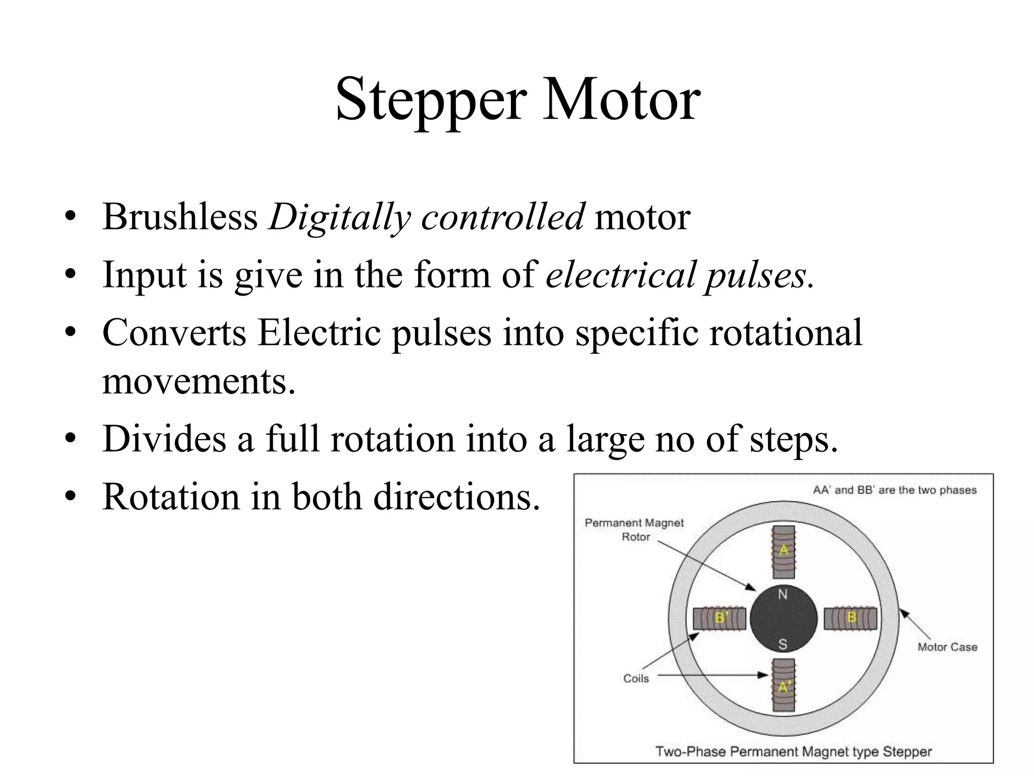
Project guide by Mr. Pramod Kumar, introduction to stepper motors and AT89C51 microcontroller.
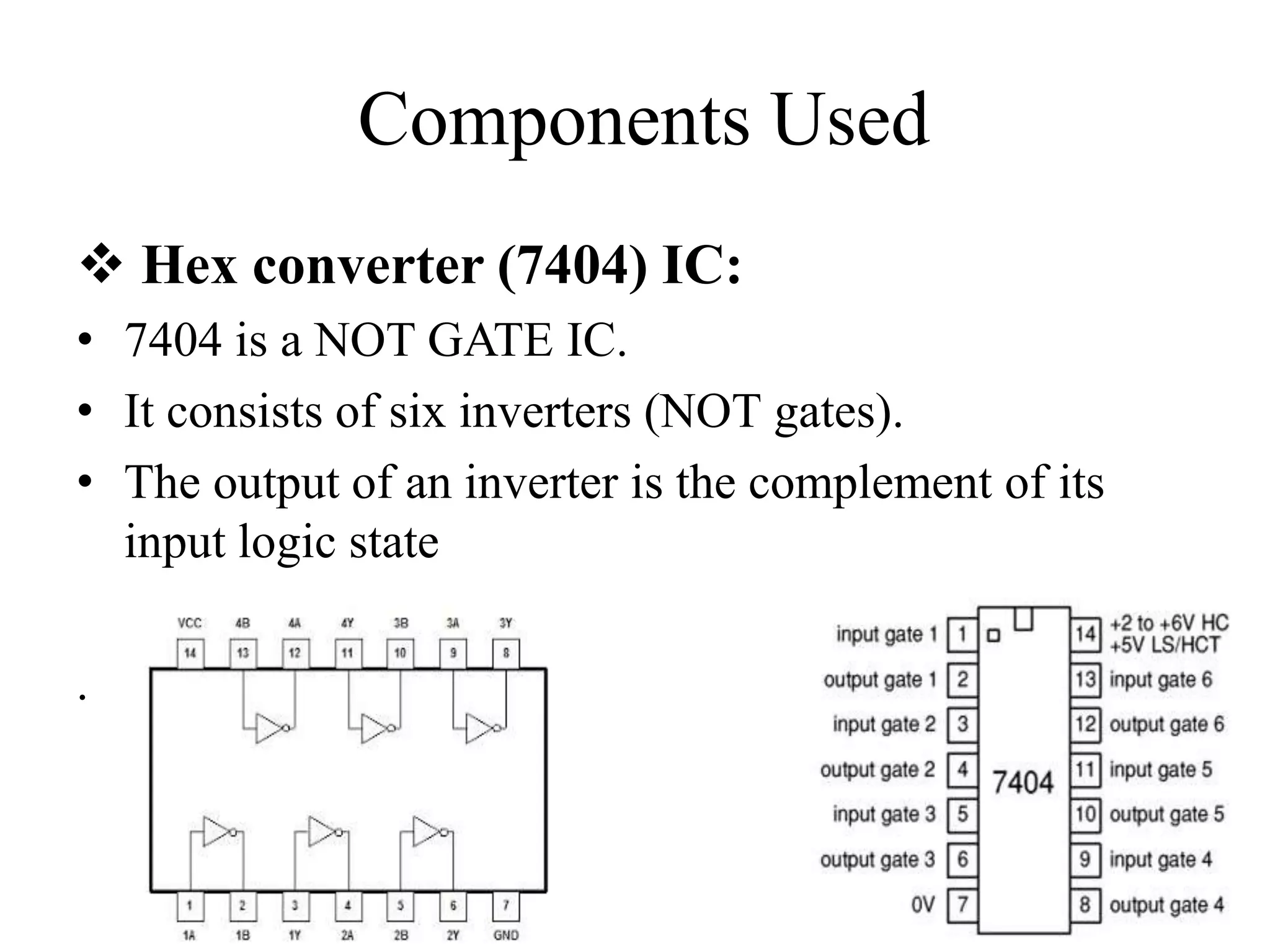
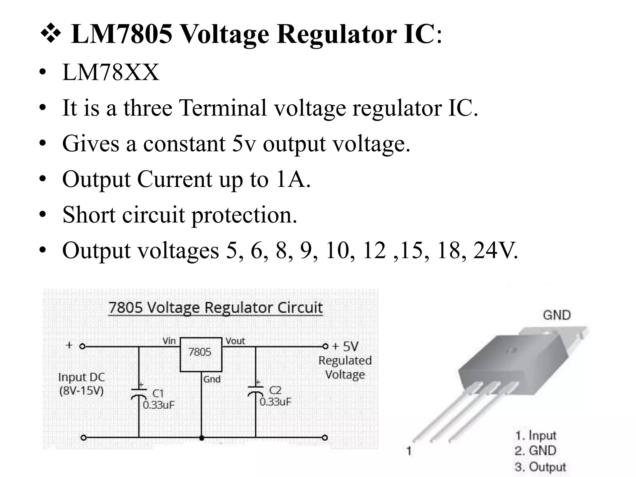
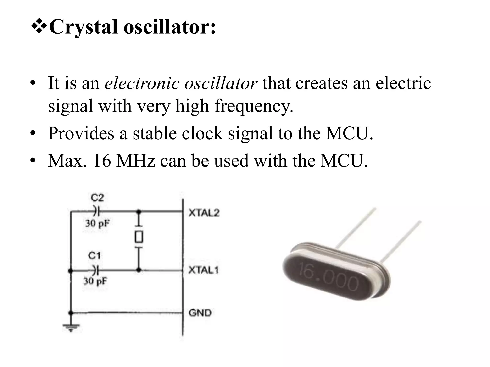
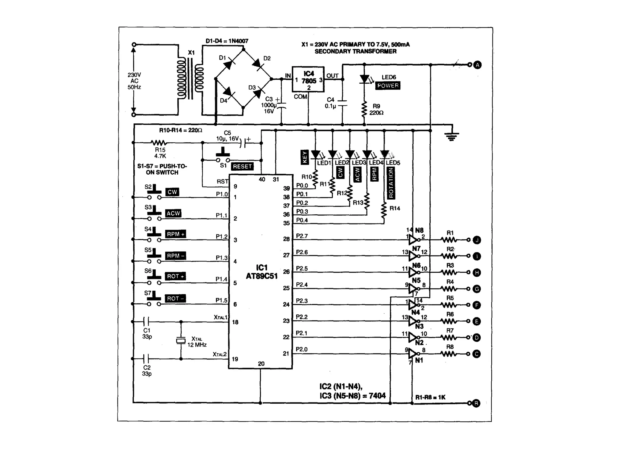
Block diagram overview, hex converter and voltage regulator details, and use of a crystal oscillator.
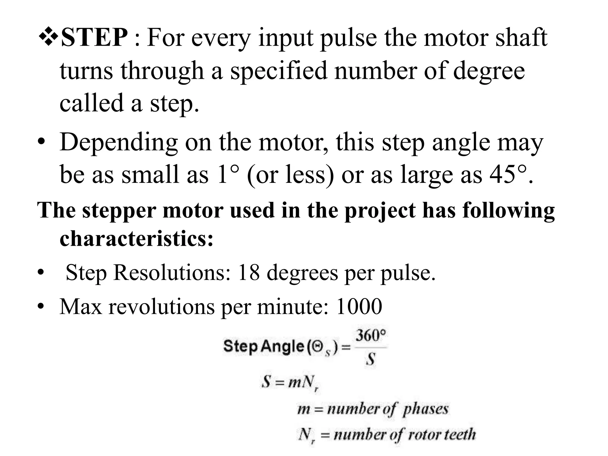
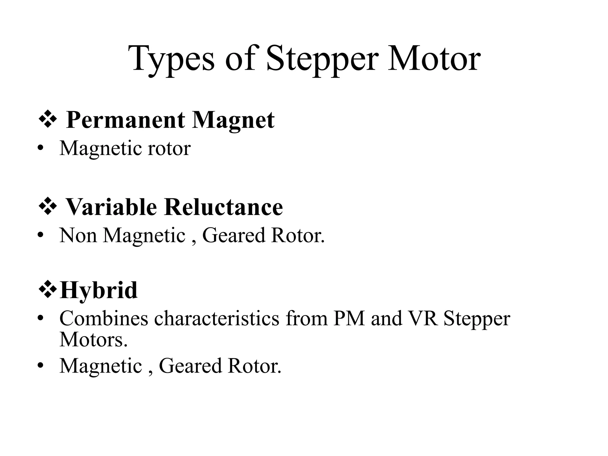
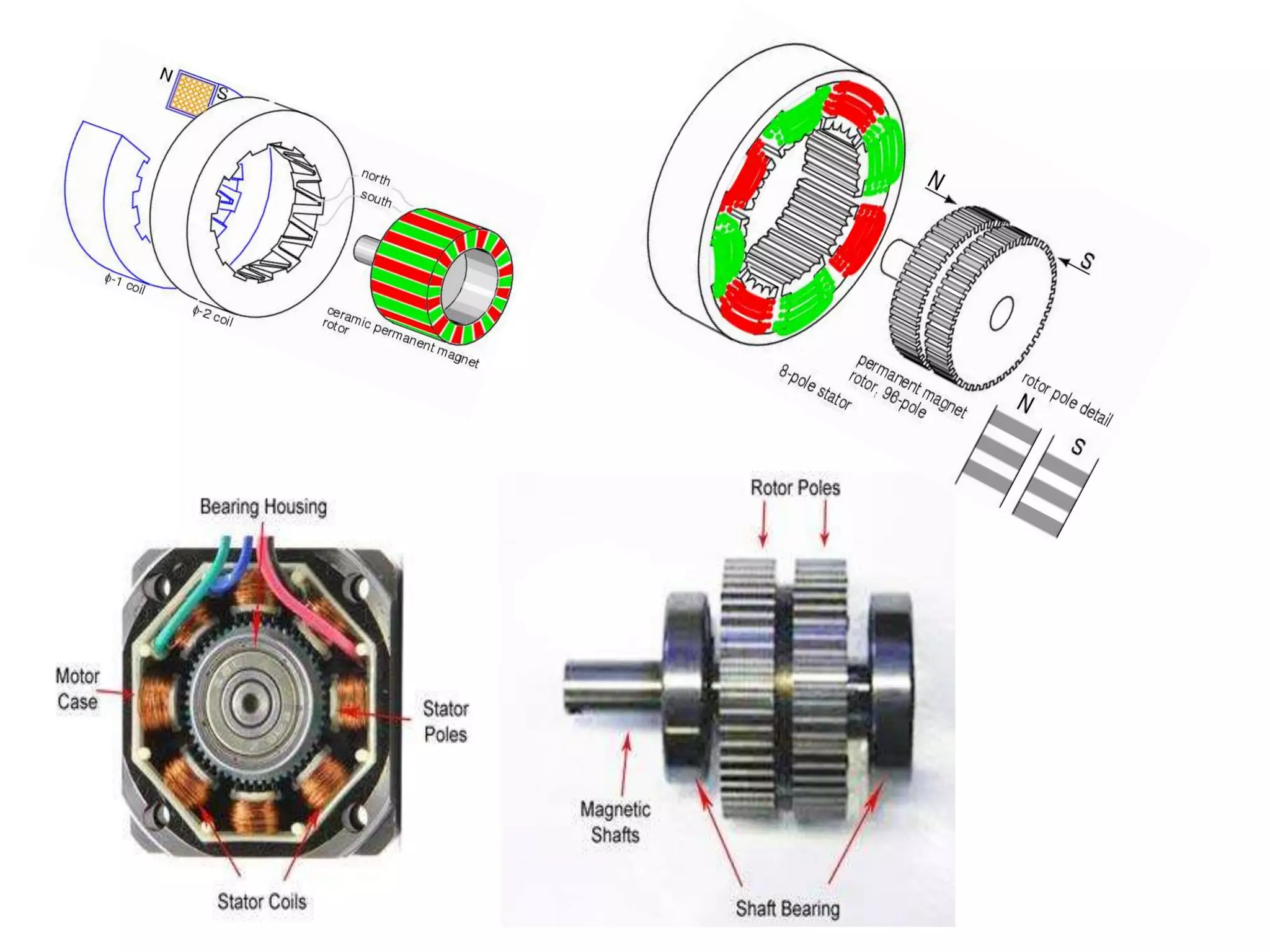
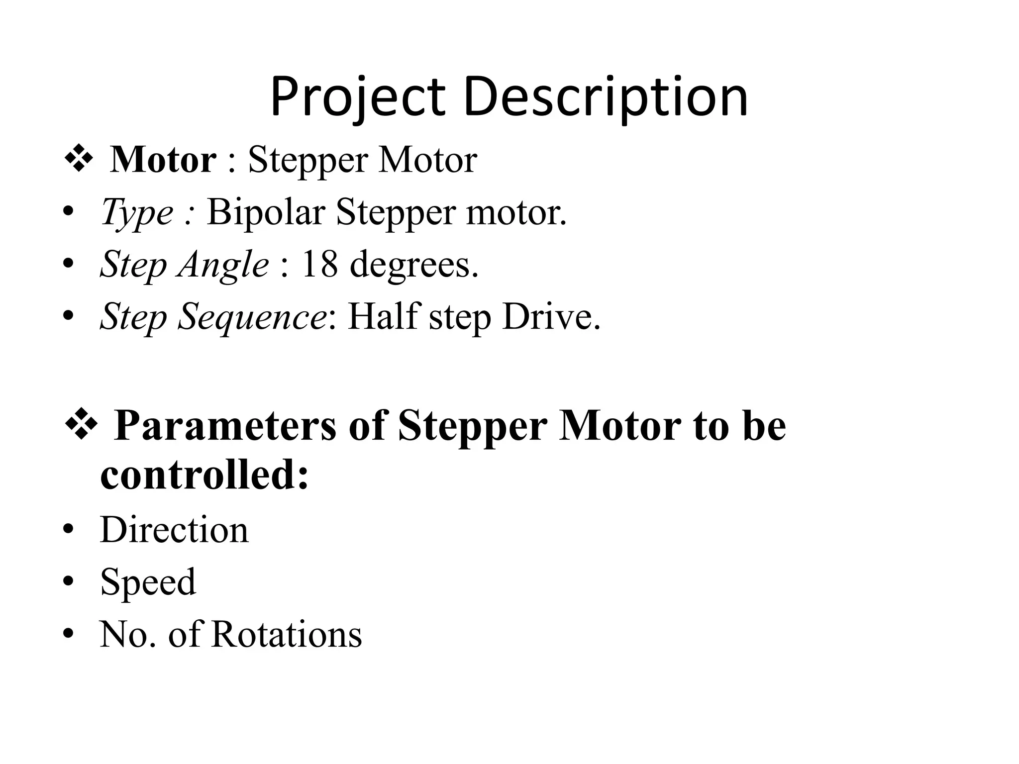
Explanation of stepper motor operation, step angles, and types of stepper motors.
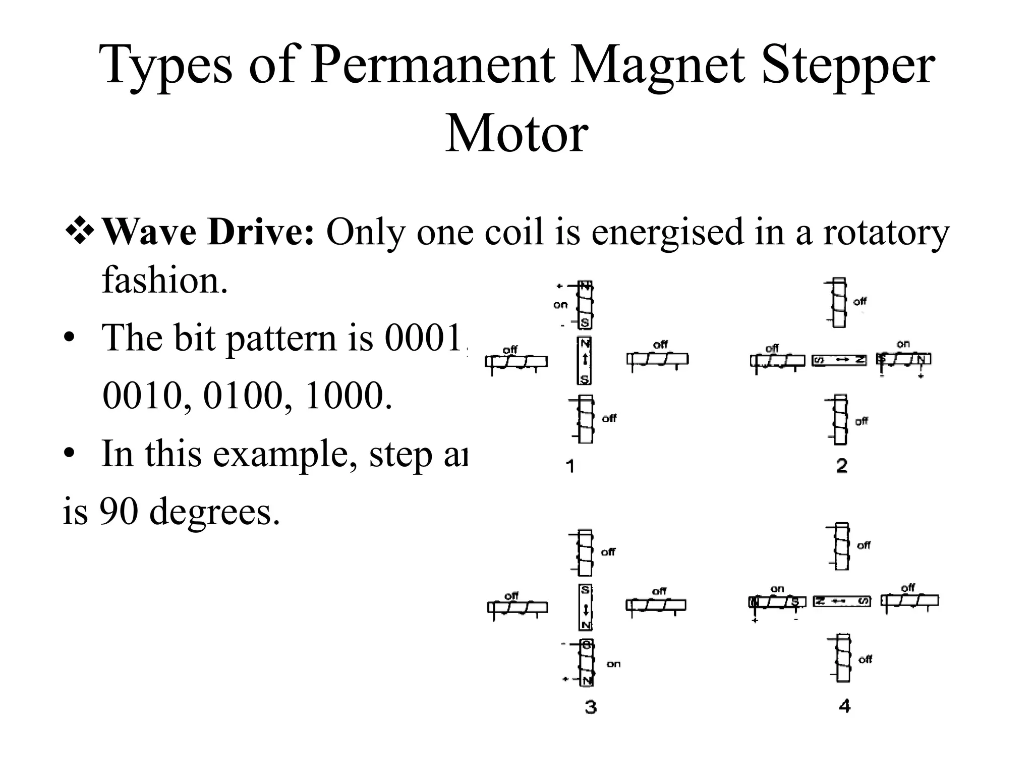
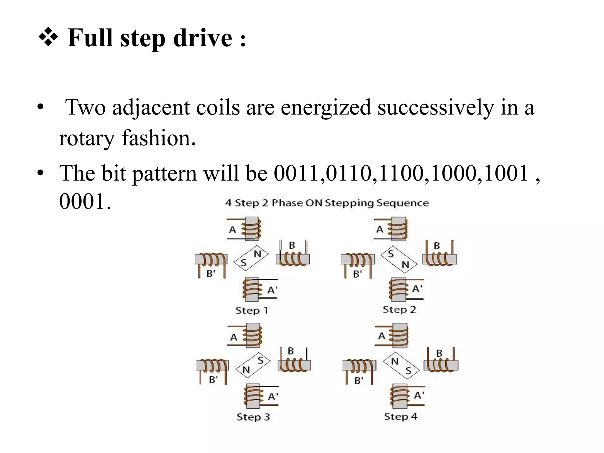
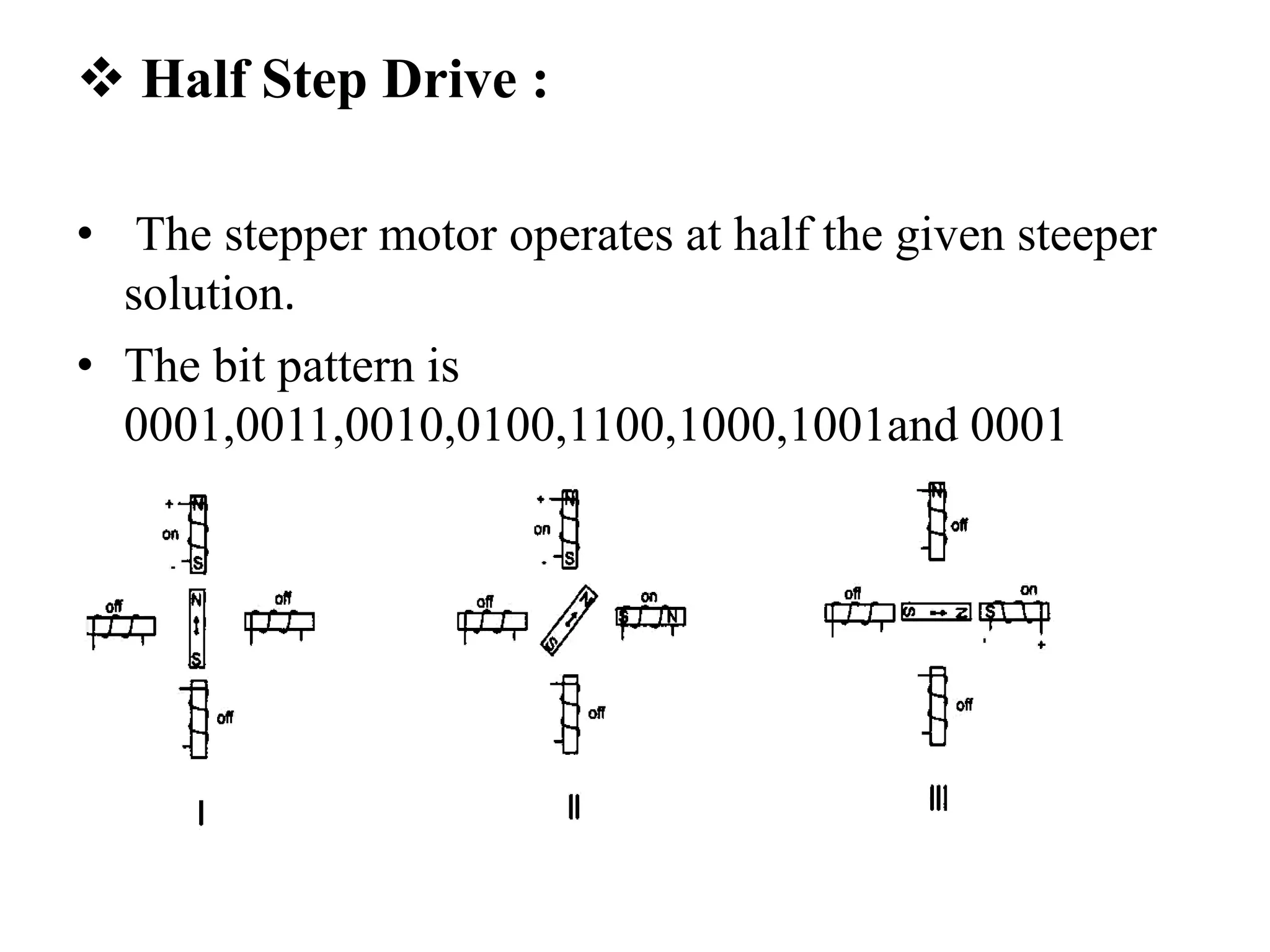
Different drive methods: wave drive, full step drive, and half step drive for stepper motors.
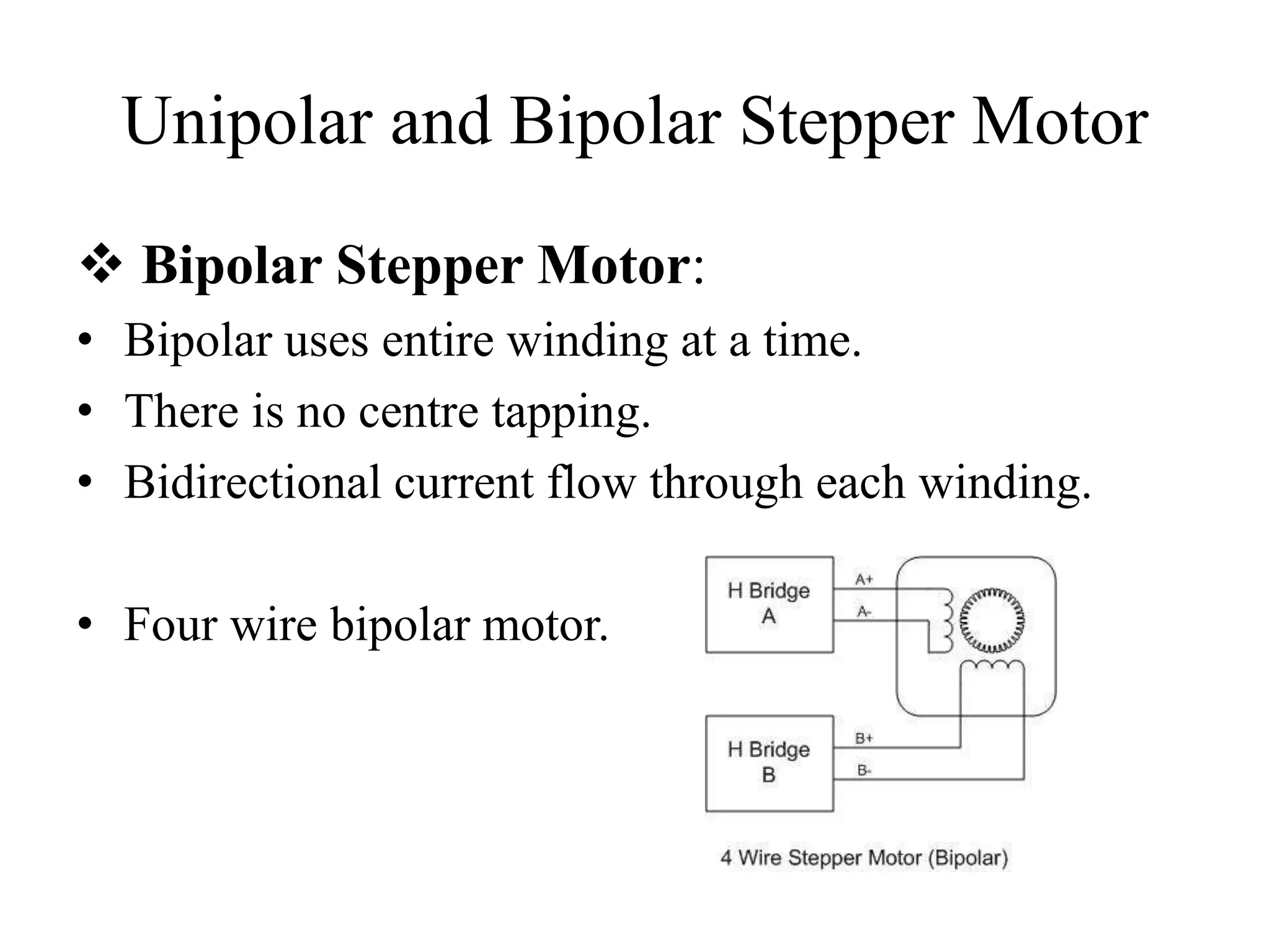
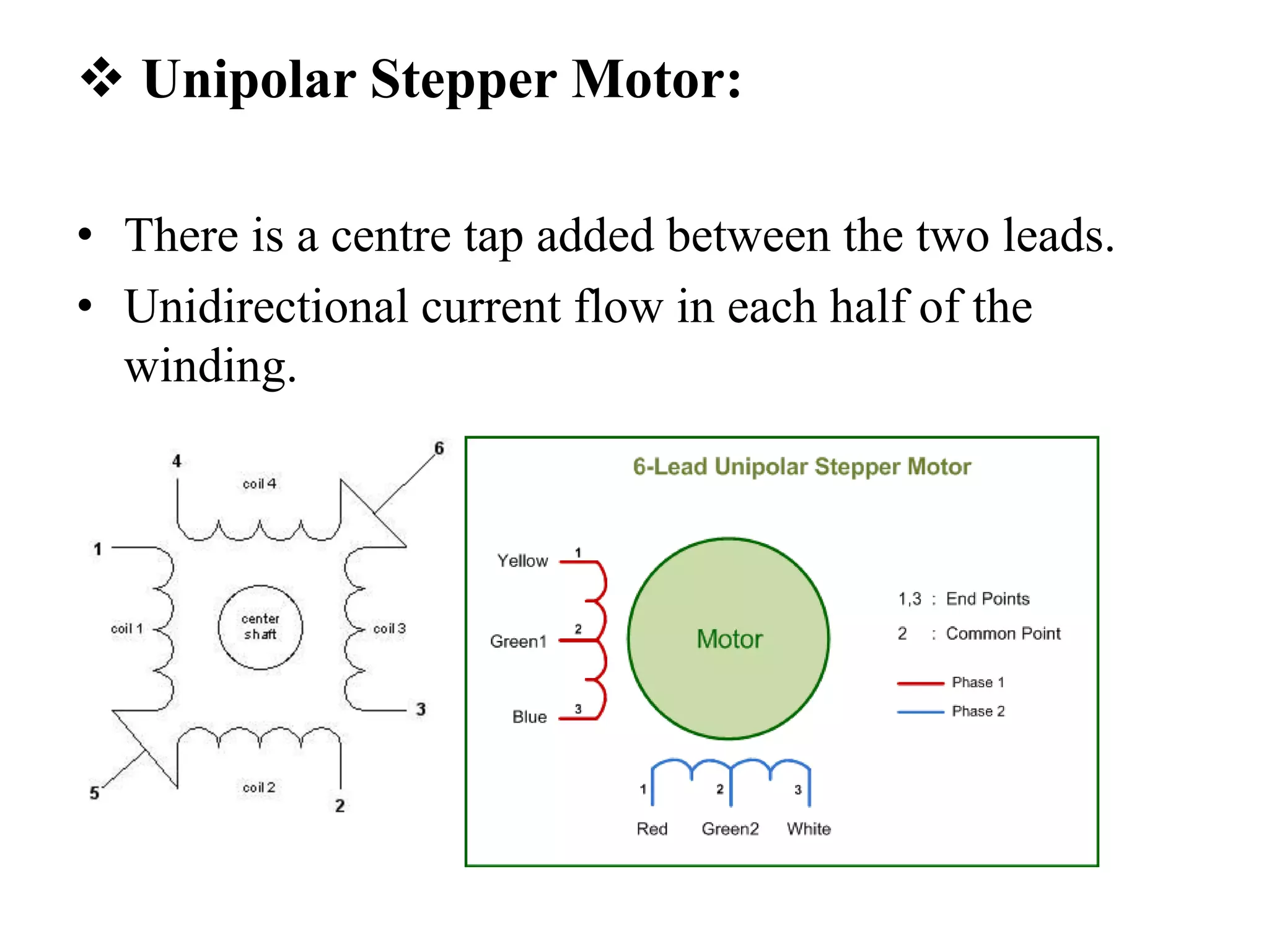
Characteristics of bipolar and unipolar stepper motors.
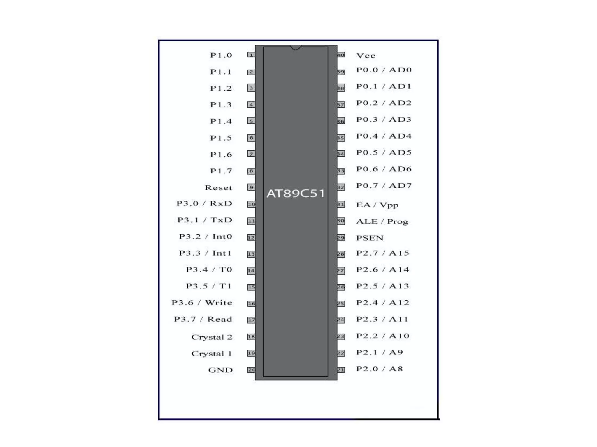
Microcontroller features, specifically AT89C51, including memory, power consumption, and functionality.
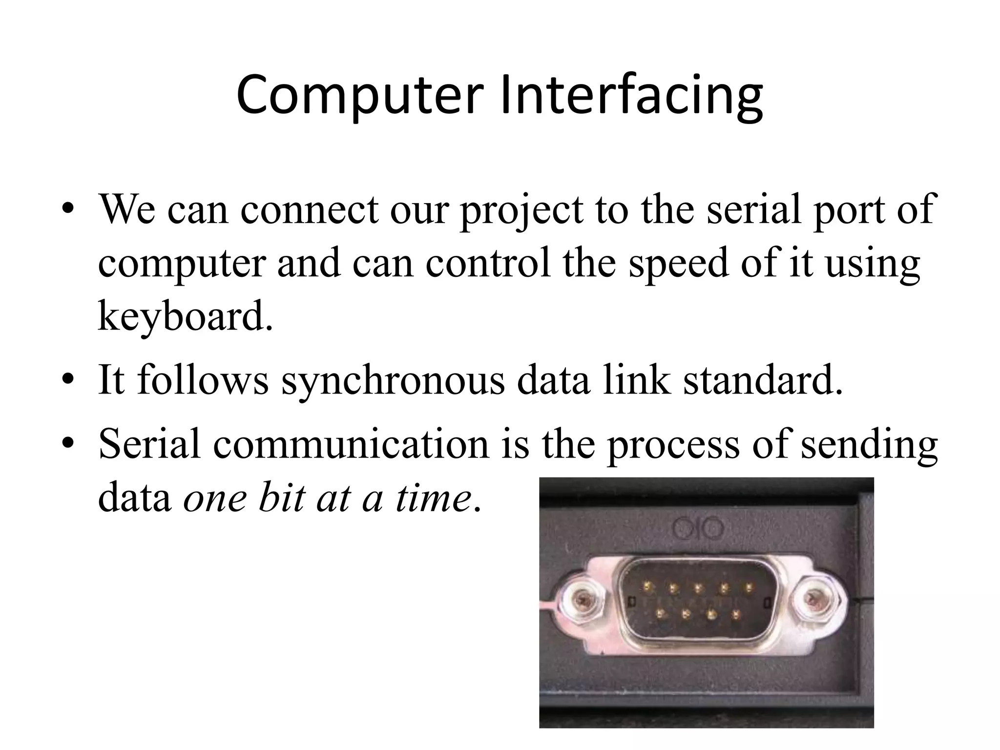
Project simulation using Proteus software, and computer interfacing capabilities for control.
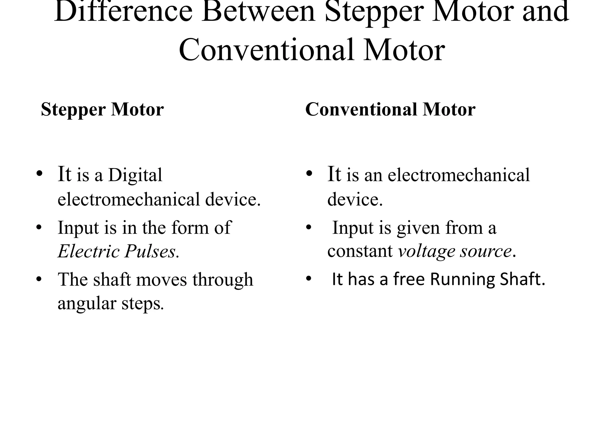
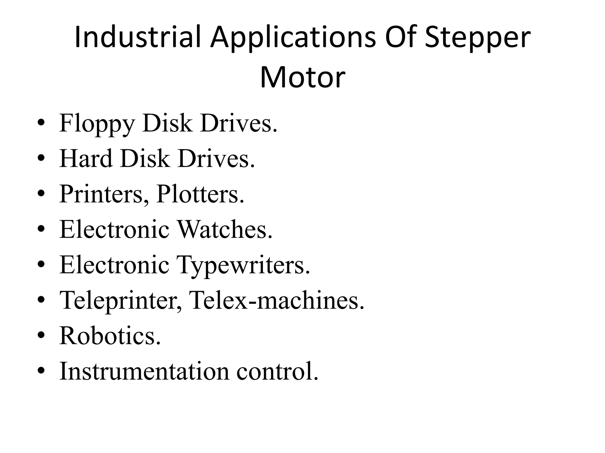
Differences between stepper motors and conventional motors, and industrial applications.
Final conclusions on project usability, implementation, cost-effectiveness, and efficiency.
Thank you note and end of the presentation.