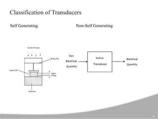
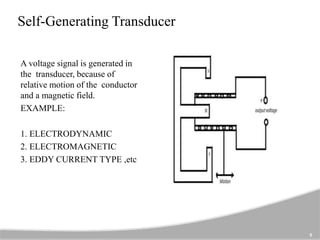
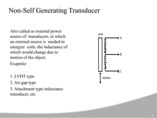
Here in this presentation we will discussing about Inductive Transducer and its working principle, a brief classification of Inductive Transducer and derivation of transducer applications
2. Introduction
Inductive transducers work on the principle of inductance
change due to any appreciable change in the quantity to be
measured i.e. measured. For example, LVDT, a kind of
inductive transducers, measures displacement in terms of
voltage difference between its two secondary voltages.
2
3. 3
In Inductive transducers, the basic principle is
that self-inductance of a single coil or the mutual
inductance between two coils is changed by a quantity
to be measured i.e. measurand. Usually, the measurand
could be a rotary or linear displacement, force,
pressure, torque, velocity, acceleration, and vibration.
5. Self-Generating Transducer
A voltage signal is generated in
the transducer, because of
relative motion of the conductor
and a magnetic field.
EXAMPLE:
1. ELECTRODYNAMIC
2. ELECTROMAGNETIC
3. EDDY CURRENT TYPE ,etc
5
6. Non-Self Generating Transducer
Also called as external power
source of transducers, in which
an external source is needed to
energize coils, the inductance of
which would change due to
motion of the object.
Exapmle:
1. LVDT type
2. Air gap type
3. Attachment type inductance
transducer, etc.
6
8. Main Working Principle
The working principle of an inductive transducer is the magnetic material’s
induction. Just like the electrical conductor’s resistance, it depends on various
factors. The magnetic material’s induction can depend on different variables like
the twists of the coil over the material, the magnetic material’s size, & the flux’s
permeability.
The magnetic materials are used in the transducers in the path of flux. There is
some air gap between them. The change in the circuit inductance can be occurred
due to the air gap change. In most of these transducers, it is mainly used to work
the instrument properly. The inductive transducer uses three working principles
which include the following.
8
9. 9
Self Inductance Change :
• We know that the coil’s self-inductance can be derived by
L = N2/R
‘R’ is the magnetic circuit’s reluctance
• The reluctance ‘R’ can be derived by the following equation
R = l/µA
• Thus, inductance equation can become like the following
L = N2 µA/l
Where
• A = It is the Coil’s cross-sectional area
• l = Coil’s length
• µ = Permeability
10. 10
• We know that geometric form factor G = A/l, then the inductance equation
will become like the following.
L = N2 µG
Eddy Current Production:
Whenever a conducting shield is located close to a coil carrying AC (alternating
current), then the current flow can be induced within the shield which is known as
“EDDY CURRENT”. This kind of principle is used in inductive transducers.
When a conducting plate is arranged near to a coil carrying AC then eddy currents
will be generated within the plate. The plate which carries eddy current will
generates their own magnetic field which works against plate magnetic field. So
the magnetic flux will be reduced.
11. Inductive Transducer Applications
11
The application of these transducers finds in proximity sensors to measure
position, touchpads, dynamic motion, etc.
Mostly these transducers are used for detecting the kind of metal, to find miss
lost parts otherwise counts the objects.
These transducers are also applicable for detecting the movement of the
apparatus which include belt conveyor and bucket elevator etc..
12. Inductive Transducer
12
Advantages:
• The responsivity of this transducer is high.
• Load effects will be reduced.
• Strong against ecological quantities.
Disadvantages:
• The operating range will be reduced due to side effects.
• The working temperature should be under the Curie temperature.
• Sensitive to the magnetic field.