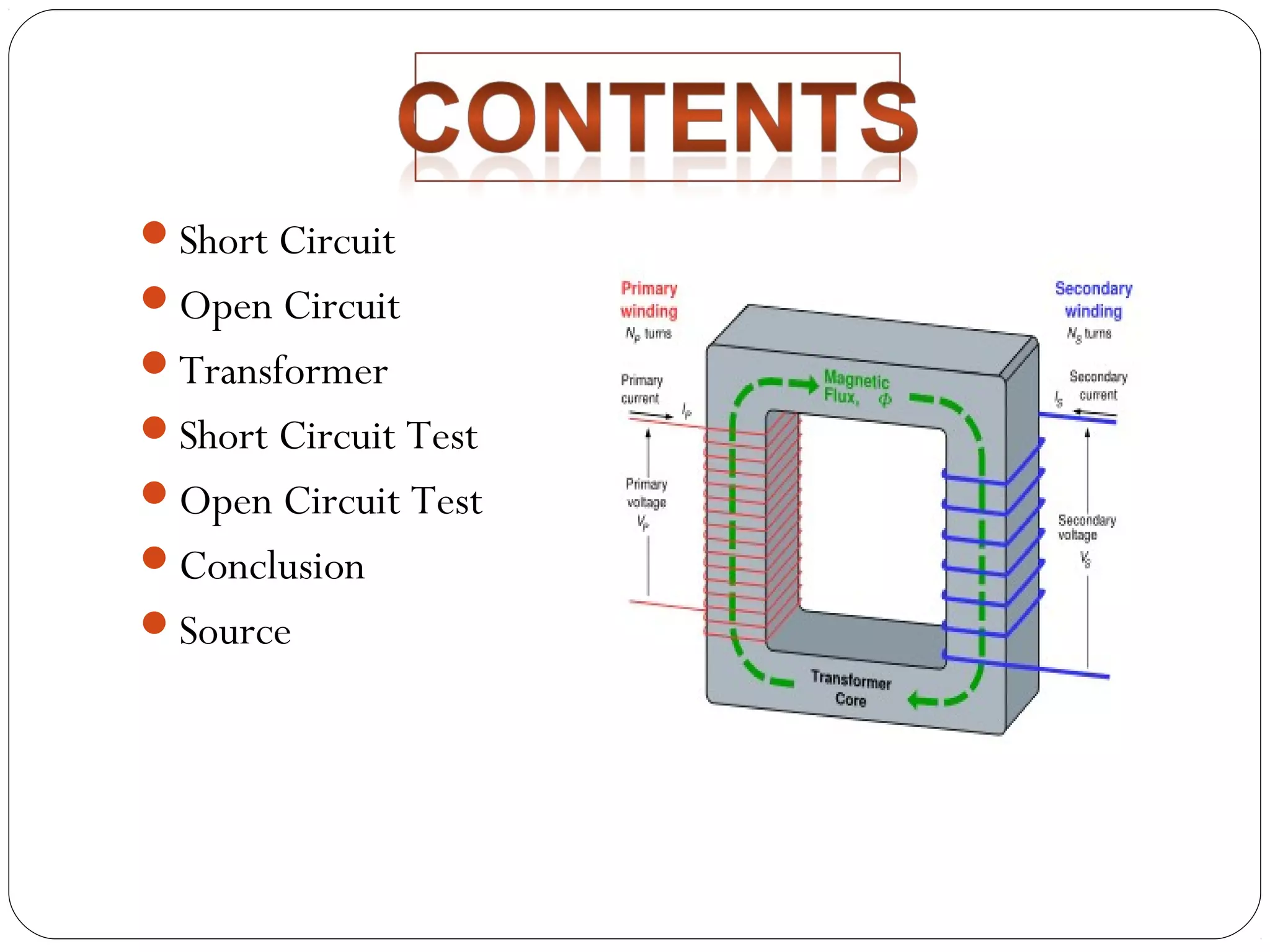
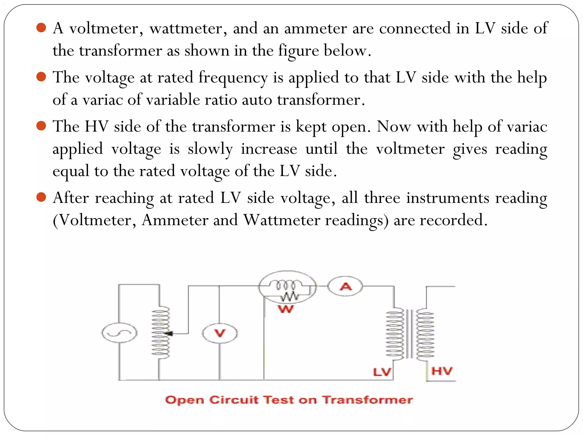
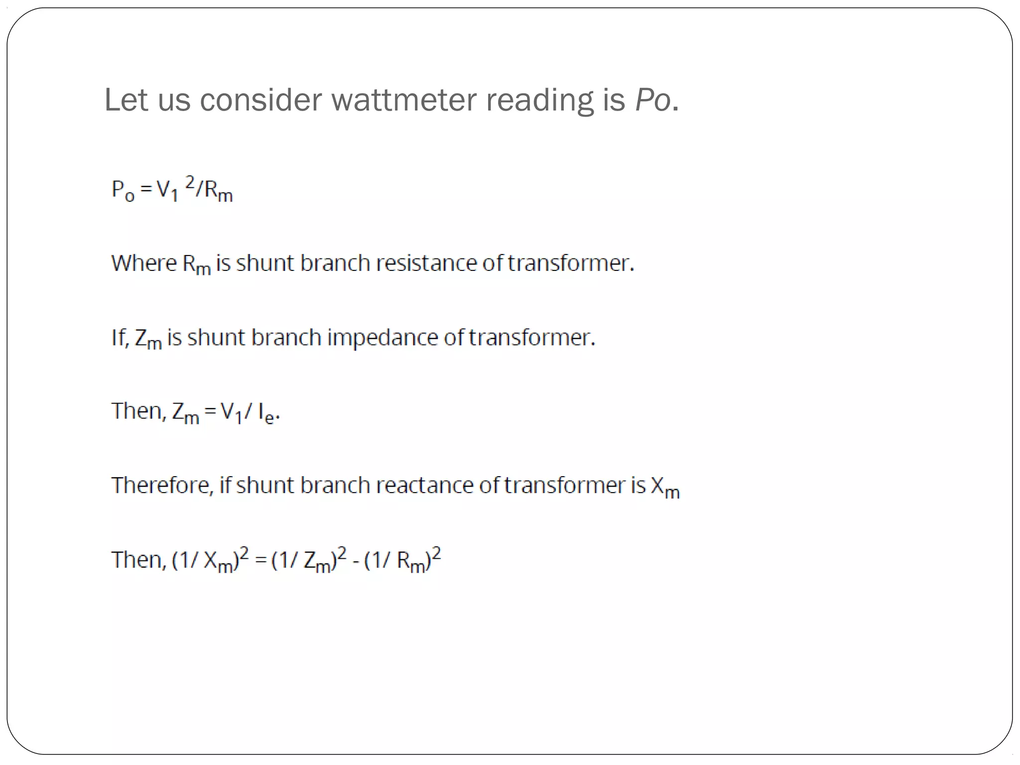
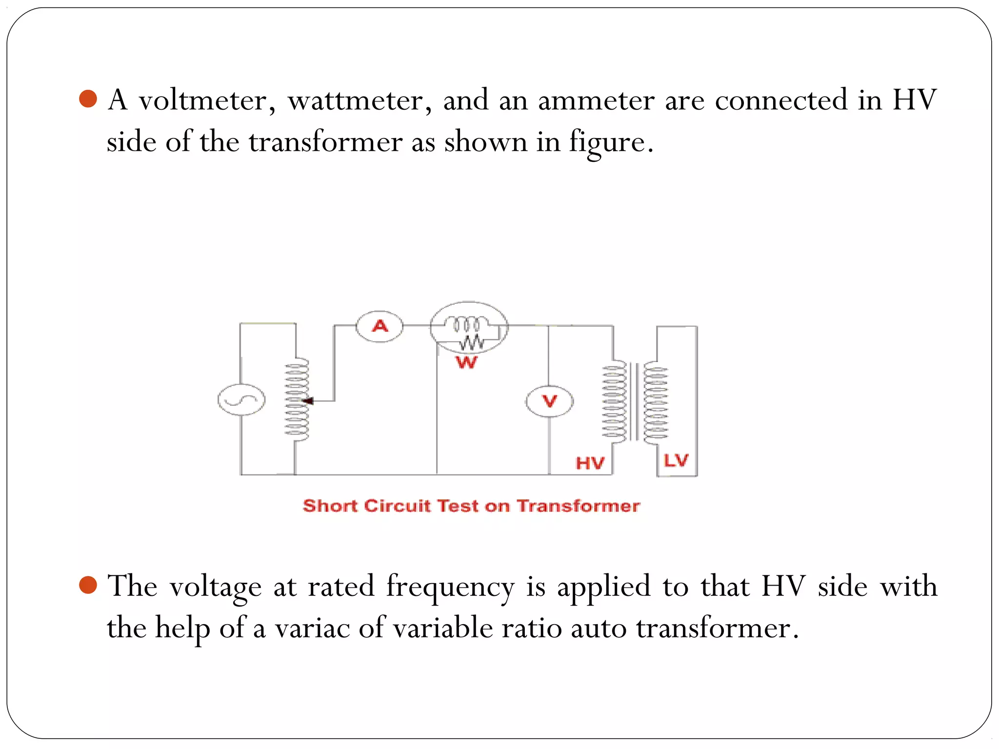
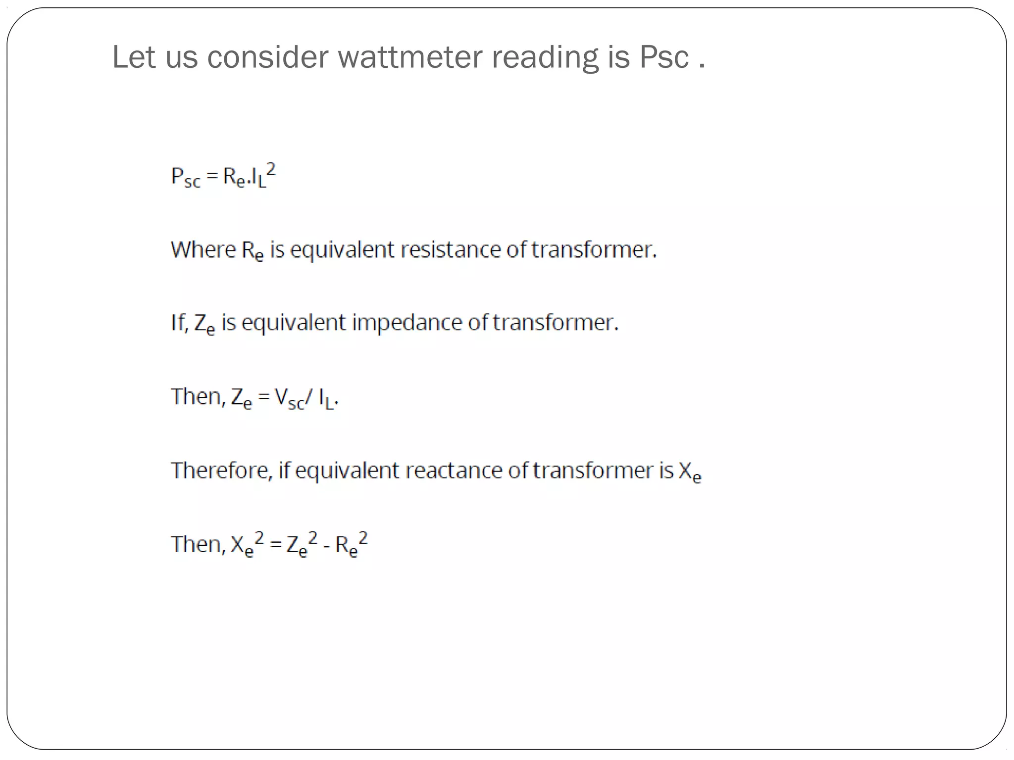
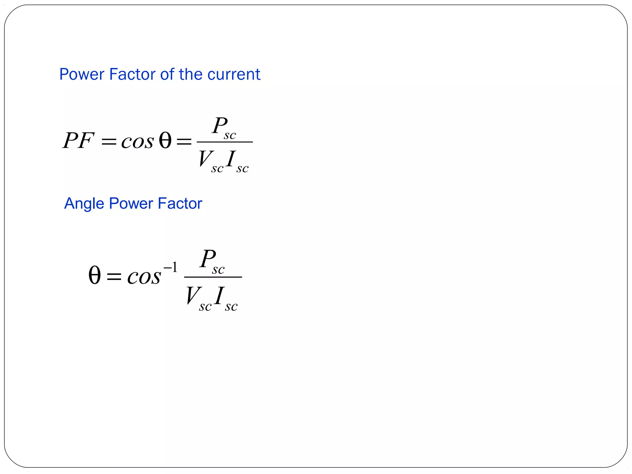
This document discusses short circuits, open circuits, and transformer tests. It explains that a short circuit allows current along an unintended path with little resistance, while an open circuit lacks a complete path for current flow. Transformer tests include open circuit and short circuit tests. The open circuit test determines core losses and shunt branch parameters, while the short circuit test determines copper losses and approximate circuit parameters. Instruments are connected and measurements recorded to evaluate losses and parameters from the tests.
To understand the basic working principle of a transformer.
To obtain the equivalent circuit parameters from Open circuit and Short circuit tests, and to estimate efficiency & regulation at various loads.
It’s a power electronics project. It is able to give output voltage(DC) more and less than input voltage as per requirement.
We can generate variable DC voltage which is less than input, but, the special things about this converter is, it has capability to produce variable DC voltage as high as twice the input voltage.
We have specially designed and manufactured inductor for this project.
Breaking,Types of Electrical Braking system, Regenerative Braking, Plugging ...Waqas Afzal
Why Breaking?
Requirements for Braking
Types of Electrical Braking system
Regenerative Braking.
Plugging type braking.
Dynamic braking.
Breaking implementations at DC Motor and AC Motor
A synchronous motor is electrically identical with an alternator or AC generator.
A given alternator ( or synchronous machine) can be used as a motor, when driven electrically.
Some characteristic features of a synchronous motor are as follows:
1. It runs either at synchronous speed or not at all i.e. while running it maintains a constant speed. The only way to change its speed is to vary the supply frequency (because NS=120f/P).
2. It is not inherently self-starting. It has to be run up to synchronous (or near synchronous) speed by some means, before it can be synchronized to the supply.
3. It is capable of being operated under a wide range of power factors, both lagging and leading. Hence, it can be used for power correction purposes, in addition to supplying torque to drive loads.
Report On diode clamp three level inverterVinay Singh
three level diode clamp inverter. that converts any type of DC ( rectified, PV cell, battery etc.) to AC supply. we made by mosfet and ardiuno . in this ppt we present the Simulink model of a three-level inverter and the hardware reort of the inverter.
also discuss about other level inverter and there THD analysis, simulink model and detail. compression between another inverter.
Introduction to feedback (block diagram and types of feedback) , Analysis at middle, low and high frequency of multi-stage amplifier with RC coupling and direct coupling, cascade amplifiers-Darlington Pair.
OPEN CIRCUIT AND SHORT CIRCUIT TEST OF SINGLE PHASE TRANSFORMER|DAY7| BASIC E...Prasant Kumar
#Open_circuit_short_circuit_test of single phase transformer
#OC_SC_TEST OF TRANSFORMER
#Core loss and copper loss test of single phase transformer.
After going through this session you will be able to answer the following questions.
• Which parameters are obtained from O.C test?
• Which parameters are obtained from S.C test?
• What percentage of rated voltage is needed to be applied to carry out O.C test?
• What percentage of rated voltage is needed to be applied to carry out S.C test?
• From which side of a large transformer, would you like to carry out O.C test?
• From which side of a large transformer, would you like to carry out S.C test?
Aim of conduction transformer Open Circuit & Short Circuit test
To predict its performance without actual loading.
Determination of equivalent circuit parameters
To determine parameters of a transformer like voltage regulation and efficiency
Open circuit test is carried out to determine core loss and shunt parameters.
Open circuit test is carried out at rated voltage and rated frequency . During this test, rated flux is produced in the core .
To carry out open circuit test rated voltage at rated frequency is applied to LV side of the transformer and HV side is left opened as shown in the circuit diagram.
HV side is left opened because it is easier to arrange rated voltage supply on LV side because no load current which is quite small about 2 to 5% of the rated current.
Metering instrument connected at LV side are economical & always safer to work.
The voltmeter, ammeter and the wattmeter readings are taken and suppose they are Voc , Io and Poc respectively.
Strictly speaking the wattmeter will record the core loss as well as the LV winding copper loss. But the winding copper loss is very small compared to the core loss as the flux in the core is rated.
An A.C. device used to change high voltage low current A.C. into low voltage high current A.C. and vice-versa without changing the frequency
In brief,
1. Transfers electric power from one circuit to another
2. It does so without a change of frequency
3. It accomplishes this by electromagnetic induction
4. Where the two electric circuits are in mutual inductive influence of each other.
A transformer is a static electrical device that transfers electrical energy between two or more circuits. A varying current in one coil of the transformer produces a varying magnetic flux, which, in turn, induces a varying electromotive force across a second coil wound around the same core. Electrical energy can be transferred between the two coils, without a metallic connection between the two circuits. Faraday's law of induction discovered in 1831 described the induced voltage effect in any coil due to changing magnetic flux encircled by the coil
O.C & S.C Test, Sumpner or back to back Test, Condition for maximum efficienc...Abhishek Choksi
Sub: DC Machines and Transformer (2130904)
Active Learning Assignment
Topic: O.C & S.C Test, Sumpner or back to back Test, Condition for maximum efficiency, All day Efficiency
2. Short Circuit
Open Circuit
Transformer
Short Circuit Test
Open Circuit Test
Conclusion
Source
3. A short circuit is an electrical circuit that allows a current to
travel along an unintended path, often where essentially no
(or a very low) electrical impedance is encountered.
In circuit analysis a short circuit is a connection between two
nodes that forces them to be at the same voltage.
In an ideal short circuit, this means there is no resistance and
no voltage drop across the short.
In real circuits, the result is a connection with almost no
resistance. In such a case, the current that flows is limited by
the rest of the circuit.
4. An electrical circuit is an "open circuit" if it lacks a complete
path between the terminals of its power source; in other words,
if no true "circuit" currently exists, because for instance a
power switch is turned off.
The electrical opposite of a short circuit is an "open circuit",
which is an infinite resistance between two nodes.
The open circuit test, or "no-load test", is one of the methods
used in electrical engineering to determine the no load
impedance in the excitation branch of a transformer.
.
5.
6.
7. A transformer is a static electrical device that transfers energy by
inductive coupling between its winding circuits.
A varying current in the primary winding creates a varying magnetic flux
in the transformer's core and thus a varying magnetic flux through the
secondary winding. This varying magnetic flux induces a varying
electromotive force (emf) or voltage in the secondary winding.
In electrical engineering, two conductors are referred to as mutual-inductively
coupled or magnetically coupled when they are configured
such that change in current flow through one wire induces a voltage
across the ends of the other wire through electromagnetic induction. The
amount of inductive coupling between two conductors is measured by
their mutual inductance.
8.
9.
10. These two tests are performed on a transformer to determine:-
(i) equivalent circuit of transformer
(ii) voltage regulation of transformer
(iii) efficiency of transformer.
The power required for these Open Circuit test and Short
Circuit test on transformer is equal to the power loss occurring
in the transformer.
11.
12. A voltmeter, wattmeter, and an ammeter are connected in LV side of
the transformer as shown in the figure below.
The voltage at rated frequency is applied to that LV side with the help
of a variac of variable ratio auto transformer.
The HV side of the transformer is kept open. Now with help of variac
applied voltage is slowly increase until the voltmeter gives reading
equal to the rated voltage of the LV side.
After reaching at rated LV side voltage, all three instruments reading
(Voltmeter, Ammeter and Wattmeter readings) are recorded.
13. The ammeter reading gives the no load current Ie.
As no load current Ie is quite small compared to rated current of the
transformer, the voltage drops due to this electric current then can
be taken as negligible.
Since, voltmeter reading V can be considered equal to secondary
induced voltage of the transformer. The input power during test is
indicated by watt-meter reading.
As the transformer is open circuited, there is no output hence the
input power here consists of core losses in transformer and copper
loss in transformer during no load condition.
The no load current in the transformer is quite small compared to
full load current so copper loss due to the small no load current can
be neglected.
Hence the wattmeter reading can be taken as equal to core losses in
transformer.
15. These values are referred to the LV side of transformer as
because the test is conduced on LV side of transformer.
These values could easily be referred to HV side by
multiplying these values with square of transformation ratio.
Therefore it is seen that the open circuit test on transformer
is used to determine core losses in transformer and
parameters of shunt branch of the equivalent circuit of
transformer.
16. Open circuit Power Factor
PF = cos q = P
oc
V I
oc oc
Open circuit Power Factor Angle
q = cos-1 P
oc
V I
oc oc
17.
18. A voltmeter, wattmeter, and an ammeter are connected in HV
side of the transformer as shown in figure.
The voltage at rated frequency is applied to that HV side with
the help of a variac of variable ratio auto transformer.
19. The LV side of the transformer is short circuited . Now with
help of variac applied voltage is slowly increase until the
ammeter gives reading equal to the rated current of the HV
side
After reaching at rated current of HV side, all three
instruments reading (Voltmeter, Ammeter and Watt-meter
readings) are recorded
The ammeter reading gives the primary equivalent of full load
current IL.
As the voltage, applied for full load current in short circuit
test on transformer, is quite small compared to rated primary
voltage of the transformer, the core losses in transformer can
be taken as negligible here.
20. Let’s, voltmeter reading is VSC . The input power during test is
indicated by watt-meter reading.
As the transformer is short circuited, there is no output hence
the input power here consists of copper losses in transformer
Since, the applied voltage Vsc is short circuit voltage in the
transformer and hence it is quite small compared to rated
voltage so core loss due to the small applied voltage can be
neglected.
Hence the wattmeter reading can be taken as equal to copper
losses in transformer.
22. These values are referred to the HV side of transformer as
because the test is conduced on HV side of transformer.
These values could easily be referred to LV side by dividing
these values with square of transformation ratio.
Therefore it is seen that the Short Circuit test on transformer is
used to determine copper loss in transformer at full load and
parameters of approximate equivalent circuit of transformer.
23. Power Factor of the current
PF = cosq = P
sc
V I
sc sc
Angle Power Factor
q = cos-1 P
sc
V I
sc sc
24.
25. the open circuit test on transformer is used to determine
core losses in transformer and parameters of shunt branch of
the equivalent circuit of transformer.
the Short Circuit test on transformer is used to determine
copper loss in transformer at full load and parameters of
approximate equivalent circuit of transformer.