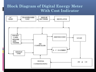
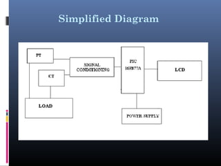
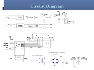
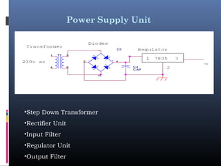
This document describes the design of a digital energy meter with a cost indicator. It has three main parts: a power sensing unit, a power and cost calculation unit, and a display unit using LCD. It measures power consumption and calculates the energy used in kW/h and the corresponding cost based on the tariff rates stored in the microcontroller. The values are displayed on the LCD. It is designed using components like a PIC microcontroller, current and potential transformers, and an LCD for display. The circuit uses a power supply unit consisting of a step-down transformer, rectifier, filters and regulators to provide the necessary power.
2. ABTRACT
To calculate Power utilization, cost in a home and display its
values, and also implement the prepaid card system using
“Embedded system technology” and also display using “LCD”
It has three separate parts
1. Power sensing part
2. Power and Cost Calculation Part
3. Displaying part by using “LCD” display control
3. Prepaid Cards
We are using one prepaid card and card reader. The card
reader is read the credit values from prepaid card, this
value is stored in controller. Sensors sensed the power
the sensing values are given to micro controller . When
ever the utilization cost values is equal to prepaid
amount, the controller turnoff the power supply
4. Embedded Systems
An embedded system is a microcontroller-based, software
driven, reliable, real-time control system
Embedded System is a combination of hardware and software
used to achieve a single specific task.
Embedded systems are computer systems that monitor,
respond to or control an external environment.
Environment connected to systems through sensors, actuators
and other I/O interfaces.
Embedded system must meet timing & other constraints
imposed on it
5. Relays
A relay is usually an electromechanical device that is actuated
by an electrical current.
Relays are used in a wide variety of applications throughout
industry, such as in telephone exchanges, digital computers
and automation systems.
Input may be electrical and output directly mechanical or vice
versa.
Relays are like remote control switches and are used in many
applications because of their relative simplicity, long life, and
proven high reliability.
6. Micro Controller
The micro-controller is a chip, which has a computer
processor with all its support function, memory (both
program storage and RAM) and I/O built in to the device.
Micro-controllers getting faster, smaller and more power
efficient they are also getting more and more features.
Micro controllers programmers can be built very cheaply or
even built in to the final application circuit eliminating the
need for a separate circuit.
7. Advantages Of Using a
Microcontroller Over Microprocessor
A designer will use a microcontroller to
Gather input from various sensors
Process this input into a set of actions
Use the output mechanisms on the Microcontroller to do
something useful
RAM and ROM are inbuilt in the MC.
Cheap compared to MP.
Multi machine control is possible simultaneously.
Examples: 8051 (ATMAL), PIC (Microchip), Motorola(Motorola),
ARM Processor
11. LCD Display
• Liquid crystal display (LCD) has material which combines the
properties of both liquid and crystals. They have a temperature
range within which the molecules are almost as mobile as they
would be in a liquid, but are grouped together in an order form
similar to a crystal.
• Each pixel of an LCD typically consists of a layer
of molecules aligned between two transparent electrode
• LCDs with a small number of segments, such as those used
in digital watches and pocket calculator, have individual
electrical contacts for each segment.
12. Control lines from the microcontroller.
Enable (E) This line allows access to the display through R/W and RS lines. When this
line is low, the LCD is disabled and ignores signals from R/W and RS. When
(E) line is high, the LCD checks the state of the two control lines and
responds accordingly.
Read/Write
(R/W)
This line determines the direction of data between the LCD and
microcontroller. When it is low, data is written to the LCD. When it is high,
data is read from the LCD.
Register
select (RS)
With the help of this line, the LCD interprets the type of data on data lines.
When it is low, an instruction is being written to the LCD. When it is high, a
character is being written to the LCD.
13. ENERGY METER
An electricity meter or energy meter is a device that measures
the amount of electric energy consumed by a residance,business
or an electrically powered device.
Electricity meters are typically calibrated in billing units, the
most common one being the kilowatt hour.
There are three types of meter in common use in households.
1.Standard meters
2.Variable rate meters
3.Prepayment meters
•
14. TYPES OF ENERGY METERS
Standard meters:
A standard meter is a basic electromechanical induction meter measures
electricity consumption in terms of kilowatt-hours the amount of energy used
by a load of one kilowatt over the period of one hour.
Meter is installed all electricity units are charged at the same rate 24 hours
a day.
Variable rate meters:
Referred to as “economy 7″ meters as they are used for the economy 7 tariffs
Suppliers offer variable rate meters operate on the same principle as
standard meters they give two readings one for daytime electricity usage
and one for night-time electricity usage.
15. Cont…
This allows your supplier to charge you a different (usually cheaper)
rate for electricity used at night time under the economy 7 tariff.
Prepayment meters:
Prepayment meters usually accept tokens or cards that can be bought
or topped up respectively.
Customer stops paying for electricity, the electricity supply will be cut
off by a relay fitted into the meter.
The advantage of this kind of meter is that you can budget for how
much electricity you use by paying for it before you use it.
18. Block Description
The major components of this project are PIC microcontroller, CT & PT
and LCD display
The main process of this project is to measure the High voltage and
high current of the major equipments, this is done through CT & PT.
These parameters are reads into controller through signal conditioning
unit and first the controller converts into digital unit inbuilt ADC
The power supply unit maintains the power as necessary for the entire
project using regulator, 7812 for 12v supply and 7805 for 5v .
After getting the digital value of current and voltage controller
calculates parameters of power consumption, number of units and cost
of energy consumed.
19. Multiple tariff (variable rate) meters
Electricity retailers may wish to charge customers different
tariffs at different times of the day. This is because there is
generally a surplus of electrical generation capacity at times
of low demand , such as during the night (see supply and
demand).
Some multiple tariff meters use different tariffs for different
amounts of demand. These are usually industrial meters.
21. Circuit Description
Power supply unit consists of Step down transformer, Rectifier,
Input filter, Regulator unit, Output filter.
The Step down Transformer is used to step down the main supply
voltage from 230V AC to lower value.
The Rectifier circuit is used to convert the AC voltage into its
corresponding DC voltage.
There are Half-Wave, Full-Wave and bridge Rectifiers available for
this specific function
The most important and simple device used in Rectifier circuit is
the diode.
The circuit used for removing the ripples is called Filter circuit.
22. Power Supply Unit
•Step Down Transformer
•Rectifier Unit
•Input Filter
•Regulator Unit
•Output Filter
23. Calculation of Power, Energy and Cost of
Energy
Electricity bill will be charged on per unit basis.
Cost of one Kilowatt-hour (kWh)
1 Kilowatt-hour (kWh) x cost of 1 Kilowatt-hour (kWh)
1 Kilowatt-hour (kWh) x cost of one unit.
[power =voltage x ampere]
The kW is a unit of power. It is 1000 W or 1000 J/s.
Power = Energy / Time : Energy = Power × Time
If we choose to measure power in kW and time in hours,
Energy (kWh) = power (kW) × time (h)
24. Conclusion
The System “DIGITAL ENERGY METER WITH COST
INDICATOR” is developed and operated successfully in the
laboratory.
The circuit having potential and current transformers which
gives the power consumption in analog form. This is
converted to digital and the converted one is again converted
into KWH form i.e. one unit.
According to the tariff rates stored in the microcontroller,
the consumed units and cost are displayed on the LCD.
25. Future Enhancement
In future this circuit can also be used as a prepaid energy
meter using a smart type arrangement. For we want to add a
smart card reader and relay in extra. Due to this every
customer has a smart card with some credits and after
completing these credits we again go to EB and recharge the
card.
The energy meter reading can be send to the EB by
implementing small kind of SCADA system, using this the
readings can be straightly monitor by the EB.
26. References
e-book –“Complete guide to PIC microcontroller”
John Peatman- “Embedded PIC microcontroller”
Kirk Zurell- “C programming for embedded systems”
Myke Predcko- “Customizing and programming your PIC
microcontroller”
Onathan W.Valvano(2000)-“Embedded Microcomputer system”
Stan Giblisco –“Teach yourself electronics