Downloaded 221 times
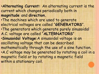
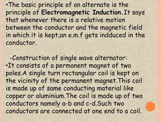
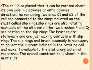
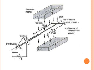
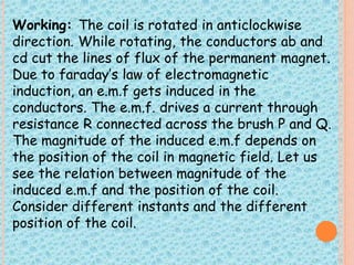
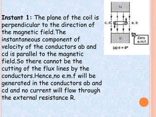
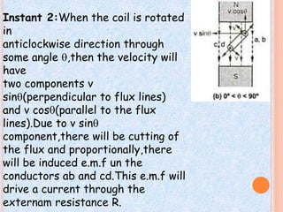
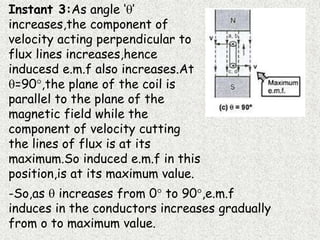
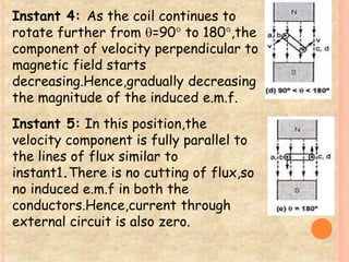
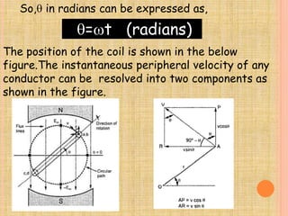
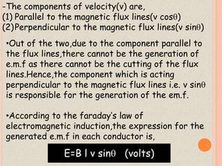


1) The document discusses the generation of alternating current using a single-turn alternator with a rotating coil within a magnetic field. 2) As the coil rotates, an alternating voltage is induced based on Faraday's law of electromagnetic induction. The magnitude of the induced voltage depends on the angle of rotation and reaches its maximum when the coil is perpendicular to the magnetic field lines. 3) The instantaneous induced voltage can be expressed as a sinusoidal function of the angle of rotation, with the maximum voltage achieved at 90° of rotation. This generates an alternating current through a load that also follows a sinusoidal pattern.


![[L2 Sambhav] Electro magnetic induction.pdf](https://cdn.slidesharecdn.com/ss_thumbnails/l2sambhavemi-231215223335-2720969b-thumbnail.jpg?width=640&height=640&fit=bounds)


![[Deck] What's New in Spark-Iceberg Integration via DSV2.pptx](https://cdn.slidesharecdn.com/ss_thumbnails/deckwhatsnewinspark-icebergintegrationviadsv2-260210005337-25955b12-thumbnail.jpg?width=640&height=640&fit=bounds)


