Downloaded 498 times


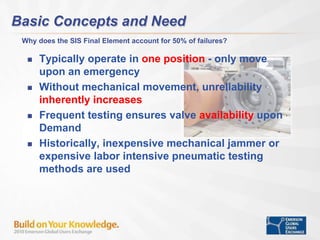
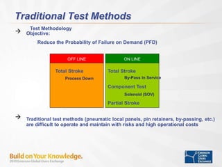


This document discusses using a digital valve controller to improve diagnostics and testing of safety instrumented system (SIS) final control elements. Traditional testing methods are difficult and costly. A digital valve controller allows for partial stroke testing online which improves reliability while reducing costs. It also enables solenoid valve health monitoring and diagnostic capabilities. Field experience from Ras Gas in Qatar demonstrated benefits like reduced labor and improved predictive maintenance through signature-based testing and continuous monitoring.


