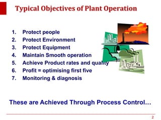
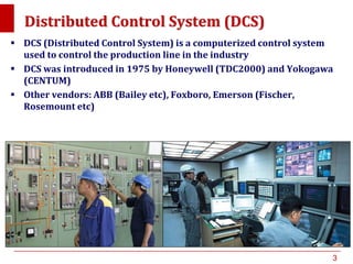
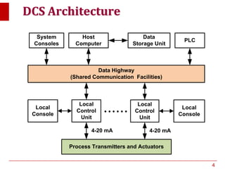
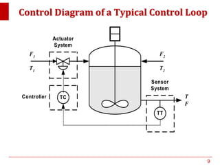
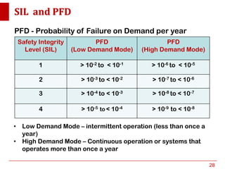
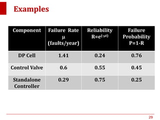
Plant Operation
Systems
DR. AA
1
Typical Objectives of Plant Operation
1. Protect people
2. Protect Environment
3. Protect Equipment
4. Maintain Smooth operation
5. Achieve Product rates and quality
6. Profit = optimising first five
7. Monitoring & diagnosis
These are Achieved Through Process Control…
2
Distributed Control System (DCS)
 DCS (Distributed Control System) is a computerized control system
used to control the production line in the industry
 DCS was introduced in 1975 by Honeywell (TDC2000) and Yokogawa
(CENTUM)
 Other vendors: ABB (Bailey etc), Foxboro, Emerson (Fischer,
Rosemount etc)
3
DCS Architecture
Process Transmitters and Actuators
Data Highway
(Shared Communication Facilities)
......
Data
Storage Unit
Host
Computer
System
Consoles
PLC
4-20 mA
Local
Console
Local
Control
Unit
4-20 mA
Local
Control
Unit
Local
Console
4
Fieldbus Technology
 Introduced 1988 but underwent many
development
 Standard IEC61158 introduced in
1999
 Based upon smart devices installed
in the field.
 Uses data highway to replace wires
for signal transfer.
 Can mix sensors, transmitters, and
control valves from different vendors
CEAG
I/O
P5001 0
... 150 bar
•Foundation Fieldbus (FF)
•Profibus (Process Field Bus)
•Others: ControlNet, P-Net, SwiftNet ,
WorldFIP, Interbus, EtherCAT, SERCODS etc
5
Fieldbus Architecture
Plant Optimization
.................
Smart
Sensors
Smart Control
Valves and
Controllers
Local
Area
Network
Smart
Sensors
Smart Control
Valves and
Controllers
Local
Area
Network
H1 Fieldbus NetworkH1 Fieldbus Network
H1 Fieldbus H1 Fieldbus
Data Storage
PLCs
High Speed Ethernet
6
PLC Architecture
Processor
Power
Supply
Data Highway
PLC Cabinet
Programming
Interface
I/O Modules
Input
Devices
Output
Devices
7
We desire independent protection layers, without common-
cause failures - Separate systems
sensors
SIS system
i/o i/o………….
sensors
Digital control system
i/o i/o………….
DCS handles controls
and alarms functions.
PLC handles SIS and
Alarms associated with SIS
Redundancy
8
Control Diagram of a Typical Control Loop
Controller
F1
T1
T
F
F2
T2
TC
Actuator
System
TT
Sensor
System
9
Sensor System
 Sensors
– Temperature, Flow, Liquid Level, Pressure, pH,
 Transmitter
10
Temperature Measurement
 Expansion Thermometer
– Liquid in Glass
– Mercury in Steel
– Bimetallic Elements
 Thermoelectric Thermometers (Thermocouple)
– Type J, K, T, R, S, ...
 Resistance Thermometers
– Thermister
– Resistance Thermal Detector (RTD), e.g. Pt100
 Radiation Thermometers (Optical Pyrometers)
11
Pressure Measurement
 Direct pressure Measurement
– manometer
 Indirect Pressure Measurement
– Bourdon Tubes, Bellows, Diaphragms
 Electrical Pressure Transducers
– Capacitive, Resistive, Inductive
 Other Pressure Transducers
– Force Balance, DP Cell, Piezoelectric Transducer
12
Flow Measurement
 Point Velocity Measurement
– Pitot Tube, Hot Wire Anemometer, Transit Time
Velocimeters
 Gross Volume Flow Measurement
– Venturi Tube, Orifice Plate, Nozzle, Dall Tube,
Rotameter, Turbine Meter, Positive Displacement
Meters (piston, gear etc)
 Gross Mass Flow measurement
– Direct Method - Momentum Type, Thermal Type
– Indirect Method - calculate density & pressure etc.
13
Liquid Level
 Dipstick, Sight glass, Float
 Diaphragm
 Load Cell
 Manometer, Direct Pressure, Differential
Pressure
 Capacitive Probe
 Ultrasonic
14
Chemical Composition
 Refractive Index
 Spectroscopy
– IR/UV/Visible Spectrophotometer, Mass
Spectrophotometer, Atomic Absorption
Spectrophotometer
 Chromatography
– Gas Chromatography, Liquid Chromatography
15
Actuators System
 On/Off
– On-Off Valves
– Pumps (motor)
 Variable position
– Control Valves
– Variable speed pump
• DC motor
• 3-phase motor
• Turbine drive
16
Control valve
17
Butterfly valve
18
Actuator
19
Valve with actuator
& positioner
20
Why are some valves Fail-Opened, While
Others Fail-Closed
21
Typical response of Control Valves
A. Quick-Opening
B. Linear
C. Square-root
D. Equal Percentage
Percentage of
Maximum flow
Percentage of Stem Travel
A
B
D
C
Why do we need different shapes of plugs in the
control valves ?
22
Motor Speed Control
 DC Motor Speed Control
– Adjust the power of motor by varying current or
voltage
 AC Motor Speed Control (3 Phase Motor)
– Adjust the power of motor by varying the frequency of
the AC cycles
 Steam Driven Turbine
– Adjust the turbine speed to adjust the pumping rates
23
Safety Features
 Alarms & Enunciators
 Interlocks
– To isolate the impact of process failures from one
section from another
 Rupture Disks, Pressure Relieve Valves, etc
24
Controller System
 Stand Alone Controller
 Supervisory Control
 DCS
25
How Reliable are Those Instruments?
 Reliability can be estimated using the
following equation
t
eR 

Here R is reliability,  is the annual failure
frequency (failure/year) and t is time (year)
t
eRp 
 11
 The failure probability can then be estimated:
Here p is the annual probability of failure
26
Safety Integrity Level (SIL)
 A SIL is a measure of safety system performance, in
terms of probability of failure on demand (PFD). The
higher the SIL is, the more reliable or effective the
system is.
 Every Safety Instrumented Function (SIF) has a SIL
classification guided by the IEC 61508 standard
 ANSI/ISA S84.01 and IEC 61508 require that companies
assign a target SIL for any new or retrofitted SIS.
 Three sector specific standards have been released
using the IEC 61508 framework, IEC 61511 (process),
IEC 61513 (nuclear) and IEC 62061 (manufacturing).
27
SIL and PFD
Safety Integrity
Level (SIL)
PFD
(Low Demand Mode)
PFD
(High Demand Mode)
1 > 10-2 to < 10-1 > 10-6 to < 10-5
2 > 10-3 to < 10-2 > 10-7 to < 10-6
3 > 10-4 to < 10-3 > 10-8 to < 10-7
4 > 10-5 to < 10-4 > 10-9 to < 10-8
PFD - Probability of Failure on Demand per year
• Low Demand Mode – intermittent operation (less than once a
year)
• High Demand Mode – Continuous operation or systems that
operates more than once a year
28
Examples
Component Failure Rate

(faults/year)
Reliability
R=e(-t)
Failure
Probability
P=1-R
DP Cell 1.41 0.24 0.76
Control Valve 0.6 0.55 0.45
Standalone
Controller
0.29 0.75 0.25
29
How to Assign SIL Level?
 PFD requirement typically determine by the
PHA Team. Based on this, required SIL is
identified.
 There are various methodology available e.g.
HSE Research report no 216 as well as others
30
Typical Product SIL (General Motors)
Product SIL Suitability
Level
FL4000 Flame Detector (Multi-
Spectral IR)
3
FL3111 Flame Detector (UV) 2
S100C Combustible gas detector 3
Field Mounted Display 2
TA102A Controller 2
31
End of Topic 1.3
32

Plant Operation System

  • 1.
  • 2.
    Typical Objectives ofPlant Operation 1. Protect people 2. Protect Environment 3. Protect Equipment 4. Maintain Smooth operation 5. Achieve Product rates and quality 6. Profit = optimising first five 7. Monitoring & diagnosis These are Achieved Through Process Control… 2
  • 3.
    Distributed Control System(DCS)  DCS (Distributed Control System) is a computerized control system used to control the production line in the industry  DCS was introduced in 1975 by Honeywell (TDC2000) and Yokogawa (CENTUM)  Other vendors: ABB (Bailey etc), Foxboro, Emerson (Fischer, Rosemount etc) 3
  • 4.
    DCS Architecture Process Transmittersand Actuators Data Highway (Shared Communication Facilities) ...... Data Storage Unit Host Computer System Consoles PLC 4-20 mA Local Console Local Control Unit 4-20 mA Local Control Unit Local Console 4
  • 5.
    Fieldbus Technology  Introduced1988 but underwent many development  Standard IEC61158 introduced in 1999  Based upon smart devices installed in the field.  Uses data highway to replace wires for signal transfer.  Can mix sensors, transmitters, and control valves from different vendors CEAG I/O P5001 0 ... 150 bar •Foundation Fieldbus (FF) •Profibus (Process Field Bus) •Others: ControlNet, P-Net, SwiftNet , WorldFIP, Interbus, EtherCAT, SERCODS etc 5
  • 6.
    Fieldbus Architecture Plant Optimization ................. Smart Sensors SmartControl Valves and Controllers Local Area Network Smart Sensors Smart Control Valves and Controllers Local Area Network H1 Fieldbus NetworkH1 Fieldbus Network H1 Fieldbus H1 Fieldbus Data Storage PLCs High Speed Ethernet 6
  • 7.
    PLC Architecture Processor Power Supply Data Highway PLCCabinet Programming Interface I/O Modules Input Devices Output Devices 7
  • 8.
    We desire independentprotection layers, without common- cause failures - Separate systems sensors SIS system i/o i/o…………. sensors Digital control system i/o i/o…………. DCS handles controls and alarms functions. PLC handles SIS and Alarms associated with SIS Redundancy 8
  • 9.
    Control Diagram ofa Typical Control Loop Controller F1 T1 T F F2 T2 TC Actuator System TT Sensor System 9
  • 10.
    Sensor System  Sensors –Temperature, Flow, Liquid Level, Pressure, pH,  Transmitter 10
  • 11.
    Temperature Measurement  ExpansionThermometer – Liquid in Glass – Mercury in Steel – Bimetallic Elements  Thermoelectric Thermometers (Thermocouple) – Type J, K, T, R, S, ...  Resistance Thermometers – Thermister – Resistance Thermal Detector (RTD), e.g. Pt100  Radiation Thermometers (Optical Pyrometers) 11
  • 12.
    Pressure Measurement  Directpressure Measurement – manometer  Indirect Pressure Measurement – Bourdon Tubes, Bellows, Diaphragms  Electrical Pressure Transducers – Capacitive, Resistive, Inductive  Other Pressure Transducers – Force Balance, DP Cell, Piezoelectric Transducer 12
  • 13.
    Flow Measurement  PointVelocity Measurement – Pitot Tube, Hot Wire Anemometer, Transit Time Velocimeters  Gross Volume Flow Measurement – Venturi Tube, Orifice Plate, Nozzle, Dall Tube, Rotameter, Turbine Meter, Positive Displacement Meters (piston, gear etc)  Gross Mass Flow measurement – Direct Method - Momentum Type, Thermal Type – Indirect Method - calculate density & pressure etc. 13
  • 14.
    Liquid Level  Dipstick,Sight glass, Float  Diaphragm  Load Cell  Manometer, Direct Pressure, Differential Pressure  Capacitive Probe  Ultrasonic 14
  • 15.
    Chemical Composition  RefractiveIndex  Spectroscopy – IR/UV/Visible Spectrophotometer, Mass Spectrophotometer, Atomic Absorption Spectrophotometer  Chromatography – Gas Chromatography, Liquid Chromatography 15
  • 16.
    Actuators System  On/Off –On-Off Valves – Pumps (motor)  Variable position – Control Valves – Variable speed pump • DC motor • 3-phase motor • Turbine drive 16
  • 17.
  • 18.
  • 19.
  • 20.
    Valve with actuator &positioner 20
  • 21.
    Why are somevalves Fail-Opened, While Others Fail-Closed 21
  • 22.
    Typical response ofControl Valves A. Quick-Opening B. Linear C. Square-root D. Equal Percentage Percentage of Maximum flow Percentage of Stem Travel A B D C Why do we need different shapes of plugs in the control valves ? 22
  • 23.
    Motor Speed Control DC Motor Speed Control – Adjust the power of motor by varying current or voltage  AC Motor Speed Control (3 Phase Motor) – Adjust the power of motor by varying the frequency of the AC cycles  Steam Driven Turbine – Adjust the turbine speed to adjust the pumping rates 23
  • 24.
    Safety Features  Alarms& Enunciators  Interlocks – To isolate the impact of process failures from one section from another  Rupture Disks, Pressure Relieve Valves, etc 24
  • 25.
    Controller System  StandAlone Controller  Supervisory Control  DCS 25
  • 26.
    How Reliable areThose Instruments?  Reliability can be estimated using the following equation t eR   Here R is reliability,  is the annual failure frequency (failure/year) and t is time (year) t eRp   11  The failure probability can then be estimated: Here p is the annual probability of failure 26
  • 27.
    Safety Integrity Level(SIL)  A SIL is a measure of safety system performance, in terms of probability of failure on demand (PFD). The higher the SIL is, the more reliable or effective the system is.  Every Safety Instrumented Function (SIF) has a SIL classification guided by the IEC 61508 standard  ANSI/ISA S84.01 and IEC 61508 require that companies assign a target SIL for any new or retrofitted SIS.  Three sector specific standards have been released using the IEC 61508 framework, IEC 61511 (process), IEC 61513 (nuclear) and IEC 62061 (manufacturing). 27
  • 28.
    SIL and PFD SafetyIntegrity Level (SIL) PFD (Low Demand Mode) PFD (High Demand Mode) 1 > 10-2 to < 10-1 > 10-6 to < 10-5 2 > 10-3 to < 10-2 > 10-7 to < 10-6 3 > 10-4 to < 10-3 > 10-8 to < 10-7 4 > 10-5 to < 10-4 > 10-9 to < 10-8 PFD - Probability of Failure on Demand per year • Low Demand Mode – intermittent operation (less than once a year) • High Demand Mode – Continuous operation or systems that operates more than once a year 28
  • 29.
    Examples Component Failure Rate  (faults/year) Reliability R=e(-t) Failure Probability P=1-R DPCell 1.41 0.24 0.76 Control Valve 0.6 0.55 0.45 Standalone Controller 0.29 0.75 0.25 29
  • 30.
    How to AssignSIL Level?  PFD requirement typically determine by the PHA Team. Based on this, required SIL is identified.  There are various methodology available e.g. HSE Research report no 216 as well as others 30
  • 31.
    Typical Product SIL(General Motors) Product SIL Suitability Level FL4000 Flame Detector (Multi- Spectral IR) 3 FL3111 Flame Detector (UV) 2 S100C Combustible gas detector 3 Field Mounted Display 2 TA102A Controller 2 31
  • 32.