HP BYPASS SYSTEM
Control Philosophy
and Protection
General
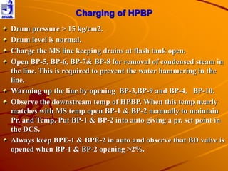
The Bypass System comprises
Two HP Bypass valve to take Main Steam
from before HPESV to Reheater inlet
bypassing the HP Turbine and
Two LP Bypass Valves that direct Steam from
Reheater outlet to Condenser bypassing the
IP & LP Turbines.
The HPLP Bypass system designed to pass
60% of the rated Turbine Steam flow [which
is 741 Te/hr].
Why Bypass System is required?
The system is intended for use at the following
times:
– For cold starts, if necessary for Boiler
temperature control.
– On hot starts, to facilitate matching of Boiler
Steam temperature and Turbine Metal
Temperature, prior to Steam admission to the
Turbines, thus achieving a faster start and
reduced thermal stress in the Turbine.
– To accommodate transient excesses in Boiler
Steam flow, thus stabilizing Boiler Steam flow
and helping to avoid operation of Boiler safety
valves.
– On load rejection or Turbine trip, the Bypass
system will handle sufficient Steam flow to
avoid a Boiler Trip, thus allowing rapid
reloading when the fault condition clears.
Operational and economic benefits for
HPLP Bypass system
 More flexible operation of Boiler & Turbine, thereby decreasing
and saving oil consumption works power due to faster cold,
warm and hot start-ups.
 Matching of Main Steam and HP Turbine metal temperatures as
well as Hot Reheat and IP Turbine metal temperatures, thus
reducing rotor and cylinder thermal stresses.
 Efficient cooling of all Boiler heating surfaces including
Reheaters.
 Less operation of Boiler and Reheater Safety valves thereby
reducing loss of costly DM Water and reduction in Noise
pollution.
 House Load operation of the Unit during Grid disturbances,
thereby remaining available for taking up external load
whenever conditions permit.
Checking required before HPBP charging.
Ensure that all permits are returned.
Physical checking of the oil tanks level.
Ensure the power supply of OSU P/p-1 & OSU
P/P-2 are healthy.
Hydraulic oil supply line up is ok.
Manual isolating v/v of BD valve is kept
open.
At least one BFP is running.
Cut in & cut out of the OSU p/p.( observe
that p/p cuts in at pr. below 100 kg/cm2 and
cuts out at pr.110 kg/cm2).
LINE UP OF HPBP
Charging of HPBP
Drum pressure > 15 kg/cm2.
Drum level is normal.
Charge the MS line keeping drains at flash tank open.
Open BP-5, BP-6, BP-7& BP-8 for removal of condensed steam in
the line. This is required to prevent the water hammering in the
line.
Warming up the line by opening BP-3,BP-9 and BP-4, BP-10.
Observe the downstream temp of HPBP. When this temp nearly
matches with MS temp open BP-1 & BP-2 manually to maintain
Pr. and Temp. Put BP-1 & BP-2 into auto giving a pr. set point in
the DCS.
Always keep BPE-1 & BPE-2 in auto and observe that BD valve is
opened when BP-1 & BP-2 opening >2%.
HP BYPASS INTERLOCKS &
PROTECTIONS
HPBP Pr CV BP-1 & BP-2 will priority close if
a) Condenser vacuum is > 0.6 kg/cm2.
b) Downstream temp. of CV is>380°C
HPBP Pr. CV BP-1 & BP-2
OUT BLOCK INC
1.) MFT & MS Press < 108 kg/cm2
Or
2.) Auto mode and (Valve Cmd > Pre defined
Cmd as per Load)
HPBP Pr. CV BP-1 & BP-2
OUT BLOCK DEC
1.) No MFT and (MS Pr <35 kg/cm2 or Load<50
MW or HRH Pr<5 kg/cm2)
And
2.) MS Press SP in Auto
And
3.) Valve position < HPBP min open i.e 10%
&
Ton: 20sec
MFT
MS Pr <35
kg/cm2 or
Load<50 MW or
HRH Pr<5
kg/cm2
&
MS Press SP in Auto
Valve position < HPBP min open
i.e. 10%
OUT BLOCK
DEC
FAST OPENING CONDITION OF
HPBP
BP-1 & BP-2 will fast open if
1.) No Priority Close and
2.) a.) Turbine trips or
b.) Generator breaker open or
c.) Turbine load shedding relay
operated or
d.)Fast open push button operated or
e.)RH Protection.
3.) Pressure deviation>5 and Pressure
>175 kg/cm2
&
NO PRIORITY CLOSE
CONDITION
TPULSE
GEN BKR OPEN OR
LSR ON(D12) OR
TURBINE TRIP(D10) OR
TURBINE TRIP (ATT) OR
RH PROTECTION(D13) OR
MANUAL FO PB OR
OTHER FO CRITERIA(D6)
3 SEC
IN 2
IN 1
IN 2 & MFT Ton(2 sec)
&
(MS Pr. – MS Pr. SP)<5
&
MS Pr. < 173 kg/cm2
Ton
1 s
Toff
2 s
&
IN 2
MFT
IN 3
FAST OPEN
AUTO MODE CONDITION OF HPBP
VALVES
BP-1 & BP-2 will automatically come in Auto
mode when FAST OPEN logic is initiated with
10 sec pulse.
MANUAL MODE CONDITION OF
HPBP VALVES
BP-1 & BP-2 will automatically come in Manual
mode when:
1.) Priority Close
2.) Valve PFT Tx fail.
3.) O.S.U 1 and O.S.U 2 Oil pressure V. low
OPERATING CONDITIONS OF SPRAY CV.
Spray CV BPE-1 & BPE-2 will close if
BP-1/BP-2 opening is< 2%.
BPE-1/BPE-2 will open in the case of
fast opening.
BPE-1/BPE-2 switch over to auto if BP-
1/BP-2 opening>2%.
BPE-1/BPE-2 get auto block if oil
pressure is very low.

Hplpbp

  • 1.
    HP BYPASS SYSTEM ControlPhilosophy and Protection
  • 2.
    General The Bypass Systemcomprises Two HP Bypass valve to take Main Steam from before HPESV to Reheater inlet bypassing the HP Turbine and Two LP Bypass Valves that direct Steam from Reheater outlet to Condenser bypassing the IP & LP Turbines. The HPLP Bypass system designed to pass 60% of the rated Turbine Steam flow [which is 741 Te/hr].
  • 3.
    Why Bypass Systemis required? The system is intended for use at the following times: – For cold starts, if necessary for Boiler temperature control. – On hot starts, to facilitate matching of Boiler Steam temperature and Turbine Metal Temperature, prior to Steam admission to the Turbines, thus achieving a faster start and reduced thermal stress in the Turbine. – To accommodate transient excesses in Boiler Steam flow, thus stabilizing Boiler Steam flow and helping to avoid operation of Boiler safety valves. – On load rejection or Turbine trip, the Bypass system will handle sufficient Steam flow to avoid a Boiler Trip, thus allowing rapid reloading when the fault condition clears.
  • 5.
    Operational and economicbenefits for HPLP Bypass system  More flexible operation of Boiler & Turbine, thereby decreasing and saving oil consumption works power due to faster cold, warm and hot start-ups.  Matching of Main Steam and HP Turbine metal temperatures as well as Hot Reheat and IP Turbine metal temperatures, thus reducing rotor and cylinder thermal stresses.  Efficient cooling of all Boiler heating surfaces including Reheaters.  Less operation of Boiler and Reheater Safety valves thereby reducing loss of costly DM Water and reduction in Noise pollution.  House Load operation of the Unit during Grid disturbances, thereby remaining available for taking up external load whenever conditions permit.
  • 6.
    Checking required beforeHPBP charging. Ensure that all permits are returned. Physical checking of the oil tanks level. Ensure the power supply of OSU P/p-1 & OSU P/P-2 are healthy. Hydraulic oil supply line up is ok. Manual isolating v/v of BD valve is kept open. At least one BFP is running. Cut in & cut out of the OSU p/p.( observe that p/p cuts in at pr. below 100 kg/cm2 and cuts out at pr.110 kg/cm2).
  • 7.
  • 8.
    Charging of HPBP Drumpressure > 15 kg/cm2. Drum level is normal. Charge the MS line keeping drains at flash tank open. Open BP-5, BP-6, BP-7& BP-8 for removal of condensed steam in the line. This is required to prevent the water hammering in the line. Warming up the line by opening BP-3,BP-9 and BP-4, BP-10. Observe the downstream temp of HPBP. When this temp nearly matches with MS temp open BP-1 & BP-2 manually to maintain Pr. and Temp. Put BP-1 & BP-2 into auto giving a pr. set point in the DCS. Always keep BPE-1 & BPE-2 in auto and observe that BD valve is opened when BP-1 & BP-2 opening >2%.
  • 10.
    HP BYPASS INTERLOCKS& PROTECTIONS HPBP Pr CV BP-1 & BP-2 will priority close if a) Condenser vacuum is > 0.6 kg/cm2. b) Downstream temp. of CV is>380°C
  • 12.
    HPBP Pr. CVBP-1 & BP-2 OUT BLOCK INC 1.) MFT & MS Press < 108 kg/cm2 Or 2.) Auto mode and (Valve Cmd > Pre defined Cmd as per Load)
  • 15.
    HPBP Pr. CVBP-1 & BP-2 OUT BLOCK DEC 1.) No MFT and (MS Pr <35 kg/cm2 or Load<50 MW or HRH Pr<5 kg/cm2) And 2.) MS Press SP in Auto And 3.) Valve position < HPBP min open i.e 10%
  • 16.
    & Ton: 20sec MFT MS Pr<35 kg/cm2 or Load<50 MW or HRH Pr<5 kg/cm2 & MS Press SP in Auto Valve position < HPBP min open i.e. 10% OUT BLOCK DEC
  • 17.
    FAST OPENING CONDITIONOF HPBP BP-1 & BP-2 will fast open if 1.) No Priority Close and 2.) a.) Turbine trips or b.) Generator breaker open or c.) Turbine load shedding relay operated or d.)Fast open push button operated or e.)RH Protection. 3.) Pressure deviation>5 and Pressure >175 kg/cm2
  • 18.
    & NO PRIORITY CLOSE CONDITION TPULSE GENBKR OPEN OR LSR ON(D12) OR TURBINE TRIP(D10) OR TURBINE TRIP (ATT) OR RH PROTECTION(D13) OR MANUAL FO PB OR OTHER FO CRITERIA(D6) 3 SEC IN 2 IN 1 IN 2 & MFT Ton(2 sec) & (MS Pr. – MS Pr. SP)<5 & MS Pr. < 173 kg/cm2 Ton 1 s Toff 2 s & IN 2 MFT IN 3 FAST OPEN
  • 21.
    AUTO MODE CONDITIONOF HPBP VALVES BP-1 & BP-2 will automatically come in Auto mode when FAST OPEN logic is initiated with 10 sec pulse.
  • 23.
    MANUAL MODE CONDITIONOF HPBP VALVES BP-1 & BP-2 will automatically come in Manual mode when: 1.) Priority Close 2.) Valve PFT Tx fail. 3.) O.S.U 1 and O.S.U 2 Oil pressure V. low
  • 24.
    OPERATING CONDITIONS OFSPRAY CV. Spray CV BPE-1 & BPE-2 will close if BP-1/BP-2 opening is< 2%. BPE-1/BPE-2 will open in the case of fast opening. BPE-1/BPE-2 switch over to auto if BP- 1/BP-2 opening>2%. BPE-1/BPE-2 get auto block if oil pressure is very low.