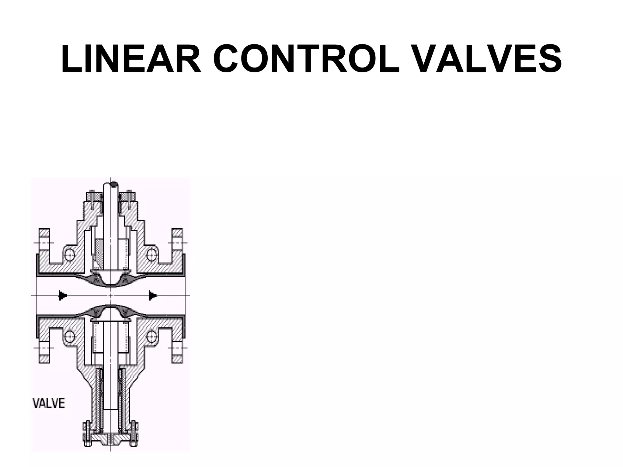
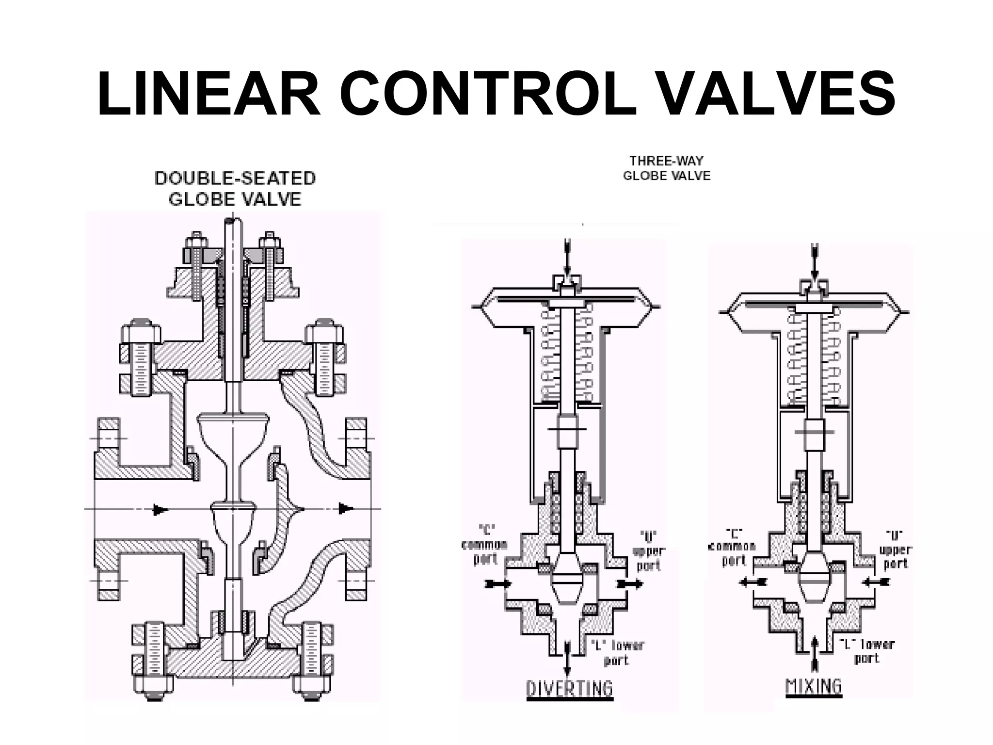
Control valves are used to control process variables like pressure, flow, level and temperature. They work with a controller to form a control loop. The control valve manipulates the flow of process fluids like gas, steam, water or chemicals. It has a valve body, internal trim parts, an actuator and accessories. Control valves are classified based on their design as linear or rotary, and based on operation as throttling or on-off. Cavitation or flashing can occur if the downstream pressure reduces below the vapor pressure of the fluid.
2. • Introduction to Control Valves
• Control Valves photographs
• Control Valves- classification
• Detailed operation
• installation Guidelines
• Control Valve specifications in details
• Applications
• Terminology
Index
3.
4.
5. Why and What Is
A Control Valve?
• Process plants consist of hundreds, or networked
together to produce a product to be offered for sale.
• Each of these control loops is designed to keep
some important process variable such as pressure,
flow, level, temperature,etc. within a required
operating range to ensure the quality of the end
• product.
• Each of these loops receives and internally creates
disturbances that detrimentally affect the process
• variable, and interaction from other loops in the
network provides disturbances that influence the
process variable.
6. • To reduce the effect of these load disturbances,
sensors and transmitters collect information about the
process variable and its relationship to some desired
set point.
• A controller then processes this information and
decides should be after a load disturbance occurs.
• When all the measuring, comparing, and calculating
are done, some type of final control element must
implement the strategy selected by the controller.
• The most common final control element in the
process control industries is the control valve.
7. • The control valve manipulates a flowing fluid,
such as gas, steam, water, or chemical
compounds,
• To compensate for the load disturbance
• and keep the regulated process variable as close
as possible to the desired set point.
• The control valve assembly typically consists
of--
• valve body
• internal trim parts,
• an actuator to provide the motive power to
operate the valve,
• and a variety of additional valve accessories, which
can include positioners, transducers, supply
pressure regulators, manual operators, or limit
switches.
8. CONTROL VALVE
• A Control Valve performs a special task, controlling
the flow of fluids so a process variable such as fluid
pressure, fluid level or temperature can be
controlled.
• In addition to controlling the flow, a control valve
may be used to shut off flow.
• A control valve may be defined as a valve with a
powered actuator that responds to an external
signal.
• The signal usually comes from a controller. The
controller and valve together form a basic control
loop.
• The control valve is seldom full open or closed but in
an intermediate position controlling the flow of fluid
9. VALVE FLOW
TERMINOLOGY
• CV: The Flow Coefficient, CV, is a
dimensionless value that relates to a valve’s
flow capacity.
• Its most basic form is
• where Q=Flow rate and .P=pressure drop
across the valve.
• The CV value increases if the flow rate
increases or if the decreases.
10. • Vena Contracta: The vena contracta is where the
jet of flowing fluid is the smallest immediately
downstream of the trim's throttle point.
• At the vena contracta, the fluid's velocity is the
highest and the fluid's pressure is the lowest.
• Vapor Pressure: A fluid's vapor pressure is the
pressure where the fluid will change from a liquid
to a vapor.
• The liquid will change to a vapor below the vapor
pressure and a vapor will change to a liquid above
the vapor pressure.
• The vapor pressure increases as the temperature
increases.
11. • Rangeability: Rangeability is the ratio
of maximum to minimum controllable .
• This is also sometimes called Ratio
or Turndown.
21. Control Valves Selection
Procedure
• Estimate the size of the valve by taking one
size smaller than the line. If there is no line
size available calculate using a velocity of
5m/s for liquids and 40m/s for gases or
vapours.
• • Use the chart to determine the valve type
which best satisfies the requirements of the
• application.
22. • Generally for larger sizes of l00mm or
greater the order of preference assuming cost
to be of a high priority would be as follows:
• • Butterfly
• • Disk
• • Rotary plug
• • Ball
• but using globe if the pressure drop is high
and using pinch/diaphragm valves for slurries.
23. • For small valves of less than l00mm the
order of preference would be:
• • Globe
• • Rotary plug
• • Ball
• • Pinch/Diaphragm
• Conclusion
• There is nothing definitive about selecting a
type of valve.
24.
25.
26.
27.
28. Line- Explanation of Terms
and Definitions -Examples
• PROJECT Specify project name for which control
valve is intended. XYZ Nuclear PS
• UNIT Specify unit within project. #1
• P.O. Specify purchase order number from purchaser
to control valve manufacturer.P.O. 12345
• ITEM Specify item number of purchase order. 3
• CONTRACT Specific contract number of project for
purchaser's reference. 56-V-32510
• MFR SERIAL This line may show the valve
manufacturer's serial number(s) and is normally filled
in at the time of shipment of the valve.
29. • Serial numbers often contain the manufacturer's
shop order number. C12650-3
• DATA SHEET Specify data sheet number.
Normally assigned by purchaser. 3 of 12
• SPEC Specify number of technical specification on
which valve selection is based. FL-13265-A
• TAG Specify tag number, if any, used to designate
location of valve. FV-103
• DWG Specify piping and instrumentation diagram
number, loop diagram number, engineering flow
diagram number, etc. 17-453
• SERVICE Describe service of control valve and/or
pipe line number. Feed water control
30. • 1 Describe fluid flowing into valve and its state.
Indicate corrosive or erosive service and the
corrosive or erosive agents.
• Superheated steam, Saturated water, Crude oil and
natural gas.
• 2 Specify volumetric or mass flow rate at inlet or
standard conditions.
• 3 Specify inlet pressure (gauge or absolute).
• 5000 psig 2000 kPa abs.
• 4 Specify outlet pressure (gauge or absolute).
• 1000 psig 400 kPa gauge
31. • 5 Specify inlet temperature in °F, °R, °C or K. Must
agree with state of fluid and its inlet
pressure.750°F / 200°C
• 6 Specify specific weight (in lb/ft3 or kg/m3),
specific gravity, or molecular weight of fluid.
Identify the appropriate term. 61.9 lb/ ft3
• 7 Specify viscosity in appropriate units for liquids or
specific heats ratio for gases.
• 20 centi poise 17.8 centistokes
• 8 Specify vapor (saturation) pressure at inlet
temperature in absolute units. Only required for
liquid flow. 680 psia 46.9 bar abs.
32. • 9 Specify required V as calculated for each condition
per ANSI/ ISA S75.01-1985. No additional safety
(oversize) factor should be included at this point.260
• 13 & 14 Specify size and schedule (or wall thickness
if nonstandard) of pipe line into which valve is
installed. 8" SCH 40, 15" OD x 0. 500" wall, DN 200
• 16 Specify type of valve body. Globe (through,
angle) Split body, Double port, Butterfly, Ball, Pinch
• 17 Specify nominal size of valve body. Specify ANSI
class in accordance with ANSI B16.34-81. 4"
• 600 2500 SPECIAL
• 18 Specify maximum pressure and temperature of
the valve. 2500 psig, 650°F
• 19 Specify manufacturer and model number. XYZ
Controls Model 719-2
33. • 20 Specify body and bonnet material. Steel, ASTM
A216, WCB
• 21 Specify body liner material, if any, and its inside
diameter. Polyurethane, 3.9"
• 22 & 23 Specify end connection. May be integral or
welded onto body.
• 27 Specify type of bonnet. Standard, Cooling fin,
Extended
• 29 Specify packing material. Graphite impreg.
asbestos, TFE, Non-asbestos
• 30 Specify type of packing. Braided, Molded V-ring,
Laminated filament, Pressure/Vacuum
• 32 Specify type of trim. Single seat cage-guided,
Multi-stage, Multihole,Top- and bottom-guided,
Double seat
34. • 33 Specify nominal size and rated travel of
installed trim. 2", 50 mm
• 34 Specify inherent flow characteristic of installed
trim. Linear, Equal %, Modified parabolic, Quick-
opening
• 35 Specify whether trim is balanced or unbalanced.
• 37 Specify closure member, i.e., plug, ball, or disk
material as applicable.17-4 PH H-1150, 316
• 38 Specify seat material. 420 hardened 316 hard
faced
• 39 Specify cage, bearing, or guide material. 410
hardened
• 40 Specify stem material. 17-4 PH H-1150, 316
35. • 43 Specify hazardous location classification per the
National Electrical Code®, ANSI/NFPA 70-1987.
• NEC® Class I, Div. 1, Group C
• 44-52 Specify special requirements and/or
accessories not covered elsewhere.
• Solenoid valves, E/P transducer.
• 53 Specify type of actuator. Diaphragm, pneumatic,
Hydr. piston, double-acting, Pneumatic rotary vane
• 54 Specify manufacturer and model number. XYZ
Controls, P-100-160
• 55 Specify nominal size and effective diaphragm/
piston area. 8", 160 square inch, 0.2 m2
• 56 Specify whether actuator is for on/off or
modulating service. Modulating On/ off
36. • 57 Specify whether spring, if any, acts to open or to
close valve. Open Close None
• 58 Specify maximum pressure for which the
actuator is designed. 100 psig 60 kPa
• 59 Specify minimum pressure required to fully
stroke the installed valve under specified
conditions. 65 psig
• 60 & 61 Specify limits of available air or hydraulic
supply pressure. If upper limit is greater than line
58, a reducing valve (air set) should be furnished.
• 90 psig/ 70 psig
• 62 Specify the pressures in the actuator when valve
starts travel and at its rated travel position without
fluid forces acting on the valve. 8/32 psig10/22 psig
• 1.2/2.1 Kpa
37. • 63 Specify orientation of actuator as "VERT.UP" or
"VERT.DOWN“ (vertical) or "HORIZ." (horizontal).
For rotary valves, also specify whether mounting is
"RH" (right-hand) or "LH" (left- hand) as viewed
from valve inlet, if appropriate. Specify additional
information as appropriate or provide sketch.
• 64 Specify type and orientation of hand wheel
(manual override), if any. Top-mounted Side-
mounted.
• 67 Specify input signal range for full travel. 3-15
psig, 200-100 kPa, 4-20 mA
• 68 Specify type of positioner. None Single acting
• Double acting
• 84 Specify leakage class per ANSI/FCI 70-2-76.
Class IV
41. Cavitation
• Cavitation is a two stage
phenomena with liquid flow.
• The first stage is the formation of
vapor bubbles in the liquid as the
fluid passes through the trim and the
pressure is reduced below the fluid's
vapor pressure.
• The second stage is the collapse of
the vapor bubbles as the fluid
passes the vena contracta and the
pressure recovers and increases
above the vapor pressure.
• The collapsing bubbles are very
destructive when they contact metal
parts and the bubble collapse may
42. Flashing
• Flashing is similar to cavitation except the
vapor bubbles do not collapse, as the
downstream pressure remains less than the
vapor pressure.
• The flow will remain a mixture of vapor and
liquid.