Downloaded 131 times
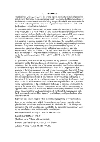

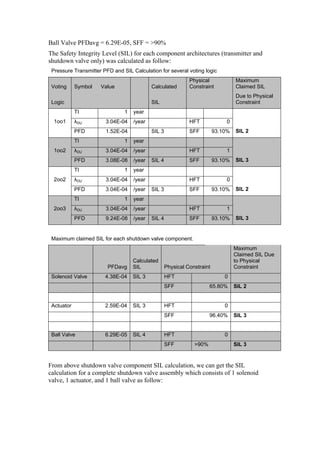
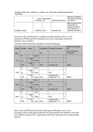
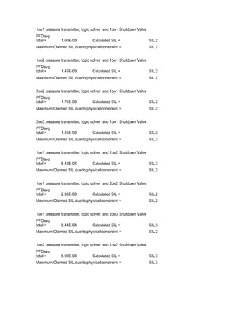
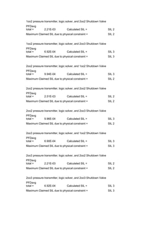
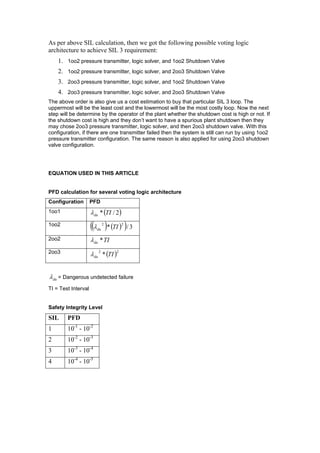
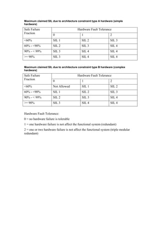
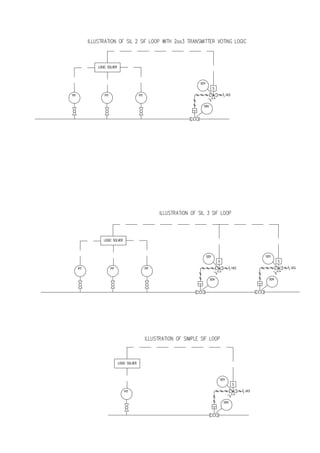

The document discusses different voting logic architectures (1oo1, 1oo2, 2oo2, 2oo3) used in safety instrumented systems and how to determine the appropriate architecture based on Safety Integrity Level (SIL) requirements. It provides an example of selecting a voting logic architecture to meet a SIL 3 requirement for a high pressure pipeline. Based on calculations of Probability of Failure on Demand for different combinations, architectures with 1oo2 pressure transmitters and either 1oo2 or 2oo3 shutdown valves can meet the SIL 3 requirement.


