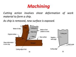
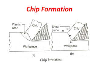
1) Chip formation involves the shear deformation of work material to form a chip as new material is exposed during cutting.
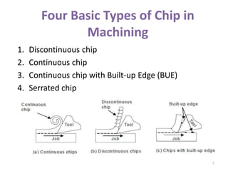
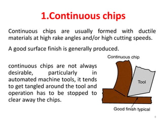
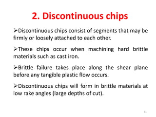
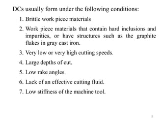
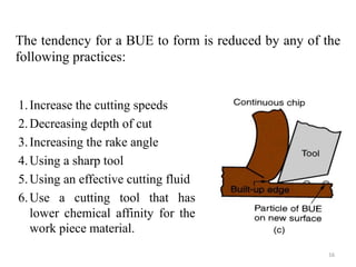
2) There are four basic types of chips in machining: continuous, discontinuous, serrated, and those with built-up edge (BUE).
3) The type of chip formed depends on factors like the work material, tool geometry, cutting speeds and feeds, and machining environment. Understanding chip formation helps optimize the machining process.