Download as PDF, PPTX
![Determination of sheet material properties CPF
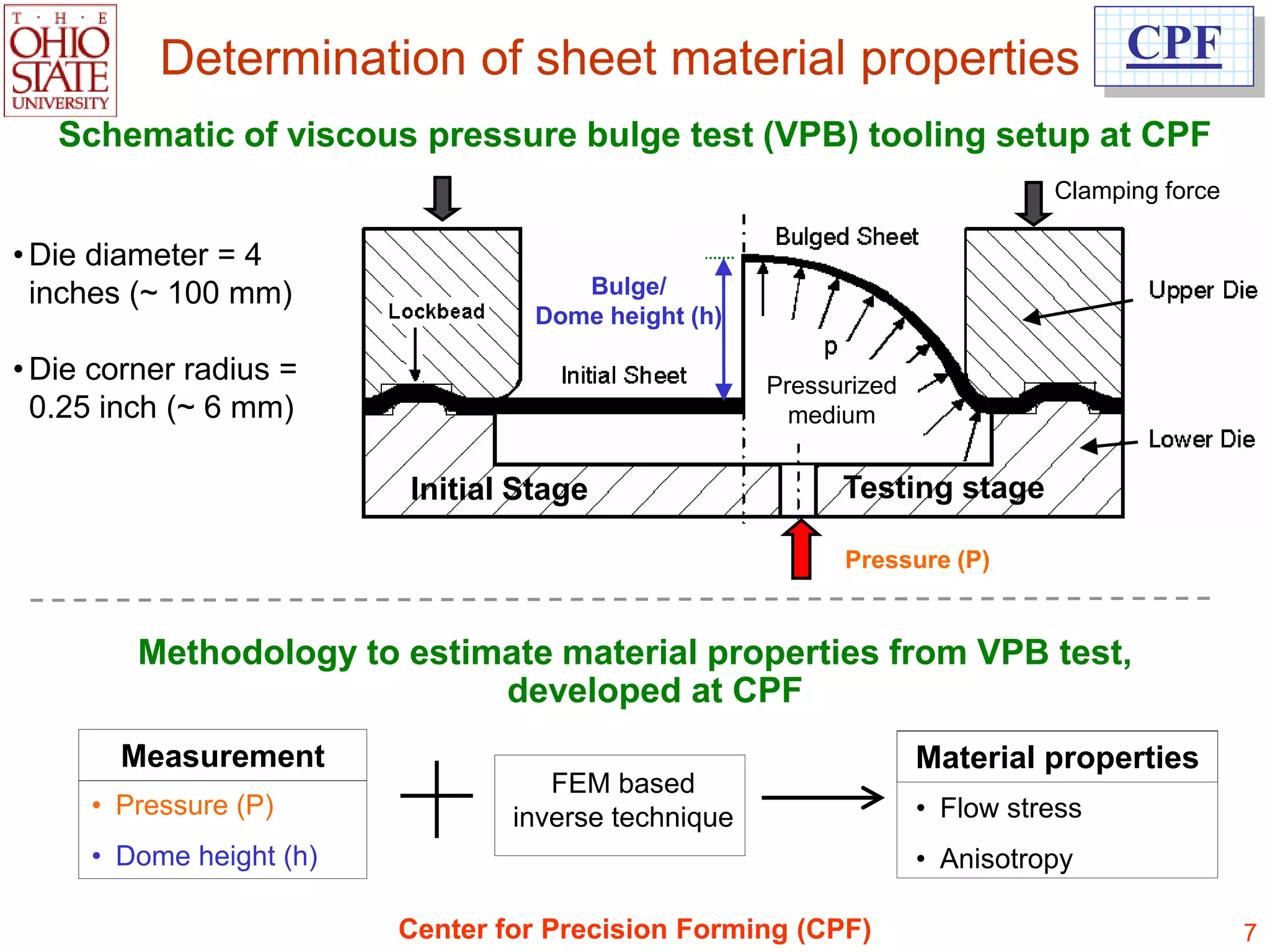
In common practice, the uniaxial tensile test is used to determine the properties/flow stress and
formability of sheet metal.
Tensile test does not emulate biaxial deformation conditions observed in stamping.
Due to early necking in tensile test, stress/strain data (flow stress) is available for small strains.
Necking begins
Engineering Stress-Strain Curve True Stress-Strain Curve = Flow stress
In AHSS, the strain hardening exponent [n-value] and Young‟s modulus [E] change
with deformation (strain).
Center for Precision Forming (CPF) 5](https://image.slidesharecdn.com/simulationforforming-121213222146-phpapp01/75/Simulation-for-forming-5-2048.jpg)
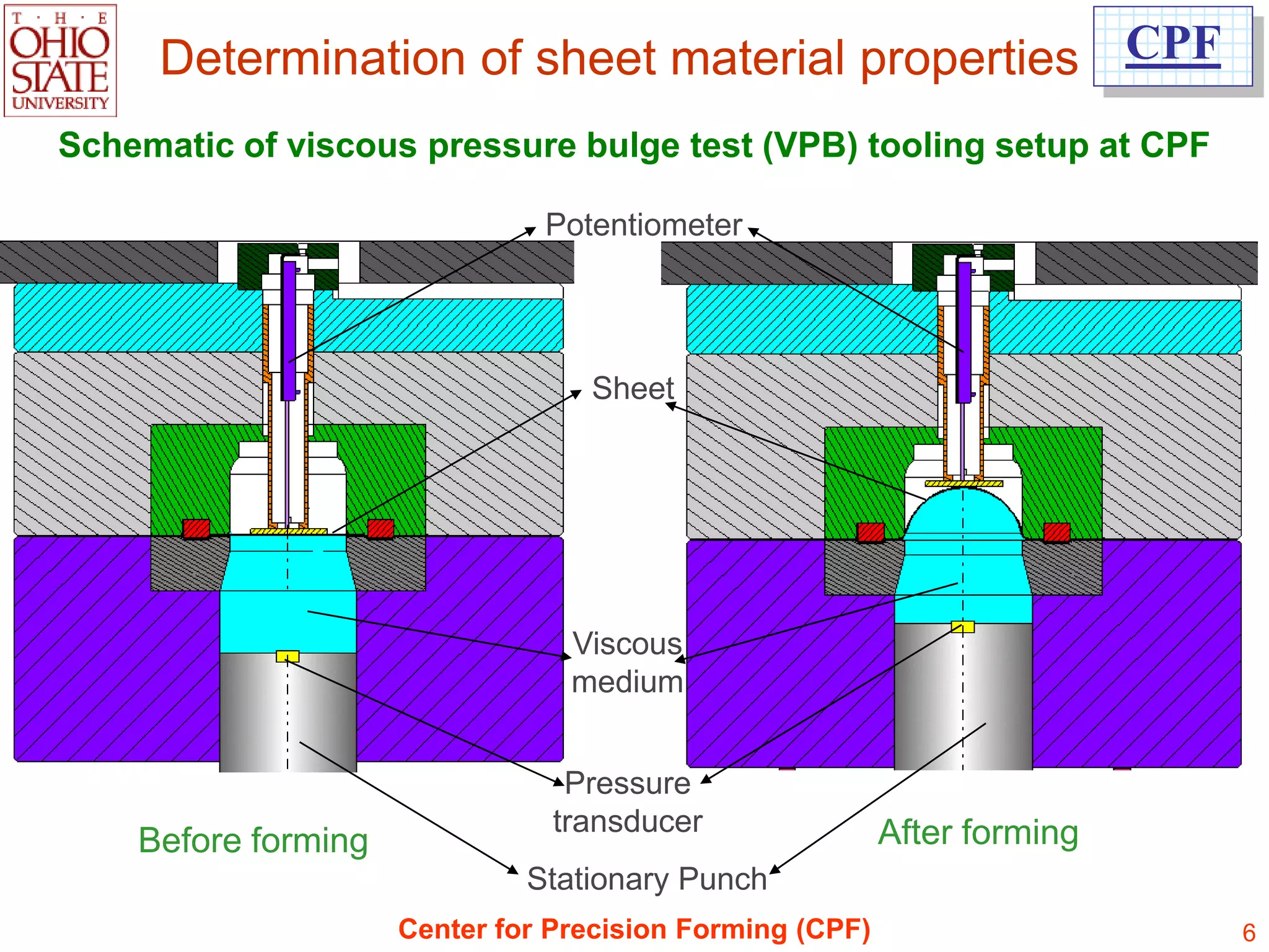
![Determination of sheet material properties CPF
Bulge test as an indicator of incoming sheet quality
Graph shows dome height comparison for SS 304 sheet material from eight
different batches/coils [5 samples per batch].
Highest formability G , Most consistent F
Lower formability and inconsistent H
Center for Precision Forming (CPF) 10](https://image.slidesharecdn.com/simulationforforming-121213222146-phpapp01/75/Simulation-for-forming-10-2048.jpg)
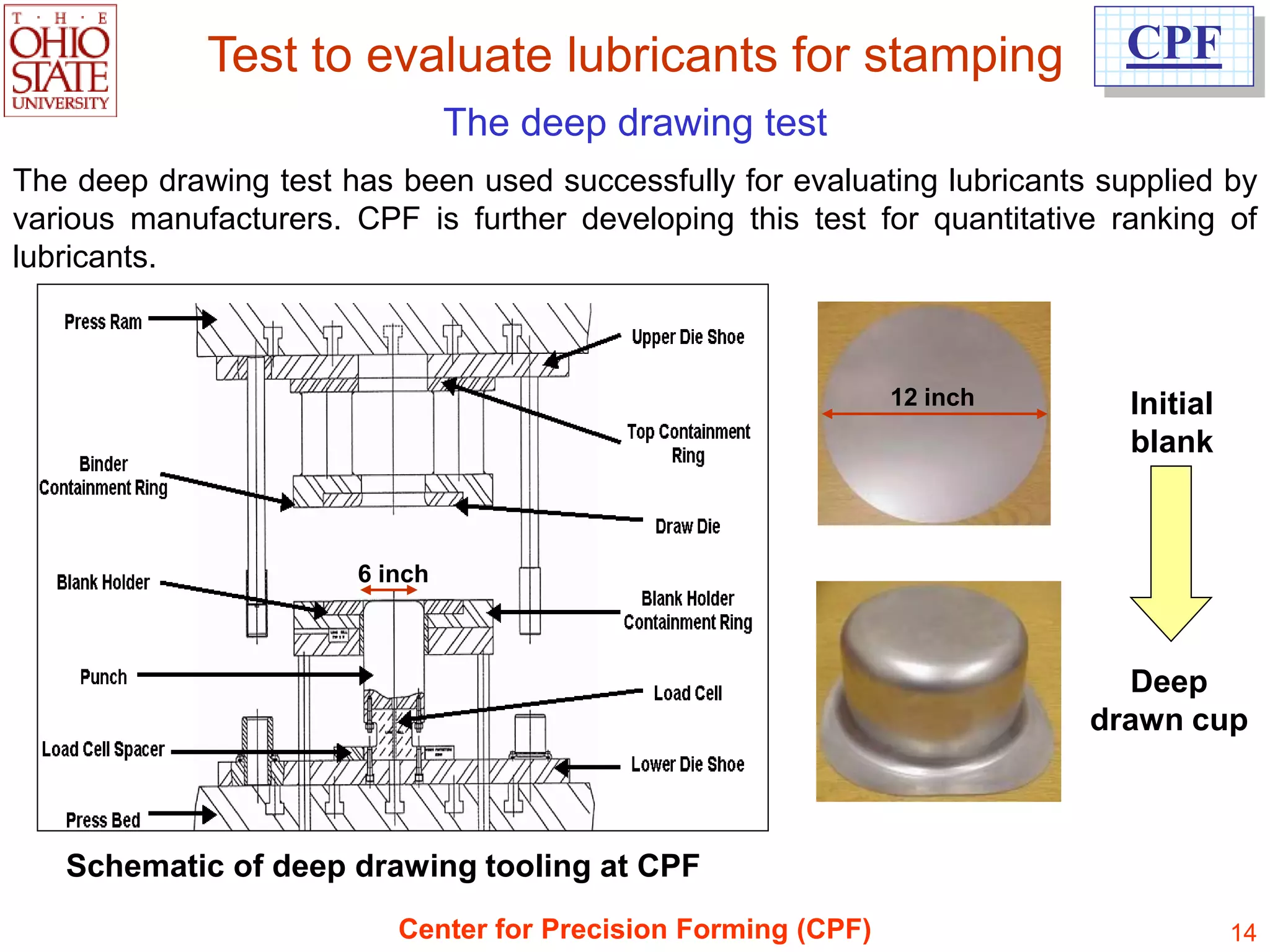
![Stamping lubricants in the CPF
automotive industry
Process with oil-based (wet) lubricant
Additional Degreasing
Pre-Oiling Oiling (optional)
Decoiling and (optional) (optional)
cutting
Stacking
Deep Drawing +
Blanks
subsequent
(dry or
blanking
pre-oiled)
operations
[Courtesy: M. Pfestorf, 2005, BMW ]
Center for Precision Forming (CPF) 12](https://image.slidesharecdn.com/simulationforforming-121213222146-phpapp01/75/Simulation-for-forming-12-2048.jpg)
![Stamping lubricants in the CPF
automotive industry
Process with dry-film lubricant
Deep Drawing +
Decoiling / Recoiling Decoiling subsequent blanking
with Lube coating by and cutting Stacking operations
immersion or spraying Blanks
Hot bath
[Courtesy: M. Pfestorf, 2005, BMW ]
Center for Precision Forming (CPF) 13](https://image.slidesharecdn.com/simulationforforming-121213222146-phpapp01/75/Simulation-for-forming-13-2048.jpg)
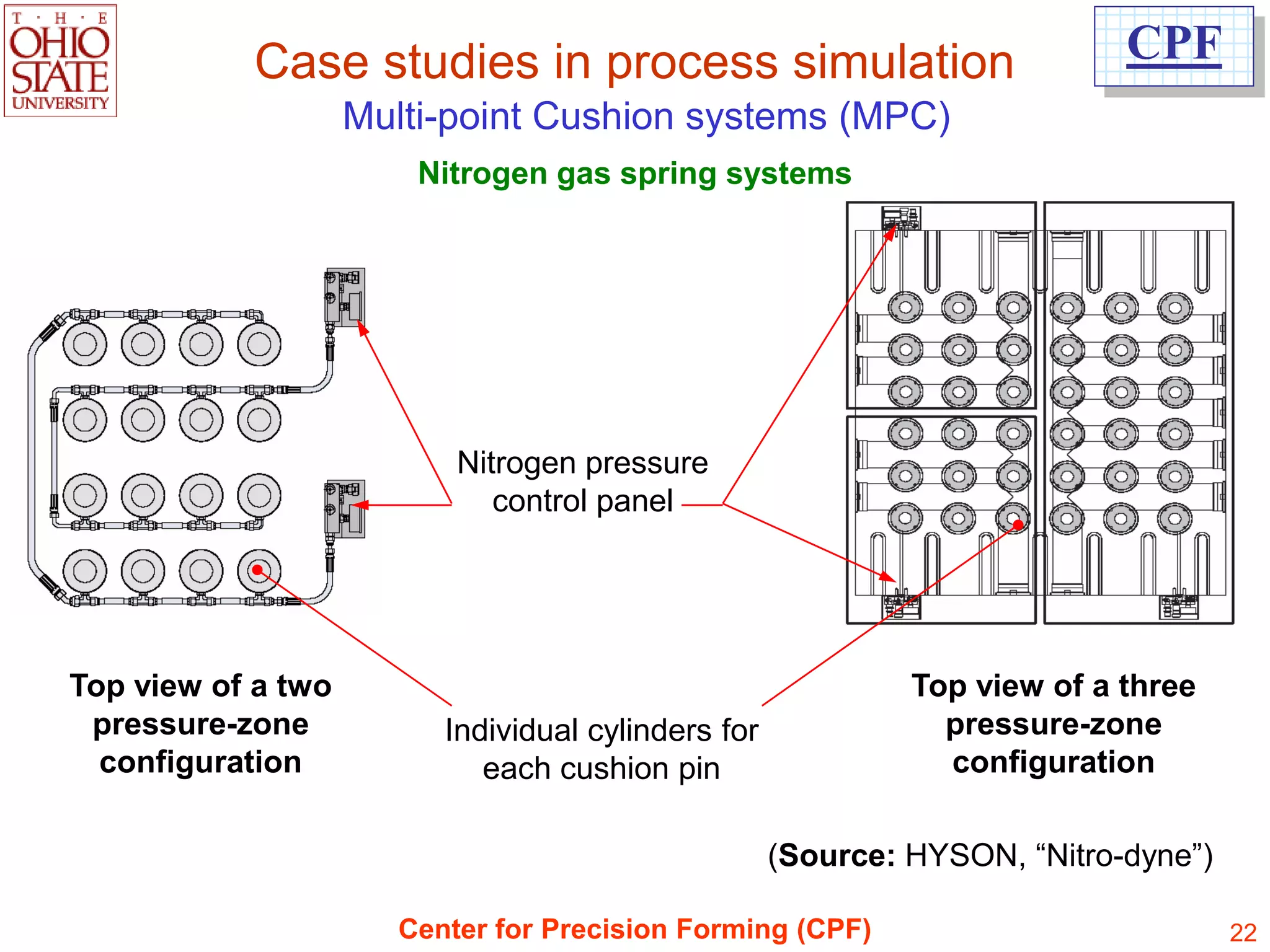
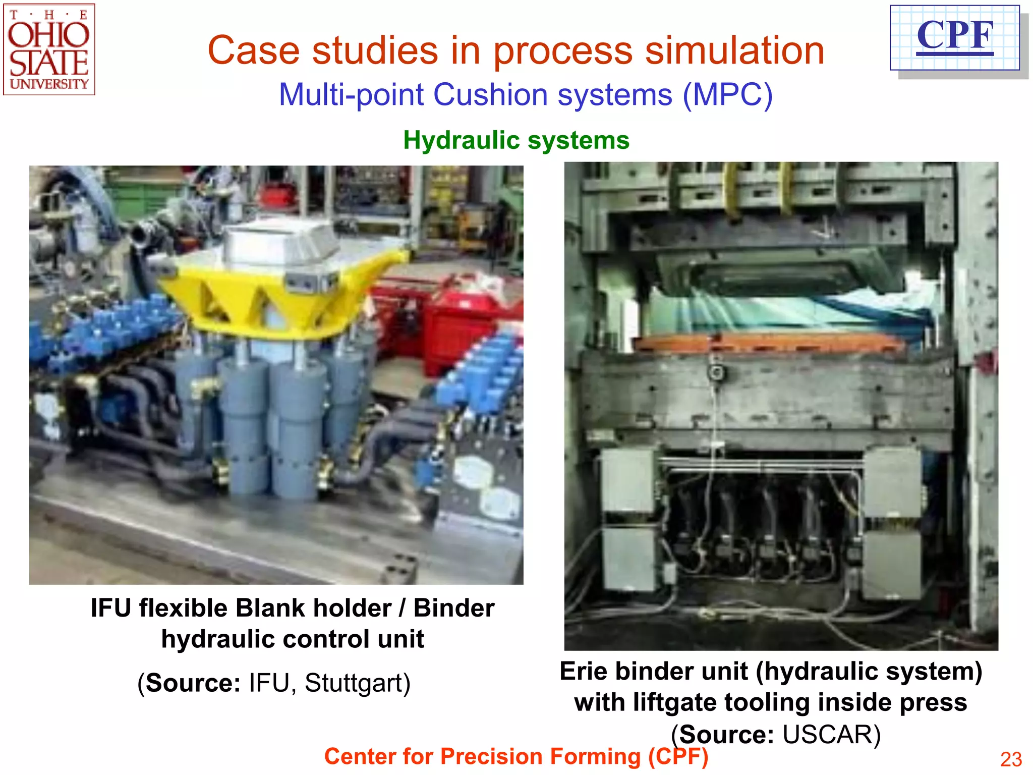
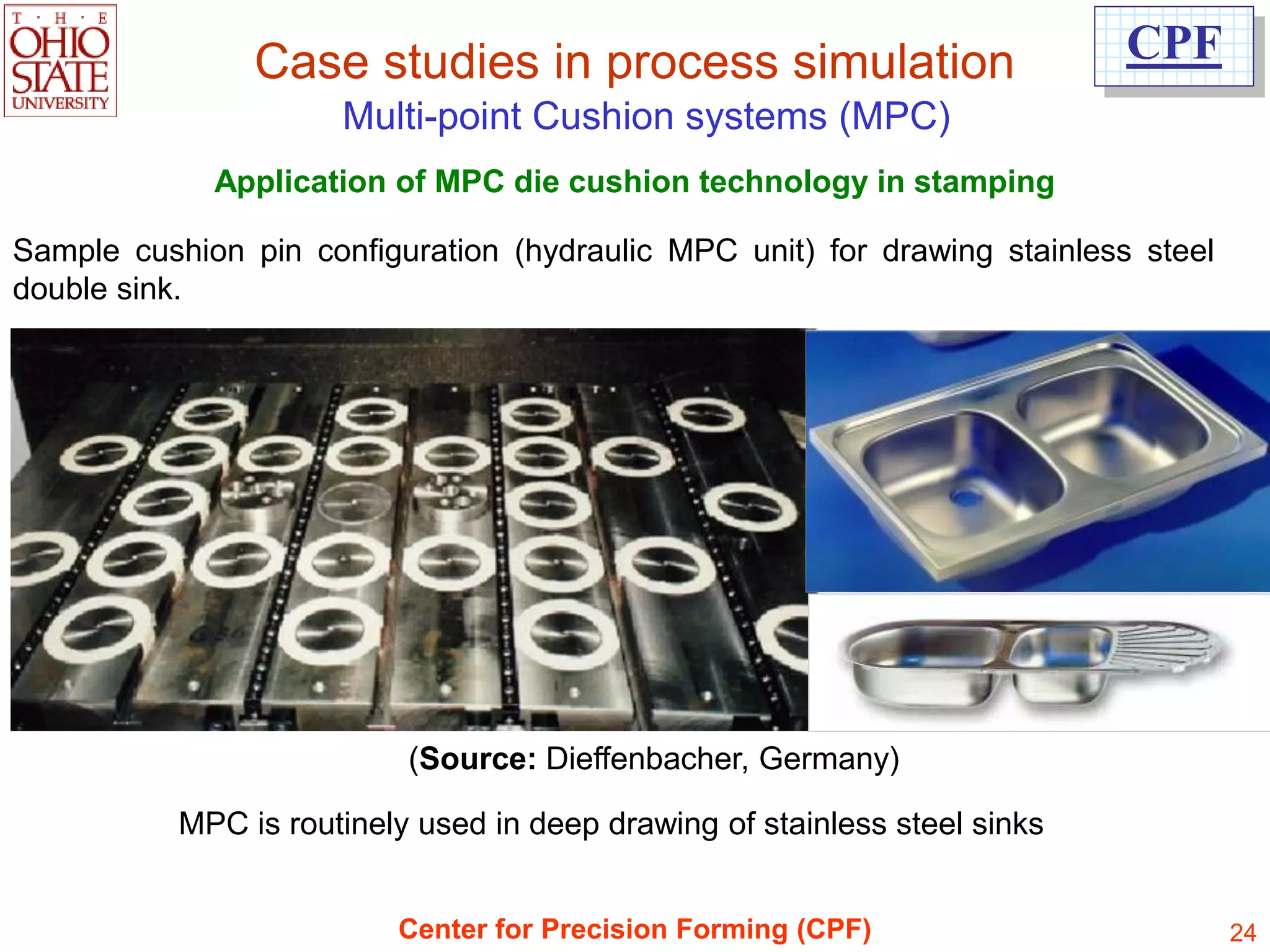
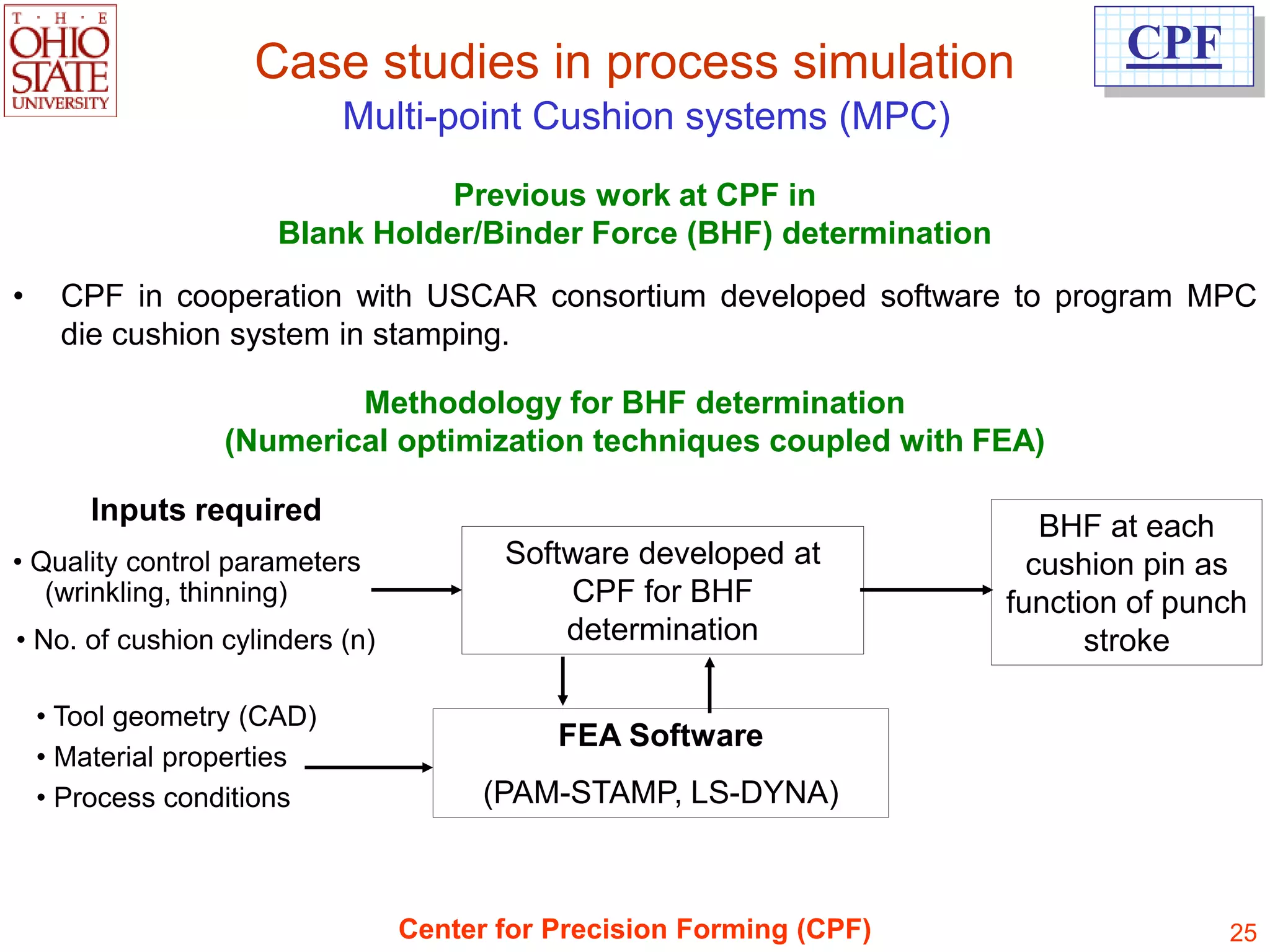
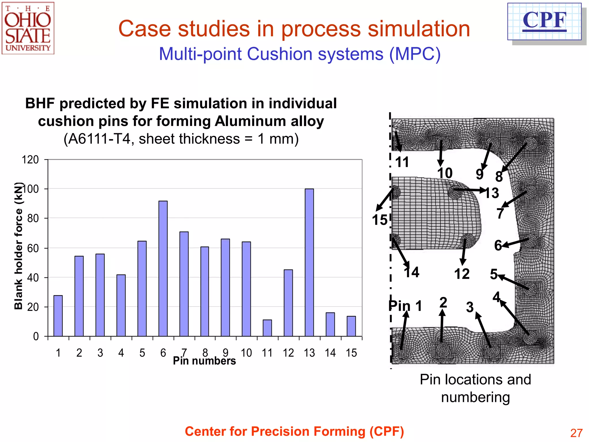
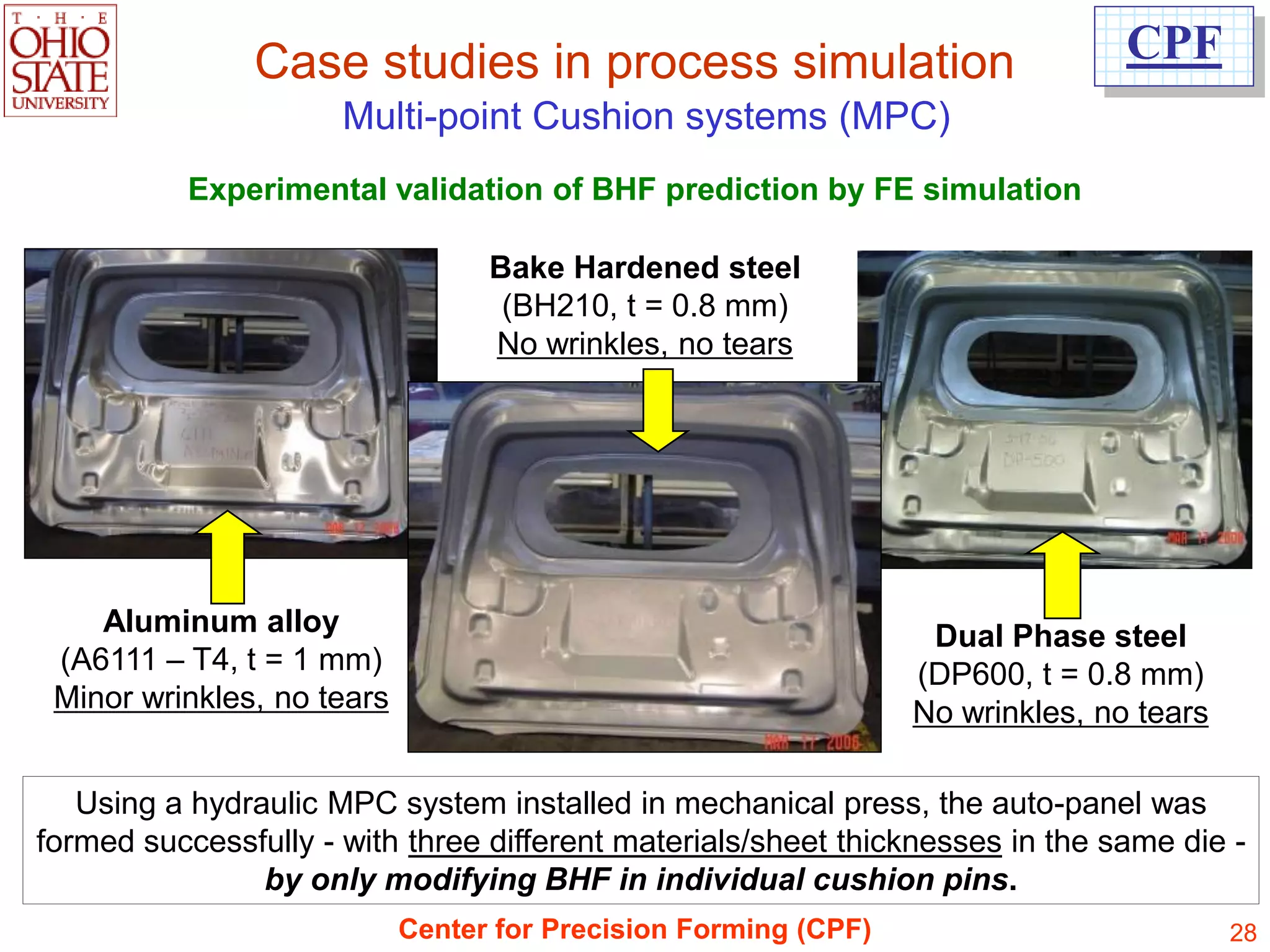
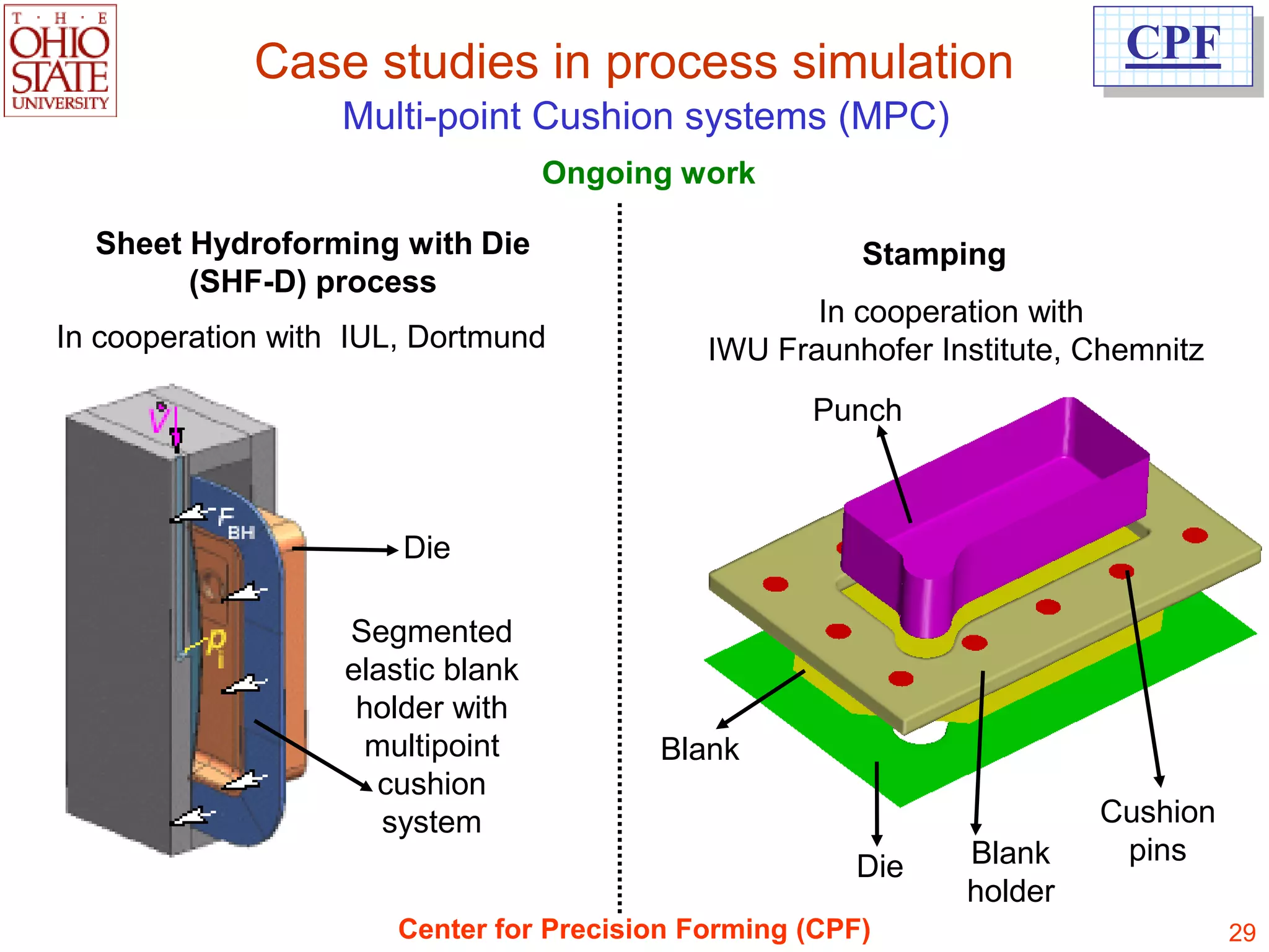
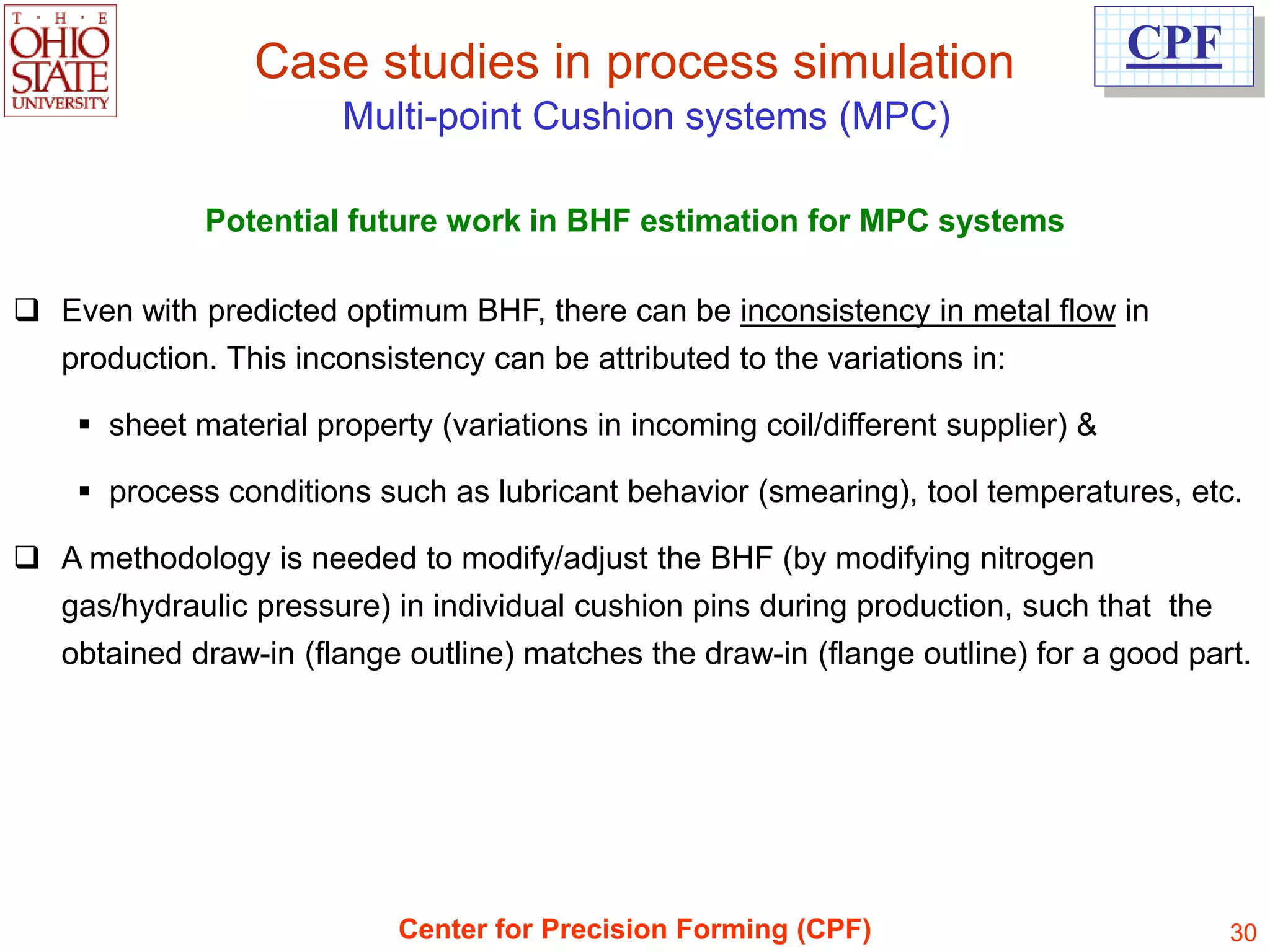
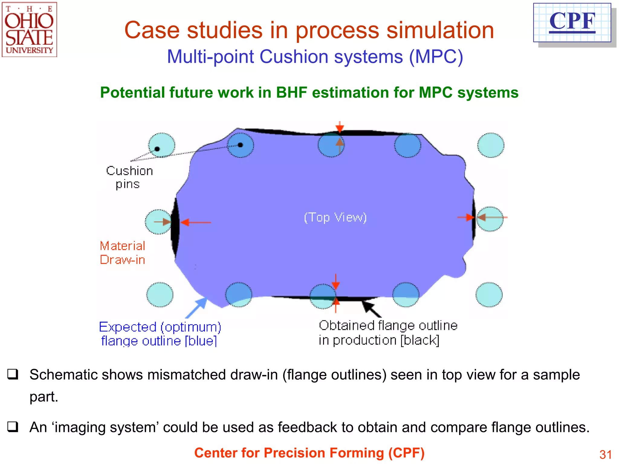
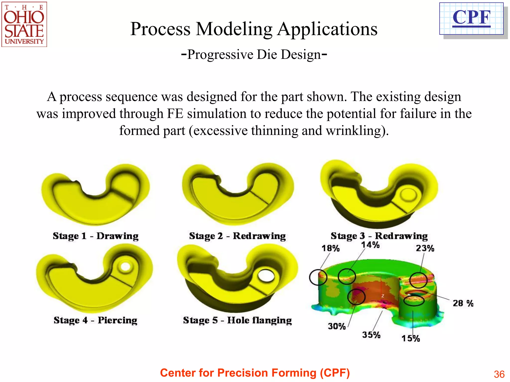
![Case studies in process simulation CPF
Multi-point Cushion systems (MPC)
FE model
Die Estimation of Blank Holder Force (BHF)
varying in each cushion pin & constant
in stroke, using FE simulation coupled
with numerical optimization, developed
at CPF.
Sheet
Geometry : Lift gate inner
Material : Aluminum alloy, AA6111-T4
Beads
Initial sheet thickness : 1 mm
Inner Segmented blank holder
Binder [Source: USCAR / CPF - OSU]
Cushion Pin Outer
Binder
Punch
Center for Precision Forming (CPF) 26](https://image.slidesharecdn.com/simulationforforming-121213222146-phpapp01/75/Simulation-for-forming-26-2048.jpg)
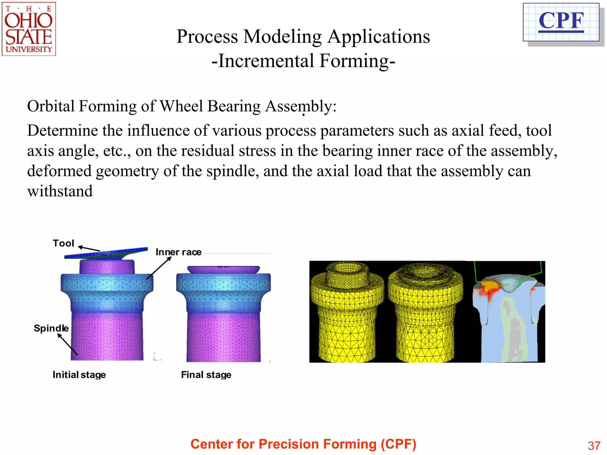
![Case studies in process simulation CPF
Warm forming of Al alloys, Mg alloys
and stainless steels
Results of elevated temperature formability study
3
Limiting Drawing Ratio (LDR)
• Material Al5754-O,
2.9
t = 1.3 mm
2.8 • Forming velocity = 5mm/sec
2.7 • Influence of temperature on the
deep drawability of round cups
2.6 (Ø 40 mm) was investigated.
2.5
• Similar studies were conducted
2.4 for higher forming velocities of
250 275 300 15 mm/sec and 50 mm/sec.
Die and Blank holder temperature (deg C)
[In cooperation with AIDA America, Dayton]
Center for Precision Forming (CPF) 35](https://image.slidesharecdn.com/simulationforforming-121213222146-phpapp01/75/Simulation-for-forming-35-2048.jpg)
![CPF
Summary
Process simulation using FEA is state of the art for die/process design.
Determination of reliable input parameters [material properties /interface friction
conditions] is a key element in successful application of process simulation.
For practical application, stamping lubricants should be evaluated in the
laboratory under near-production conditions (speed, temperature, interface
pressure). Reliable friction coefficient values needed for process simulation can
be obtained from these laboratory tests.
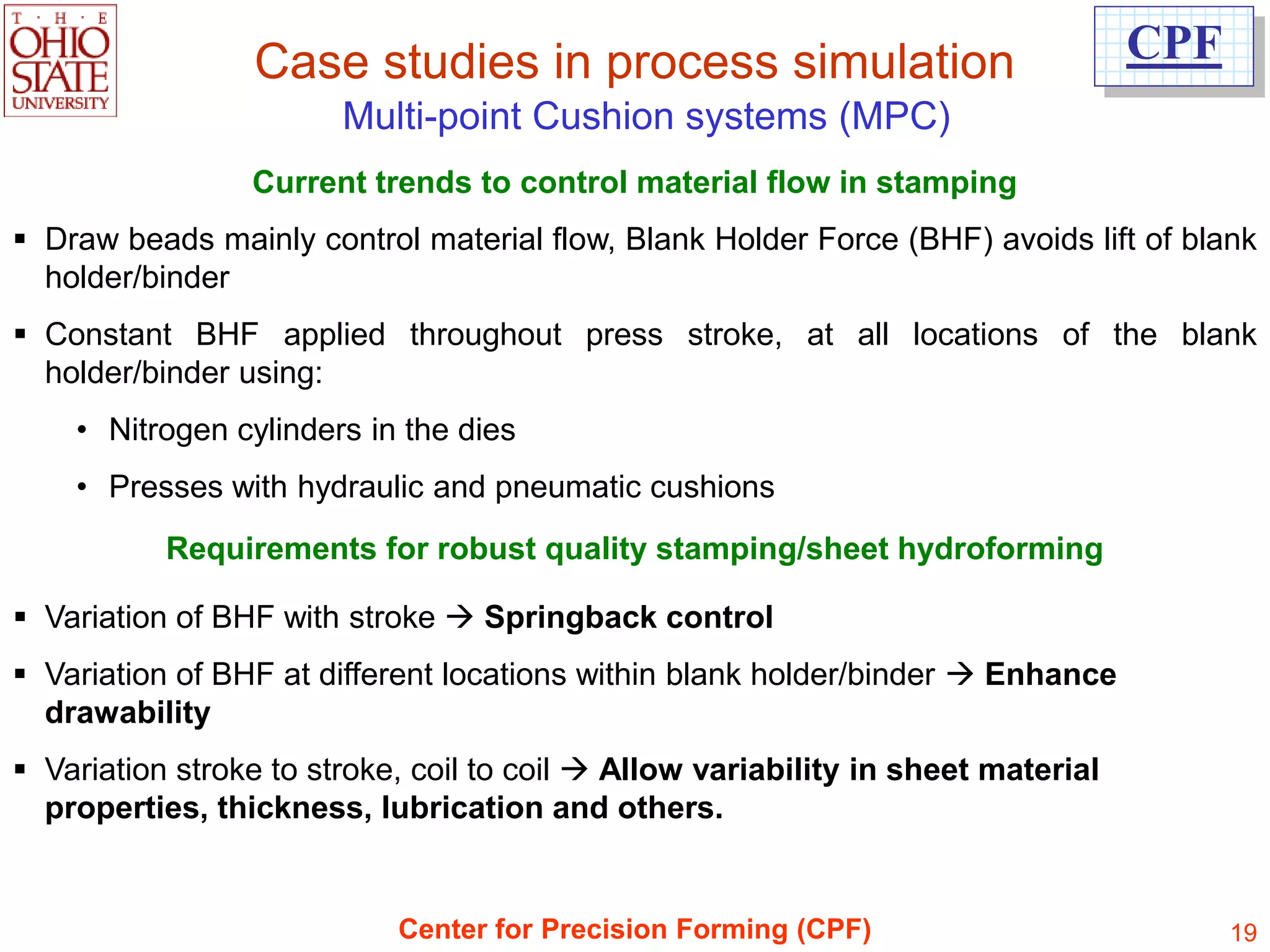
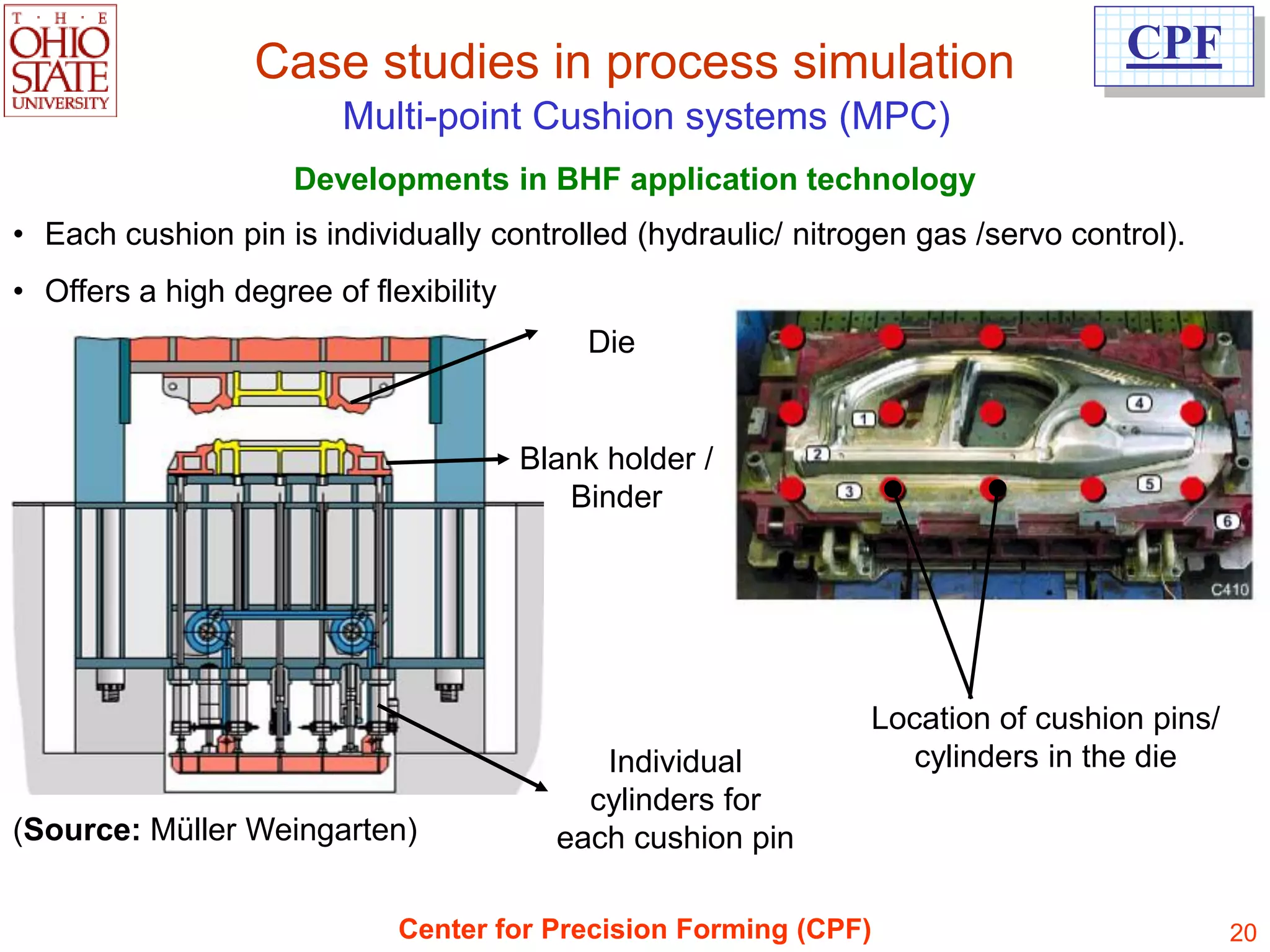
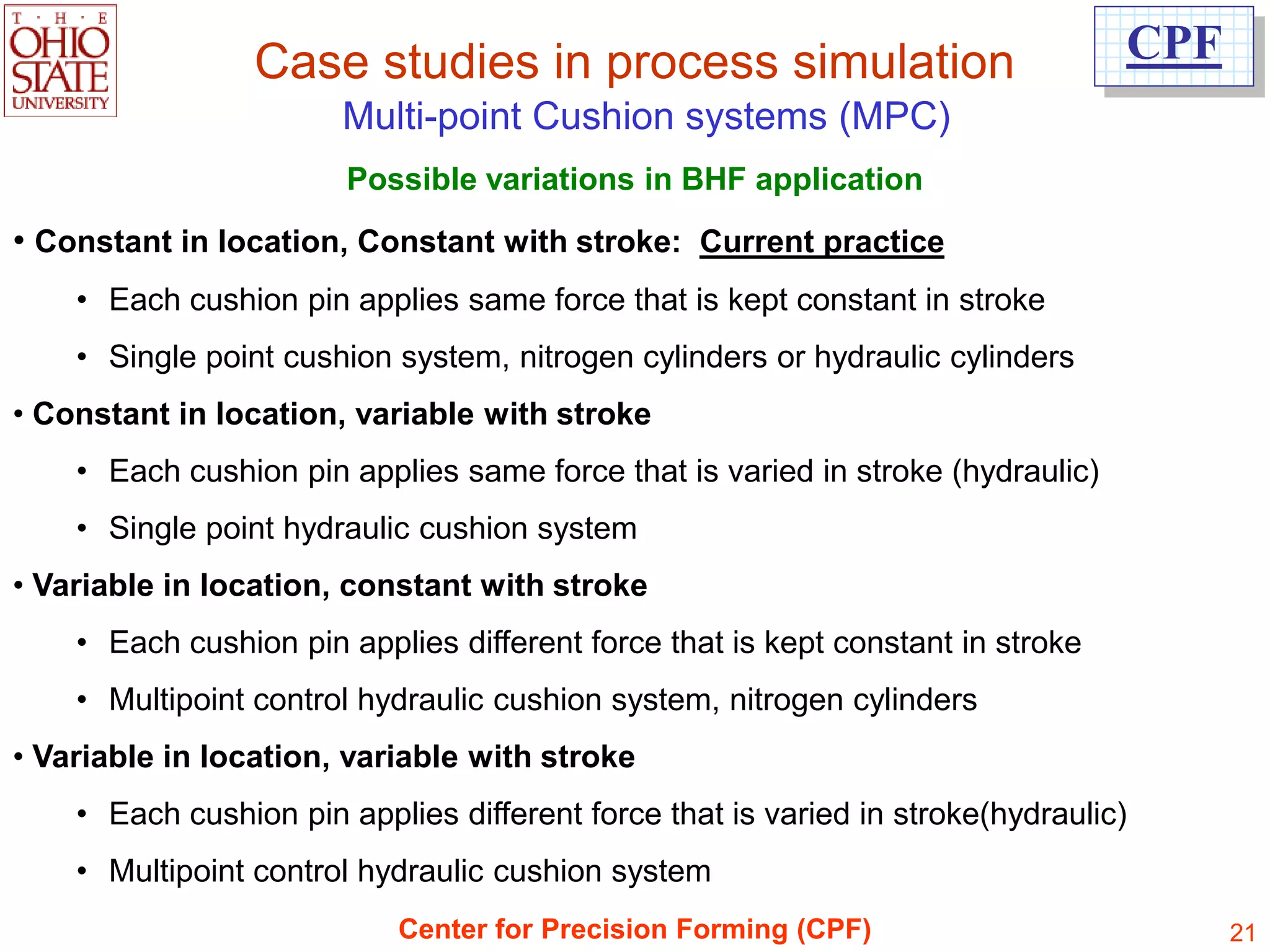
Multi-point control (MPC) die-cushion systems offer high flexibility in process
control, resulting in considerable improvement in formability. MPC systems
demonstrate good potential in forming light weight/high strength materials.
Reliable flow stress data at elevated temperature is required as an input for
accurate FE simulation of the warm forming process. Considerable research on
warm forming process and its application to production is in progress.
Intelligent use of process modeling saves time & costs and increases precision of
formed parts.
Center for Precision Forming (CPF) 41](https://image.slidesharecdn.com/simulationforforming-121213222146-phpapp01/75/Simulation-for-forming-41-2048.jpg)

The document discusses simulation and optimization of metal forming processes. It describes the Center for Precision Forming (CPF) and its work determining sheet material properties through bulge testing, evaluating stamping lubricants using tests like deep drawing, and simulating processes like multi-point cushion systems. CPF uses finite element analysis and experiments to optimize blank holder forces in multi-point cushions and validate simulations. Future work may adjust forces in production to compensate for material variability.