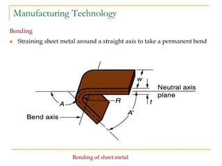
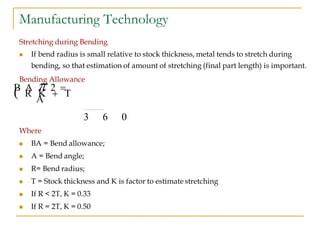
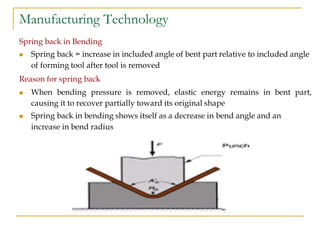
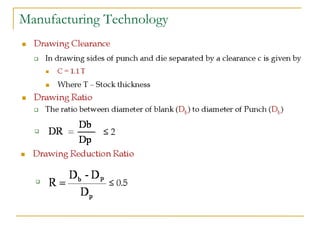
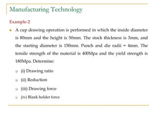
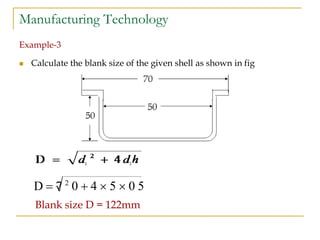
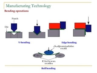
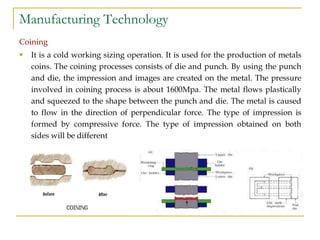
This document provides an overview of sheet metal forming processes. It discusses various sheet metal operations including cutting (shearing) operations like punching, blanking, and trimming as well as forming operations like bending, drawing, and squeezing. Bending operations including V-bending and edge bending are described. Drawing operations for forming hollow shapes are also covered along with squeezing processes like embossing and coining.
Fundamentals of Metal cutting and Machining Processes
MACHINING OPERATIONS AND MACHINING TOOLS
Turning and Related Operations
Drilling and Related Operations
Milling
Machining Centers and Turning Centers
Other Machining Operations
High Speed Machining
Sheet metal characteristics – shearing, bending and drawing operations – Stretch forming operations – Formability of sheet metal – Test methods –special forming processes-Working principle and applications – Hydro forming – Rubber pad forming – Metal spinning– Introduction of Explosive forming, magnetic pulse forming, peen forming, Super plastic forming – Micro forming.
sheet metal work ,die and punch.
it is generally useful for sheet metal operation.terminology of die and punch, types of die,types of punch,cutting force,method of reducing cutting force
This presentation will help to gain all essential and industrial knowledge related to sheet metal operations, design of sheet metal product, common sheet metal materials.
Ethnobotany and Ethnopharmacology:
Ethnobotany in herbal drug evaluation,
Impact of Ethnobotany in traditional medicine,
New development in herbals,
Bio-prospecting tools for drug discovery,
Role of Ethnopharmacology in drug evaluation,
Reverse Pharmacology.
How to Split Bills in the Odoo 17 POS ModuleCeline George
Bills have a main role in point of sale procedure. It will help to track sales, handling payments and giving receipts to customers. Bill splitting also has an important role in POS. For example, If some friends come together for dinner and if they want to divide the bill then it is possible by POS bill splitting. This slide will show how to split bills in odoo 17 POS.
Synthetic Fiber Construction in lab .pptxPavel ( NSTU)
Synthetic fiber production is a fascinating and complex field that blends chemistry, engineering, and environmental science. By understanding these aspects, students can gain a comprehensive view of synthetic fiber production, its impact on society and the environment, and the potential for future innovations. Synthetic fibers play a crucial role in modern society, impacting various aspects of daily life, industry, and the environment. ynthetic fibers are integral to modern life, offering a range of benefits from cost-effectiveness and versatility to innovative applications and performance characteristics. While they pose environmental challenges, ongoing research and development aim to create more sustainable and eco-friendly alternatives. Understanding the importance of synthetic fibers helps in appreciating their role in the economy, industry, and daily life, while also emphasizing the need for sustainable practices and innovation.
Unit 8 - Information and Communication Technology (Paper I).pdfThiyagu K
This slides describes the basic concepts of ICT, basics of Email, Emerging Technology and Digital Initiatives in Education. This presentations aligns with the UGC Paper I syllabus.
Students, digital devices and success - Andreas Schleicher - 27 May 2024..pptxEduSkills OECD
Andreas Schleicher presents at the OECD webinar ‘Digital devices in schools: detrimental distraction or secret to success?’ on 27 May 2024. The presentation was based on findings from PISA 2022 results and the webinar helped launch the PISA in Focus ‘Managing screen time: How to protect and equip students against distraction’ https://www.oecd-ilibrary.org/education/managing-screen-time_7c225af4-en and the OECD Education Policy Perspective ‘Students, digital devices and success’ can be found here - https://oe.cd/il/5yV
How to Create Map Views in the Odoo 17 ERPCeline George
The map views are useful for providing a geographical representation of data. They allow users to visualize and analyze the data in a more intuitive manner.
Instructions for Submissions thorugh G- Classroom.pptxJheel Barad
This presentation provides a briefing on how to upload submissions and documents in Google Classroom. It was prepared as part of an orientation for new Sainik School in-service teacher trainees. As a training officer, my goal is to ensure that you are comfortable and proficient with this essential tool for managing assignments and fostering student engagement.
2024.06.01 Introducing a competency framework for languag learning materials ...Sandy Millin
http://sandymillin.wordpress.com/iateflwebinar2024
Published classroom materials form the basis of syllabuses, drive teacher professional development, and have a potentially huge influence on learners, teachers and education systems. All teachers also create their own materials, whether a few sentences on a blackboard, a highly-structured fully-realised online course, or anything in between. Despite this, the knowledge and skills needed to create effective language learning materials are rarely part of teacher training, and are mostly learnt by trial and error.
Knowledge and skills frameworks, generally called competency frameworks, for ELT teachers, trainers and managers have existed for a few years now. However, until I created one for my MA dissertation, there wasn’t one drawing together what we need to know and do to be able to effectively produce language learning materials.
This webinar will introduce you to my framework, highlighting the key competencies I identified from my research. It will also show how anybody involved in language teaching (any language, not just English!), teacher training, managing schools or developing language learning materials can benefit from using the framework.
2. Manufacturing Technology
Sheet Metal
Introduction
Sheet metal is a metal formed into thin and flat pieces. It is one of
the fundamental forms used in metalworking, and can be cut and
bent into a variety of different shapes.
Countless everyday objects are constructed by this material.
Thicknesses can vary significantly, although extremely thin sheets
are considered as foil or leaf, and sheets thicker than 6 mm (0.25 in)
are considered as plate.
3. Manufacturing Technology
Sheet Metal Processing
The raw material for sheet metal manufacturing processes is the output
of the rolling process.
Typically, sheets of metal are sold as flat, rectangular sheets of
standard size.
If the sheets are thin and very long, they may be in the form of rolls.
Therefore the first step in any sheet metal process is to cut the correct
shape and sized blank from larger sheet.
4. Manufacturing Technology
Sheet Metal Working
Performing Cutting and forming operations on relatively thin sheets
of metal
Thickness of sheet metal = 0.4 mm to 6 mm
Thickness of plate stock > 6 mm
Operations usually performed as cold working
5. Manufacturing Technology
Sheet Metal operations
Introduction
Sheet metal forming is a grouping of many complementary
processes that are used to form sheet metal parts.
One or more of these processes is used to take a flat sheet of ductile
metal, and mechanically apply deformation forces that alter the
shape of the material. Before deciding on the processes, one should
determine whether a particular sheet metal can be formed into the
desired shape without failure.
The sheet metal operations done on a press may be grouped into
two categories, cutting (shearing) operations and forming
operations.
7. Manufacturing Technology
Sheet Metal operations
The art of sheet metal lies in the making of different shapes by
adopting different operations. The major types of operations are
given below
Shearing (Cutting)
Bending
Drawing
Squeezing
8. Manufacturing Technology
Sheet Metal operations
Shearing
Cutting to separate large sheets; or cut part perimeters or make
holes in sheets
Bending
Straining sheet around a straight axis
Drawing
Forming of sheet into convex or concave shapes
Squeezing
Forming of sheet by gripping and pressing firmly – Coining &
Embossing
9. Manufacturing Technology
Shearing (Cutting)
Shearing of sheet metal between two sharp cutting edges
A. Just before the punch contacts work
B. Punch begins to push into work,
causing plastic deformation
C. Punch compresses and penetrates into
work causing a smooth cut surface
D. Fracture is initiated at the opposing
cutting edges which separates the sheet
11. Manufacturing Technology
Metal on inside of neutral plane is compressed, while metal on outside of
neutral plane is stretched
Both compression and tensile elongation of the metal occur in bending
12. Manufacturing Technology
Types of Sheet metal Bending
V-bending- performed with a V - shaped die
Edge bending - performed with a wiping Die
V-Bending
For low production
Performed on a press brake
V-dies are simple and inexpensive
V-bending
14. Manufacturing Technology
Stretching during Bending
If bend radius is small relative to stock thickness, metal tends to stretch during
bending, so that estimation of amount of stretching (final part length) is important.
Bending Allowance
Where
BA = Bend allowance;
A = Bend angle;
R= Bend radius;
T = Stock thickness and K is factor to estimate stretching
If R < 2T, K = 0.33
If R = 2T, K = 0.50
3 6 0
B A 2
R K T
A
15. Manufacturing Technology
Bending Force
Maximum bending force estimated as follows
Where
F = Bending Force
TS = Tensile strength of sheet metal
W= Part width in direction of bend axis
D = Die opening dimension
T = Stock thickness and K is factor estimates bend force
For V-Bending- Kbf = 1.33
For Edge-Bending - Kbf = 0.33 or 0.50
D
K T W T 2
b f S
F
17. Manufacturing Technology
Bending Force Calculation
Example -1
A sheet-metal part 3mm thick and 20mm long is bent to an included angle of
60o and a bend radius of 7.5mm in a V-die. The die opening is 15mm. The
metal has tensile strength of 340 MPa. Compute the required force to bend the
part.
Solution
Bending force Required
D
K T W T 2
b f S
F
1 . 3 3 1 4 6
3 0 0 0 2
. 2 0 0F 5 4
0 . 0 1 5
The bending force required to bend the part is 5426.4 N
18. Manufacturing Technology
Spring back in Bending
Spring back = increase in included angle of bent part relative to included angle
of forming tool after tool is removed
Reason for spring back
When bending pressure is removed, elastic energy remains in bent part,
causing it to recover partially toward its original shape
Spring back in bending shows itself as a decrease in bend angle and an
increase in bend radius
19. Manufacturing Technology
1. During bending the work is forced t take the radius Rb and include
angle Ab of the bending tool (punch inv-bending)
2. After punch is removed the work springs back to radius R and angle A
Spring back
20. Manufacturing Technology
Spring back
When a plate is bent, using a bending tool, the plate initially
assumes the angle of the tool θ’. As the plate is removed from the
tool, it springs back to an angle θ’b less than the tool angle.
The spring back, Sb defined as follows
21. Manufacturing Technology
Drawing
Forming of sheet into convex or concave shapes
Sheet metal blank is positioned over die cavity and than punch pushed
metal in to opening
Products – Beverage cans, automobile body parts and ammunition shells
24. Manufacturing Technology
Holding force of the Blank
Where
Sy is the Yield Tensile strength of theblank
rp - Punch Radius or Die radius
25. Manufacturing Technology
Example-2
A cup drawing operation is performed in which the inside diameter
is 80mm and the height is 50mm. The stock thickness is 3mm, and
the starting diameter is 150mm. Punch and die radii = 4mm. The
tensile strength of the material is 400Mpa and the yield strength is
180Mpa. Determine:
(i) Drawing ratio
(ii) Reduction
(iii) Drawing force
(iv) Blank holder force
27. Manufacturing Technology
Blank Size Calculation
For final dimensions of drawn shape to be correct, starting blank
diameter Db must be correct.
Solve Db by setting starting sheet metal blank volume = final product
volume
To facilitate calculation, assume negligible thinning of part wall with
diameter d height h
d
h
28. Manufacturing Technology
The Size or Diameter of the blank is given by
Blank volume = Final product volume
D2/4 = d1
2/4 + d2h
D2 = d1
2 +4d2h
The Size or Diameter of the blank is
30. Manufacturing Technology
Sheet metal Process in detail
Cutting (Shearing) Operations
In this operation, the work piece is stressed beyond its ultimate strength. The
stresses caused in the metal by the applied forces will be shearing stresses. The
cutting operations include
Punching (Piercing)
Blanking
Trimming
Notching
Perforating
Slitting
Lancing
Parting
Shaving
Fine blanking
31. Manufacturing Technology
Shearing Operations
Punching (Piercing) It is a cutting operation by which various shaped
holes are made in sheet metal. Punching is similar to blanking except
that in punching, the hole is the desired product, the material punched
out to form the hole being waste.
Blanking: Blanking is the operation of cutting a flat shape sheet metal.
The article punched out is called the blank and is the required product
of the operation. The hole and metal left behind is discarded as waste.
Notching: This is cutting operation by which metal pieces are cut from
the edge of a sheet, strip or blank.
32. Manufacturing Technology
Perforating: This is a process by which multiple holes which are very
small and close together are cut in flat work material.
Slitting: It refers to the operation of making incomplete holes in a
work piece.
Lancing: This is a cutting operation in which a hole is partially cut and
then one side is bent down to form a sort of tab. Since no metal is
actually removed, there will be no scrap.
Parting: Parting involves cutting a sheet metal strip by a punch with
two cutting edges that match the opposite sides of the blank.
33. Manufacturing Technology
Shaving: The edge of blanked parts is generally rough, uneven and
un-square. Accurate dimensions of the part are obtained by removing
a thin strip of metal along the edges.
Fine blanking: Fine blanking is a operation used to blank sheet metal
parts with close tolerances and smooth, straight edges in one step.
Trimming: This operation consists of cutting unwanted excess
material from the periphery of previously formed components.
35. Schematic illustrations of shaving on a sheared edge.
(a) Shaving a sheared edge. (b) Shearing and shaving,
combined in one stroke.
Fine blanking
Manufacturing Technology
Shearing Operations
Shaving Trimming
36. Manufacturing Technology
Shearing Dies
Because the formability of a sheared part can be influenced by the
quality of its sheared edges, clearance control is important.
In practice, clearances usually range between 2% and 8% of the
sheet’s thickness; generally, the thicker the sheet, the larger is the
clearance (as much as 10%). However, the smaller the clearance, the
better is the quality of the edge.
37. Manufacturing Technology
Punch and Die Shapes
As the surfaces of the punch and die are flat; thus, the punch force builds up
rapidly during shearing, because the entire thickness of the sheet is sheared
at the same time. However, the area being sheared at any moment can be
controlled by beveling the punch and die surfaces, as shown in the following
Figure. This geometry is particularly suitable for shearing thick blanks,
because it reduces the total shearing force.
Examples of the use of shear angles on punches and dies
38. Manufacturing Technology
Types of Shearing Dies
Progressive Dies: Parts requiring multiple operations, such as punching,
blanking and notching are made at high production rates in progressive
dies. The sheet metal is fed through a coil strip and a different operation is
performed at the same station with each stroke of a series of punches.
Compound Dies: Several operations on the same strip may be performed in
one stroke with a compound die in one station. These operations are
usually limited to relatively simple shearing because they are somewhat
slow and the dies are more expensive than those for individual shearing
operations.
Transfer Dies (Combination Dies): In a transfer die setup, the sheet metal
undergoes different operations at different stations, which are arranged
along a straight line or a circular path. After each operation, the part is
transfer to the next operation for additional operations.
39. Manufacturing Technology
Progressive Die
(a) Schematic illustration of making a washer in a progressive die.
(b) Forming of the top piece of an aerosol spray can in a progressive die.
40. Manufacturing Technology
Compound Die
(a) (b)
Schematic illustrations: (a) before and (b) after blanking a common washer in a compound die.
Note the separate movements of the die (for blanking) and the punch (for punching the hole in the washer).
42. Manufacturing Technology
Forming Operations
In this operation, the stresses are below the ultimate strength of the
metal. In this operation, there is no cutting of the metal but only the
contour of the work piece is changed to get the desired product. The
forming operations include
Bending
Drawing
Squeezing
43. Manufacturing Technology
Bending: In this operation, the material in the form of flat sheet or
strip, is uniformly strained around a linear axis which lies in the
neutral plane and perpendicular to the lengthwise direction of the
sheet or metal
Drawing : This is a process of a forming a flat work piece into a
hollow shape by means of a punch, which causes the blank to flow
into die cavity.
Squeezing: Under this operation, the metal is caused to flow to all
portions of a die cavity under the action of compressive forces.
47. Manufacturing Technology
Embossing
This is the process of making raised or projected design on the surface of
the metal with its corresponding relief on the other side. This operation
includes drawing and bending. It uses a die set which consists of die and
punch with desired shape. This operation requires less force compared with
coining process. It is very useful for producing nameplates tags and designs
on the metal.
48. Manufacturing Technology
Coining
It is a cold working sizing operation. It is used for the production of metals
coins. The coining processes consists of die and punch. By using the punch
and die, the impression and images are created on the metal. The pressure
involved in coining process is about 1600Mpa. The metal flows plastically
and squeezed to the shape between the punch and die. The metal is caused
to flow in the direction of perpendicular force. The type of impression is
formed by compressive force. The type of impression obtained on both
sides will be different
49. Manufacturing Technology
Flanging
Flanging is a process of bending the edges of sheet metals to 90o
Shrink flanging – subjected to compressive hoop stress.
Stretch flanging –subjected to tensile stresses
50. Manufacturing Technology
Dimpling:
First hole is punched and expanded into a flange
Flanges can be produced by piercing with shaped punch
When bend angle < 90 degrees as in fitting conical ends its called
flanging
51. Manufacturing Technology
Tube Forming or Bending
Bending and forming tubes and other hollow sections require
special tooling to avoid buckling and folding. The oldest method of
bending a tube or pipe is to pack the inside with loose particles,
commonly used sand and bend the part in a suitable fixture.
This technique prevents the tube from buckling. After the tube has
been bent, the sand is shaken out. Tubes can also be plugged with
various flexible internal mandrels.
52. Manufacturing Technology
Tube Forming
Methods of bending tubes. Internal mandrels, or the filling of tubes with particulate materials such as
sand are often necessary to prevent collapse of the tubes during bending .Solid rods and structural
shapes can also be bent by these techniques
53. Manufacturing Technology
Stretch Forming
In stretch forming, the sheet metal is clamped around its edges and
stretched over a die or form block, which moves upward,
downward or sideways, depending on the particular machine.
Stretch forming is used primarily to make aircraft-wing skin panel,
automobile door panels and window frames.
55. Manufacturing Technology
Press break forming
Sheet metal or plate can be bent easily with simple fixtures using a
press. Long and relatively narrow pieces are usually bent in a press
break. This machine utilizes long dies in a mechanical or hydraulic
press and is suitable for small production runs. The tooling is simple
and adaptable to a wide variety of shapes
57. Manufacturing Technology
Beading
In beading the edge of the sheet metal is bent into the cavity of a die.
The bead gives stiffness to the part by increasing the moment on
inertia of the edges. Also, it improves the appearance of the part and
eliminates exposed sharp edges
59. Manufacturing Technology
Roll forming
For bending continuous lengths of sheet metal and for large
production runs, roll forming is used. The metal strip is bent in
stages by passing it through a series of rolls.
Roll-forming process
60. Manufacturing Technology
Stages in roll forming
Stages in roll forming of a sheet-metal door frame. In Stage 6, the rolls may be shaped as in A or B.
61. Manufacturing Technology
Bulging
The basic forming process of bulging involves placing tabular,
conical or curvilinear part into a split-female die and expanding it
with, say, a polyurethane plug. The punch is then retracted, the plug
returns to its original shape and the part is removed by opening the
dies.
62. Manufacturing Technology
Bulging
(a) Bulging of a tubular part with a flexible plug. Water pitchers can be made by this method. (b)
Production of fittings for plumbing by expanding tubular blanks with internal pressure. The bottom of
the piece is then punched out to produce a “T.” (c) Manufacturing ofBellows.
63. Manufacturing Technology
Rubber Forming
In rubber forming , one of the dies in a set is made of flexible
Polyurethanes are used
material, such as a rubber or polyurethane membrane.
widely because of their resistance to
abrasion, long fatigue life and resistance to damage by burrs or
sharp edges of the sheet blank. In bending and embossing sheet
metal by the rubber forming method, as shown in the following
Figure, the female die is replaced with a rubber pad. Parts can also
be formed with laminated sheets of various nonmetallic material or
coatings.
65. Manufacturing Technology
Hydro forming Process
In hydro forming or fluid forming process, the pressure over the
rubber membrane is controlled throughout the forming cycle, with
maximum pressure reaching 100 MPa (15000 psi). This procedure
allows close control of the part during forming to prevent wrinkling
or tearing.
66. Manufacturing Technology
Hydro forming Process
The hydroform (or fluid forming) process. Note that, in contrast to the ordinary deep-drawing process, the
pressure in the dome forces the cup walls against the punch. The cup travels with the punch; in this way,
deep drawability is improved.
67. Manufacturing Technology
Rubber forming and Hydro-forming processes have the following
Advantages:
Low tooling cost
Flexibility and ease of operation
Low die wear
No damage to the surface of the sheet and
Capability to form complex shapes.
68. Manufacturing Technology
Tube-Hydro forming Process
In tube hydro forming, steel or other metal tubing is formed in a die
and pressurized by a fluid. This procedure can form simple tubes or
it can form intricate hollow tubes as shown in the following Figure.
Applications of tube-hydro formed parts include automotive
exhaust and structural components.
69. Manufacturing Technology
Tube-Hydro forming Process
(a) Schematic illustration of the tube-hydroforming process. (b) Example of tube-hydroformed
parts. Automotive exhaust and structural components, bicycle frames, and hydraulic and
pneumatic fittings are produced through tubehydroforming.
70. Manufacturing Technology
Explosive Forming Process
Explosive energy used as metal forming
Sheet-metal blank is clamped over a die
Assembly is immersed in a tank with water
Rapid conversion of explosive charge into gas generates a shock
wave. The pressure of this wave is sufficient to form sheet metals
72. Manufacturing Technology
Diffusion Bonding and Super plastic Forming
Types of structures made by diffusion bonding and superplastic forming of
sheet metal. Such structures have a high stiffness-to-weightratio.
73. Manufacturing Technology
Super plastic Forming
Advantages
Lower strength is required and less tooling costs
Complex shapes with close tolerances can be made
Weight and material savings
Little or no residual stress occurs in the formed parts
Disadvantages
Materials must not be super elastic at service temperatures
Longer cycle times
74. Manufacturing Technology
Deep Drawing Processes
Deep Drawing
Drawing operation is the process of forming a flat piece of material
(blank) into a hollow shape by means of a punch, which causes the
blank to flow into the die-cavity. Round sheet metal block is placed
over a circular die opening and held in a place with blank holder &
punch forces down into the die cavity. Wrinkling occurs at the
edges.
Shallow drawing: depth of formed cup D/2
Deep or moderate drawing: depth of formed cup > D/2
75. Manufacturing Technology
Deep Drawing
(a) deep-drawing process on a circular sheet-metal blank. The stripper ring facilitates the
removal of the formed cup from the punch. (b) Process variables in deep drawing. Except
for the punch force, F, all the parameters indicated in the figure are independent variables.
76. Manufacturing Technology
Examples of drawing operations
(a) pure drawing and (b) pure stretching. The bead prevents the sheet metal from flowing freely into the die
cavity. (c) Possibility of wrinkling in the unsupported region of a sheet in drawing.
77. Manufacturing Technology
Ironing Process
If the thickness of the sheet as it enters the die cavity is more than
the clearance between the punch and the die, the thickness will have
to be reduced; this effect is known as ironing. Ironing produces a
cup with constant wall thickness thus, the smaller the clearance, the
greater is the amount of ironing.
Schematic illustration of the ironing process. Note that the cup wall is thinner than its bottom. All
beverage cans without seams (known as two-piece cans) are ironed, generally in three steps, after
being deep drawn into a cup. (Cans with separate tops and bottoms are known as three-piececans.)
78. Manufacturing Technology
Redrawing Operations
Containers or shells that are too difficult to draw in one operation
are generally redrawn. In reverse redrawing, shown in following
Figure, the metal is subjected to bending in the direction opposite to
its original bending configuration. This reversal in bending results
in strain softening. This operation requires lower forces than direct
redrawing and the material behaves in a more ductile manner
79. Manufacturing Technology
Redrawing Operations
Reducing the diameter of drawn cups by redrawing operations: (a) conventional redrawing and (b)
reverse redrawing. Small-diameter deep containers undergo many drawing and redrawing
operations.
81. Manufacturing Technology
Steps in Manufacturing an Aluminium Can
The metal-forming processes involved in manufacturing a two-piece aluminium
beverage can
83. Manufacturing Technology
Press for Sheet Metal
Press selection for sheet metal forming operations depends on
several factors:
Type of forming operation, and dies and tooling required
Size and shape of work pieces
Length of stroke of the slide, stroke per minute, speed and shut
height (distance from the top of the bed to the bottom of the slide,
with the stroke down)
Number of slides (single action, double action and triple action)
Maximum force required (press capacity, tonnage rating)
Type of controls
Die changing features
Safety features
84. Manufacturing Technology
TYPES OF PRESS FRAMES
Schematic illustration of types of press frames for sheet- forming operations. Each type has
its own characteristics of stiffness, capacity, and accessibility.
85. Manufacturing Technology
Sheet and Plate Metal Products
Sheet and plate metal parts for consumer and industrial products
such as
Automobiles and trucks
Airplanes
Railway cars and locomotives
Farm and construction equipment
Small and large appliances
Office furniture
Computers and office equipment
86. Manufacturing Technology
Advantages of Sheet Metal Parts
High strength
Good dimensional accuracy
Good surface finish
Relatively low cost
For large quantities, economical mass production operations are
available
87. Manufacturing Technology
Tools and Accessories
Marking and measuring tools
Steel Rule
It is used to set out dimensions.
Try Square
Try square is used for making and testing angles of 90degree
Scriber
It used to scribe or mark lines on metal work pieces.
Divider
This is used for marking circles, arcs, laying out perpendicular
lines, bisecting lines, etc
89. Manufacturing Technology
Cutting Tools
Straight snip
They have straight jaws and used for straight line cutting.
Curved snip
They have curved blades for making circular cuts.
Curved snipStraight snip
90. Manufacturing Technology
Striking Tools
Mallet - It is wooden-headed hammer of round or rectangular cross
section. The striking face is made flat to the work. A mallet is used
to give light blows to the Sheet metal in bending and finishing.
Types of Mallets