Downloaded 263 times
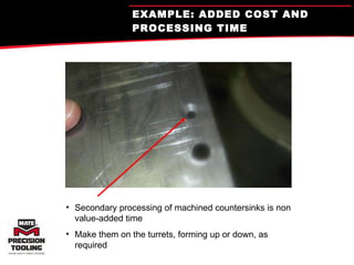

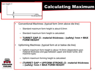


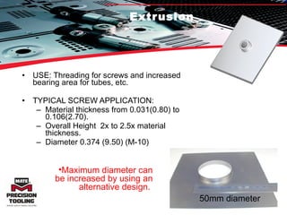
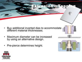

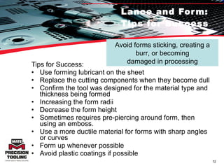
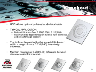


The document discusses forming solutions for increasing efficiency in manufacturing operations. It provides an overview of why forming is useful, examples of how it can replace or improve upon other processes like punching, and basics of forming like considerations for setup and maximum form heights. Key advantages of forming include increased efficiency, expanded capabilities, and elimination of secondary operations.


![B7 PROGRESSSSSS [Autosaved] (1).pptx](https://cdn.slidesharecdn.com/ss_thumbnails/b7progressssssautosaved1-230427045414-1879625e-thumbnail.jpg?width=640&height=640&fit=bounds)


