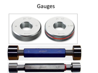
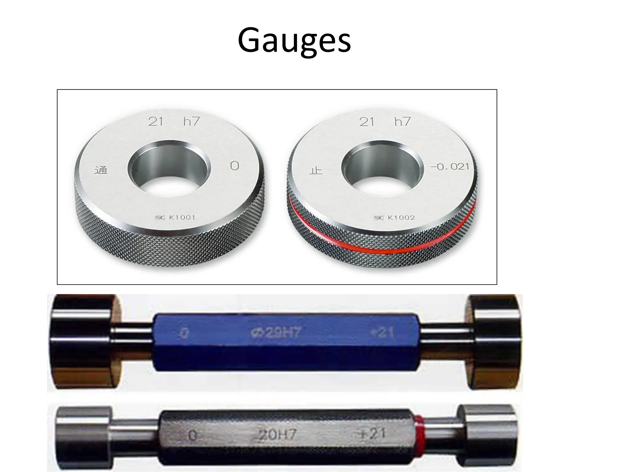
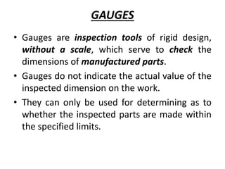
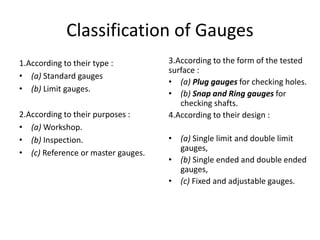
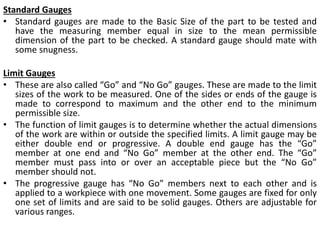
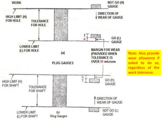
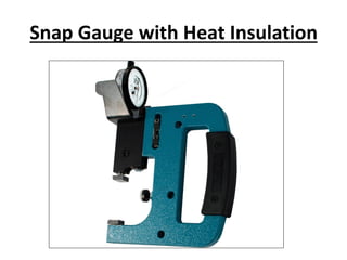
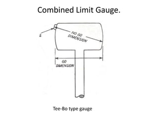
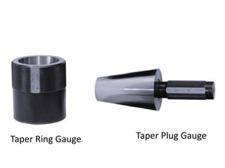
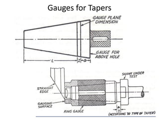
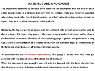
Gauges are inspection tools used to check the dimensions of manufactured parts without providing an actual measurement. There are various types of gauges classified by purpose, design, and what type of surface they check. Standard gauges match the nominal size while limit gauges check if a part is within the minimum and maximum limits. Other types include plug gauges for holes, snap gauges for shafts, and adjustable gauges. Gauges are also classified as working, inspection, or reference gauges based on their intended use. Proper gauge design and application is important to ensure accurate inspection of parts.


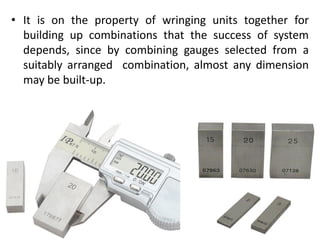

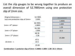
![Selecting slip gauges for required
dimension.
• Let us say that the dimension to be arranged is 58.975 mm.
• Always start with the last decimal place e.g.. here it is 0.005 mm
and for this 1.005 mm slip gauge is selected.
• Now dimension left is 58.975-1.005 =57.970mm.
• Take second decimal place ; and for it select 1.47 mm slip gauge.
• Therefore. the remainder is 57.970 - 1.47 =56.500 mm.
• [Note : One could have selected 1.07 mm piece also. but that way
we would have been left with 56.900 and for it we need another
1.4 mm piece. Our aim should be to choose minimum number of
slip gauges for a given dimension.]
• Next for 56.500 mm, we choose 6.500 mm piece and finally 50.000
mm piece.
• Thus, we have 50.000+6.550+ 1.47+1.005 =58.975mm.
• All these four slip gauges are wrung properly to get required
dimension.](https://image.slidesharecdn.com/gaugesppt-240314065039-5d7faa9d/85/Gauges-ppt-pdf-52-320.jpg)