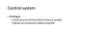
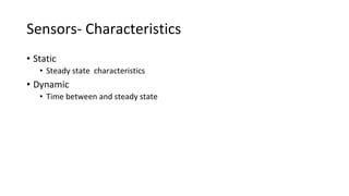
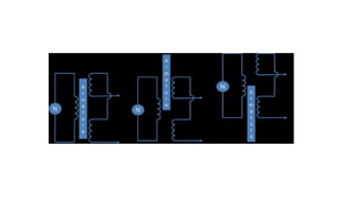
Mechatronic design
Design process
• Need
• Analysis
• Preparation of specification
• Conceptual stage
• Selecting a solution
• Production (prototype)
• Wkg dwg
Modelling systems
• Response not instantaneous
• Relating output with input
• Steady state and transient
Control systems
• Open loop
• Closed loop
MECHATRONICS
Session 5
BOOKS
W. BOLTON, MAHALIK, Rajput. R.K,
Closed loop
• Basic elements
• Comparison element
• Control element
• Correction element
• Process element
• Measurement element
Control system
• Analogue
• Continuous fun of time which measures variable
• Signals are converted to digital using ADC
Ctrl sys
• Digital
• Sequence of ON/OFF signals
• Converted to analog using DAC
Example
Shaft speed control
Washing machine
Auto focus camera
• Sensors
• Transducer
• Smart Sensor
sensors
• Classification
• Displacement
• Proximity
• Velocity
• Force
• Fluid pressure
• Temperature
• Light sensors
Sensors- Characteristics
• Static
• Steady state characteristics
• Dynamic
• Time between and steady state
Terminology
• Range and Span
• Accuracy
• Sensitivity
• Error
• Hysteresis
• Non linearity
• Repeatability
• Dead band
• Resolution
sensors
displ proximity velocity flow temp light
Static Characteristics
• Sensitivity
• Ratio of change in output to change in input
• Output per unit input
• Also used to indicate factors affecting sensors
• Linearity
• Constancy of output to input ratio
y= cx
• Range
• Diff between max and min value measured
• Accuracy
• Difference between measured and actual value
• It is dimensionless value
• Repeatability
• Difference in value between two measurement under same conditions
• Resolution
• Minimum change of input detected at output of sensing system
• No of measurement with in a range
• Output
• In any form mechanical, electrical ( voltage o/p)
Dynamic characteristics
• Response time
• Time to respond (95% of inp value steady state)
• Time constant
• Inertia of sensor ( 63.2 % of steady state)
• Rise time
• Time for rise of output (10% -90% of steady state)
• Settling time
• Time for output to settle ( 2% of steady state)
Measurement system
system sensor transducer Display
SENSORS
TYPE SENSOR
NAME
MAT
USED
APPLICATION
Level Measurement
• Direct Methods
• 1.Bob and tape method
• 2.Sight glass method
• 3.Float type method
• Indirect Methods
• 1.Pressure gauge method
• 2.Manometric level method
• 3.Diaphragm box method
• 4.Air trap method
LVDT
RVDT
OUTPUT (LVDT RVDT)
EDDY CURRENT SENSORS
• Coil carrying current produces mag field
• Eddy currents are induced when is metal close,
• Eventually producing mag field, distorting the field
produced by current carrying coil
• It triggers a switch at threshold
• Used in non magnetic ,conductive environment
• Highly reliable and sensitive
Position and Speed Measurement
• By position measurement we may need to check
• If a part is reached a predefined location or not
• The total displacement of the part
• Both the measurements are again divided in two types
• Linear
• Angular/ Rotary
Capacitive
Applications
• These sensors are primarily used in the control systems with a
feedback loop to ensure that the moving member or component
reaches its commanded position.
• machine-tool controls, elevators, liquid-level assemblies, forklift
trucks, automobile throttle controls
• woodworking machinery, printing, spraying, robotics
Applications
• Feed hopper level monitoring
• Small vessel pump control
• Grease level monitoring
• Assembly line testing o to test assembled parts for uniformity,
thickness or other design features
• to analyze and optimize the rotation of spindles in various machine
tools such as surface grinders, lathes, milling machines, and air
bearing
Proximity Sensors
• Activating a switch by a presence of object
• Reed switch
• Mag contact sealed in glass tube
• Switch close when mag brought near
• Used in tachometers , as sensors in pneumatic eqpts
• Microswitch
• Small electrical requiring small force to close
• Detects presence of object by its weight
• Lever , roller , cam operated
Reed switch & photo detector
Eddy current
Application
• Eddy current proximity sensors are used to detect non-magnetic but
conductive materials. They comprise of a coil, an oscillator, a detector and
a triggering circuit
• Automation requiring precise location
• Machine tool monitoring
• Final assembly of precision equipment such as disk drives
• Measuring the dynamics of a continuously moving target, such as a
vibrating element,
• Drive shaft monitoring
• Vibration measurements
Inductive
• the coil, oscillator, detection circuit and output circuit. An alternating
current is supplied to the coil which generates a magnetic field.
When, a metal object comes closer to the end of the coil, inductance
of the coil changes.
• Applications of inductive proximity switches
• Industrial automation: counting of products during production or
transfer
• Security: detection of metal objects, arms, land mines
Hall effect
• Observed and discovered by Hall in 1880s
• Beam of charged particles deflects when passes through mag field
• Two fields – electric and magnetic field
• Magnetic field due to pot diff being applied
• Electric field due to charge separation
• Two types linear and threshold
Hall effect sensor
Hall effect sensor
Applications
• Measurement of spool position in a wide range of servo valve applications
• To provide displacement feedback for hydraulic cylinders
• To control weight and thickness of medicinal products viz. tablets or pills
• For automatic inspection of final dimensions of products being packed for
dispatch
• To measure distance between the approaching metals during Friction
welding process
• To continuously monitor fluid level as part of leak detection system
• To detect the number of currency bills dispensed by an ATM
Strain Gauge
• The Gauge Factor for metallic strain gauges is typically around 2
Strain gauge
Applications
• Strain gauges are widely used in experimental stress analysis and
diagnosis on machines and failure analysis
• bending and deflection measurement, compression and tension
measurement and strain measurement.
• force measurement in machine tools
• impact sensors in aerospace vehicles
Optical encoder
• Absolute and incremental encoder
• Senses both speed and direction of rotation
• Detected by no of pulses captured by sensor
• Three concentric tracks
• Home , direction and speed
• Output in terms of binary num of digits (000, 011)
• Sequential output from slots with 10 tracks
• 10 tracks give 10 bits = 210 = 1024 positions
• Resolution of 360/10= 0.350
Encoder
SPEED MEASUREMENT
• Speed measurements can be obtained by taking consecutive position
measurements at known time intervals and computing the ‘time
rate’of change of the position values.
• Tachometer is an example of speed sensor which does the same
thing for a rotating shaft.
photoemitter-detector
piezoelectric
• Generates electric charge when stretched or compressed with +ve & -
ve charge in opp faces
• Ionic crystals , charge distribution when stretched or compressed
• Used in measurement of pressure , force , acceleration
Tactile sensor
Tactile sensor
• A pressure sensor
• PVDF – polyvinylidene fluoride( piezo)
• Touch display, fingertip of robot hands
• Two layers of PVDF separated by soft film
• When pressure is applied on upper layer of PVDF vibrations are
affected , changing output voltage

unit 1.1.pptx

  • 1.
  • 2.
    Design process • Need •Analysis • Preparation of specification • Conceptual stage • Selecting a solution • Production (prototype) • Wkg dwg
  • 4.
    Modelling systems • Responsenot instantaneous • Relating output with input • Steady state and transient
  • 6.
    Control systems • Openloop • Closed loop
  • 7.
  • 8.
    Closed loop • Basicelements • Comparison element • Control element • Correction element • Process element • Measurement element
  • 9.
    Control system • Analogue •Continuous fun of time which measures variable • Signals are converted to digital using ADC
  • 10.
    Ctrl sys • Digital •Sequence of ON/OFF signals • Converted to analog using DAC
  • 11.
  • 12.
  • 13.
  • 14.
  • 15.
  • 16.
    sensors • Classification • Displacement •Proximity • Velocity • Force • Fluid pressure • Temperature • Light sensors
  • 17.
    Sensors- Characteristics • Static •Steady state characteristics • Dynamic • Time between and steady state
  • 18.
    Terminology • Range andSpan • Accuracy • Sensitivity • Error • Hysteresis • Non linearity • Repeatability • Dead band • Resolution
  • 19.
  • 20.
    Static Characteristics • Sensitivity •Ratio of change in output to change in input • Output per unit input • Also used to indicate factors affecting sensors
  • 21.
    • Linearity • Constancyof output to input ratio y= cx • Range • Diff between max and min value measured
  • 22.
    • Accuracy • Differencebetween measured and actual value • It is dimensionless value • Repeatability • Difference in value between two measurement under same conditions
  • 23.
    • Resolution • Minimumchange of input detected at output of sensing system • No of measurement with in a range • Output • In any form mechanical, electrical ( voltage o/p)
  • 25.
    Dynamic characteristics • Responsetime • Time to respond (95% of inp value steady state) • Time constant • Inertia of sensor ( 63.2 % of steady state) • Rise time • Time for rise of output (10% -90% of steady state) • Settling time • Time for output to settle ( 2% of steady state)
  • 26.
  • 27.
  • 28.
    Level Measurement • DirectMethods • 1.Bob and tape method • 2.Sight glass method • 3.Float type method • Indirect Methods • 1.Pressure gauge method • 2.Manometric level method • 3.Diaphragm box method • 4.Air trap method
  • 29.
  • 32.
  • 33.
  • 34.
    EDDY CURRENT SENSORS •Coil carrying current produces mag field • Eddy currents are induced when is metal close, • Eventually producing mag field, distorting the field produced by current carrying coil • It triggers a switch at threshold • Used in non magnetic ,conductive environment • Highly reliable and sensitive
  • 35.
    Position and SpeedMeasurement • By position measurement we may need to check • If a part is reached a predefined location or not • The total displacement of the part • Both the measurements are again divided in two types • Linear • Angular/ Rotary
  • 37.
  • 39.
    Applications • These sensorsare primarily used in the control systems with a feedback loop to ensure that the moving member or component reaches its commanded position. • machine-tool controls, elevators, liquid-level assemblies, forklift trucks, automobile throttle controls • woodworking machinery, printing, spraying, robotics
  • 42.
    Applications • Feed hopperlevel monitoring • Small vessel pump control • Grease level monitoring • Assembly line testing o to test assembled parts for uniformity, thickness or other design features • to analyze and optimize the rotation of spindles in various machine tools such as surface grinders, lathes, milling machines, and air bearing
  • 43.
    Proximity Sensors • Activatinga switch by a presence of object • Reed switch • Mag contact sealed in glass tube • Switch close when mag brought near • Used in tachometers , as sensors in pneumatic eqpts • Microswitch • Small electrical requiring small force to close • Detects presence of object by its weight • Lever , roller , cam operated
  • 44.
    Reed switch &photo detector
  • 45.
  • 46.
    Application • Eddy currentproximity sensors are used to detect non-magnetic but conductive materials. They comprise of a coil, an oscillator, a detector and a triggering circuit • Automation requiring precise location • Machine tool monitoring • Final assembly of precision equipment such as disk drives • Measuring the dynamics of a continuously moving target, such as a vibrating element, • Drive shaft monitoring • Vibration measurements
  • 47.
  • 48.
    • the coil,oscillator, detection circuit and output circuit. An alternating current is supplied to the coil which generates a magnetic field. When, a metal object comes closer to the end of the coil, inductance of the coil changes. • Applications of inductive proximity switches • Industrial automation: counting of products during production or transfer • Security: detection of metal objects, arms, land mines
  • 49.
    Hall effect • Observedand discovered by Hall in 1880s • Beam of charged particles deflects when passes through mag field • Two fields – electric and magnetic field • Magnetic field due to pot diff being applied • Electric field due to charge separation • Two types linear and threshold
  • 50.
  • 52.
  • 53.
    Applications • Measurement ofspool position in a wide range of servo valve applications • To provide displacement feedback for hydraulic cylinders • To control weight and thickness of medicinal products viz. tablets or pills • For automatic inspection of final dimensions of products being packed for dispatch • To measure distance between the approaching metals during Friction welding process • To continuously monitor fluid level as part of leak detection system • To detect the number of currency bills dispensed by an ATM
  • 54.
    Strain Gauge • TheGauge Factor for metallic strain gauges is typically around 2
  • 55.
  • 56.
    Applications • Strain gaugesare widely used in experimental stress analysis and diagnosis on machines and failure analysis • bending and deflection measurement, compression and tension measurement and strain measurement. • force measurement in machine tools • impact sensors in aerospace vehicles
  • 57.
    Optical encoder • Absoluteand incremental encoder • Senses both speed and direction of rotation • Detected by no of pulses captured by sensor • Three concentric tracks • Home , direction and speed • Output in terms of binary num of digits (000, 011) • Sequential output from slots with 10 tracks • 10 tracks give 10 bits = 210 = 1024 positions • Resolution of 360/10= 0.350
  • 58.
  • 59.
    SPEED MEASUREMENT • Speedmeasurements can be obtained by taking consecutive position measurements at known time intervals and computing the ‘time rate’of change of the position values. • Tachometer is an example of speed sensor which does the same thing for a rotating shaft.
  • 60.
  • 63.
    piezoelectric • Generates electriccharge when stretched or compressed with +ve & - ve charge in opp faces • Ionic crystals , charge distribution when stretched or compressed • Used in measurement of pressure , force , acceleration
  • 64.
  • 65.
    Tactile sensor • Apressure sensor • PVDF – polyvinylidene fluoride( piezo) • Touch display, fingertip of robot hands • Two layers of PVDF separated by soft film • When pressure is applied on upper layer of PVDF vibrations are affected , changing output voltage