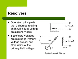
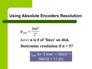
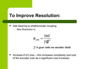
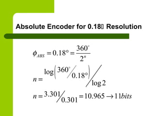
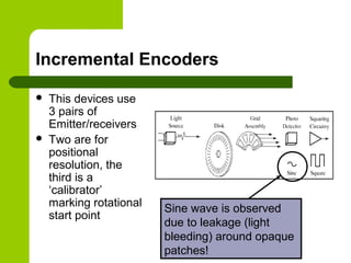
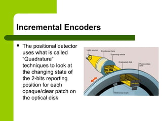
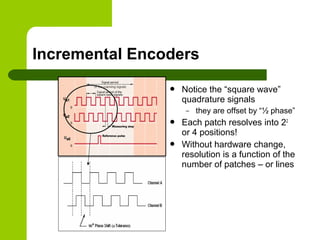
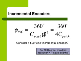
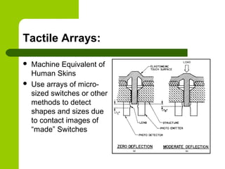
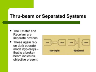
Sensing for Robotics and Control
ME 4135
R. R. Lindeke
General Ideas about Sensors
 Sensor are truly systems!
 Sensors systems consist of three separable
ideas:
 Informational sources: physically measurable data
sources (light beams, audio beams, electrical fields, etc)
 Detector areas: Devices that react to changes in the
informational sources
 Data Interpreters: devices (hard or soft based) that
convert informational changes into useful information
Sensor Topics
 Positional Control Sensing
– Kinesethic Sensing
 Resolvers
 Absolute Encoders
 Incremental Encoders
 Environmental Sensors
– Contact
 Point
 Field Sensors
– Proximity – typically single point
– Remote
 Single Point
 Field Sensors
Kinesethic Sensing
 These sensors provide feedback information
to the joint/link controllers (servo information)
 They use analog or digital informational
responses
 We will explore 3 generally used types:
– Resolvers
– Absolute Encoders
– Incremental Encoders
Resolvers
 Operating principle is
that a charged rotating
shaft will induce voltage
on stationary coils
 Secondary Voltages
are related to Primary
voltage as Sin and
Cos ratios of the
primary field voltage
Resolver Ideas:
Typically we use 2 stators
one (not shown) mounted
normal to an axis that is 90
away from the one thru
Winding A
Resolvers, cont.
 Position is determined for
computing stator ratio
 Winding A carries Sin
signal
 Winding B carries Cos
signal
 A/B = tan so
 Shaft position
=Atan2(B_Reading,
A_Reading)
 of interest
Resolver Issues
 These devices are susceptible to Electrical
Noise – must be highly shielded
 Usually use gearing to improve resolution
 Typically are expensive but very rugged for
use in harsh “shock motion” environments
Optical Encoder Positional Sensors
 Based on Photoelectric source/receiver pairs
 Looks for change of state as changing receiver
signal level (binary switching)
 Uses a carefully designed disk with clear and
opaque patches to control light falling on a fixed
sensor as disk rotates
 Can be made ‘absolute’ with several pairs of
emitters/receivers or Incremental with 2 ‘out of
phase’ photosensors
Optical Servo Measurement Systems
 Absolute Encoders
– Use Glass Disk marked for positional resolution
– Read digital words (0010111011) at receiver to
represent shaft position
– Commonly Available with up to 16 bits of
information (216
) to convert into positional
resolution
Operating Principle
Zdcvkpsdjfpsdjfgoipsdjf
g’oadgn’oiardfgnd’oikrjg
hdar’okgjnsldkfgknllkknr
esffzsdfsdfkjfksdf;kkjnflll
l
Absolute Encoders – optical disks
Absolute Encoder Variations – 8bit
Comparing Natural Binary to Gray
Code
 Natural Binary give actual position when read
– Actual position is known w/o analysis
 Gray code is designed so only one bit
changes “at a time”
– Where Bit change is subject to positional errors
as light “bleeds” around patch edges
 Gray codes are, therefore, less error prone,
but require an ‘intelligent converter’ to give
actual shaft position
Using Absolute Encoders Resolution:
360
2
: n is # of 'lines' on disk
Determine resolution if n = 5?
ABS n
here
φ
°
=
ABS for ‘5 liner’ = 360/25
=
360/32 = 11.25
To Improve Resolution:
 Add Gearing to shaft/encoder coupling
– New Resolution is:
 Increase # of Lines – this increases complexity and cost
of the encoder (can be a significant cost increase)
360
2
is gear ratio on encoder shaft
ABS n
φ
γ
γ
=
o
g
Absolute Encoder for 0.18 Resolution
( )
360
0.18
2
360log
0.18
log2
3.301 10.965 11
0.301
ABS n
n
n bits
φ = ° =
°=
= = →
o
o
Incremental Encoders
 This devices use
3 pairs of
Emitter/receivers
 Two are for
positional
resolution, the
third is a
‘calibrator’
marking rotational
start point
Sine wave is observed
due to leakage (light
bleeding) around opaque
patches!
Incremental Encoders
 The positional detector
uses what is called
“Quadrature”
techniques to look at
the changing state of
the 2-bits reporting
position for each
opaque/clear patch on
the optical disk
Incremental Encoders
 Notice the “square wave”
quadrature signals
– they are offset by “½ phase”
 Each patch resolves into 22
or 4 positions!
 Without hardware change,
resolution is a function of the
number of patches – or lines
Incremental Encoders
2
360 360
2 4
INC
patch patchC C
φ = =
o o
g
For 500 line Inc. encoders,
resolution = .18 (w/o gearing)
Consider a 500 ‘Line’ incremental encoder?
Comparing Absolute and Incremental
Encorders:
 Incremental are usually cheaper for same
level of resolution
 Absolute are able to provide positional
information at any time under power
– Incremental must be homed after power loss to
recalibrate count numbers
 Compared to resolvers, encoders are fragile
so must be shock protected during operation
Environmental Sensors
 These sensors provide ‘code decision making’ power
to the Manipulator
 These sensors can be simple
 Single point devices,
 Simple devices typically trigger yes/no decisions with switch
changes
 These sensors can be complex 2-D array (or even 3-
D field) devices
 Typically the receivers are complex arrays
 The data interpreters are sophisticated software and hardware
devices
 They can add “intelligence” for decision-making by the
manipulator
Contact Sensors – Force and
Deflection Sensing
 Force Sensors:
 Measure pressure
for gripping –
direct or indirect
 Measure
deflection during
contact – typical
of indirect contact
sensing
Contact Sensing
 Indirect contact sensors use Strain Gages (and
Hooke’s Law: Stress = E*Strain)
 The strain gage is a resistive device that exhibits a
change in resistance due to changes in shape
(length or width)
 The Strain Gage is mounted into a carefully built
(and calibrated) Wheatstone bridge
 small changes to the strain gages resistance, observed while
using a highly linear voltage source, are calibrated against
observed deflection
 This ‘bar’ deflection is strain and multiplying the strain times
the bar’s modulus of elasticity yields stress and hence applied
force!
 Stress = Force/Areabar
Contact Sensing
 Other contact sensor are “Direct
Reading”
 These devices use the piezoelectric
principle (effect) of the sensor material
 Piezoelectric effect states that in certain
material (quartz and some silicates)
applied forces (dynamically) will cause a
minute – but measurable – flow of
electrons along the surface of the crystal
based on di-polar disruption due to
shape change
 This flow is measure as a “Nano-current”
 The Current is linearized, amplified and
measured against a calibrated force
Contact Sensing
 A second general type would be the class of
“Micro-Switches”
 Like at the end of the Conveyor in the S100
cell
 Typically, applied forces directly move a
common contact between NC and NO contact
points
Examples of Micro-Switches:
 One Directional Reed
Switch:
 Omni-Directional Reed
Switch:
 Roller Contact Switch:
 Etc., etc., etc.!!!
Tactile Sensors – “feeler arrays”
 Potential Advantages of Tactile Sensors:
– They generate far fewer data bits (compared to
visual arrays) leading to simpler interpretation
analysis
– Collection is more readily controlled – we
completely control background and contrast
– The properties we measure are very close to
(exactly?!?) the properties we desire
Defining the “Ideal” Tactile Sensor
 They must be rugged and compliant to faults in the
manufacturing (operating) environment
 They should be “Smart” – That is able to process
most of the data into information for decision making
locally
– they send only results to the main controller
 Resolution should be on the order of about 100 mils
(about 10-4
inch)
 Sensors should respond to forces on the order of
about 5 -10 gmforce (0.1 N or 0.022 lbf)
Tactile Arrays:
 Machine Equivalent of
Human Skins
 Use arrays of micro-
sized switches or other
methods to detect
shapes and sizes due
to contact images of
“made” Switches
Tactile Arrays
 This device “measures”
shapes and sizes by
determining which of an
array of target points
have been charged
 Targets are “charged”
through contact with the
conductive Elastomer
skin and the PC ‘board’
targets
Tactile Arrays
 In this device, a series of thin
rods are pushed into an
object
 A “positive” image of the
object is produced by the
displaced rods
 In modern sensors,
displacement of each rod is
measured by the
detector/interpreter system –
this might be a vision system
located normal to the direction
of contact application or an
LVDT unit at each ‘rod’
Tactile Arrays
 The Anisotropic conductive
rubber sensor
 The ACR and gold contact
surface is separated when
unloaded
 As load is applied contact
patches grow indicating
shape and size of external
object and force being
applied
Proximity Sensors:
 Devices, including Photocells, Capacitance
sensors and Inductive sensors, that can be
used in areas that are near to but not
directly contacting an object to be sensed
 Like all sensors they use structured signal
sources, receive changes of state in their
energy (sensing) fields and interpret these
changes with signal changes to the “outside”
Photo Sensors
 The modern photosensor (in the
proximity range) emits
modulated light (at infrared or
near-infrared wavelengths). The
emitters are LED.
 The receivers (phototransistors)
are ‘tuned’ to be sensitive to the
wavelength of the source emitter
during the ‘on’ steps in the
modulated output stream
 The interpreters are (typically)
transistors that switch the power
(or ground) source on to the
output lead
Diffuse Mode Photosensor
 In proximity mode, the device is
looking for its own emitted beam
reflected back to its paired receiver
 The level of light falling on the
receiver to trigger positive response
can be ‘tuned’ to the task
 The sensors can be tuned to “Light-
Operate” or “Dark-Operate”
 Light operate means positive output
when reflective light is sensed
 Dark operate means positive output
when NO reflective light is sensed
Retro-Reflective Photosensors
 These devices rely on
“broken beams” to
detect
 They are “typically”
dark operate – that is
waiting for the object to
interrupt the light path
to the reflector
Thru-beam or Separated Systems
 The Emitter and
Receiver are
separate devices
 These again rely
on dark operate
mode (typically) –
that is a broken
beam indicates
objective present
Inductive Sensors
They typically oscillate
In ranges: 3 KHz – 1MHz
Inductive Sensors
Shielded types have slightly longer
range but smaller field of view
Uses:
 Inductive Sensors can (only) detect metals
as they draw power by induced surface
currents (eddy currents)
 The more magnetic the metal the greater the
sensor’s range
Principles of Capacitive Sensing
Uses And Capabilities
 Capacitive Sensors are able to detect any
material that raises the field dielectric in the
vicinity of the sensor
– In air this is nearly any other material!
Uses of Capacitive Sensors:
Typical Application of
Capacitive Sensor:
Detecting Liquid
(H2O) levels in bottles
When properly calibrated, the sensor can
detect any higher Dielectric Material thru
any lower Dielectric Material
Dielectric Values of
Various Materials:

Sensing for robotics and control s set13

  • 1.
    Sensing for Roboticsand Control ME 4135 R. R. Lindeke
  • 2.
    General Ideas aboutSensors  Sensor are truly systems!  Sensors systems consist of three separable ideas:  Informational sources: physically measurable data sources (light beams, audio beams, electrical fields, etc)  Detector areas: Devices that react to changes in the informational sources  Data Interpreters: devices (hard or soft based) that convert informational changes into useful information
  • 3.
    Sensor Topics  PositionalControl Sensing – Kinesethic Sensing  Resolvers  Absolute Encoders  Incremental Encoders  Environmental Sensors – Contact  Point  Field Sensors – Proximity – typically single point – Remote  Single Point  Field Sensors
  • 4.
    Kinesethic Sensing  Thesesensors provide feedback information to the joint/link controllers (servo information)  They use analog or digital informational responses  We will explore 3 generally used types: – Resolvers – Absolute Encoders – Incremental Encoders
  • 5.
    Resolvers  Operating principleis that a charged rotating shaft will induce voltage on stationary coils  Secondary Voltages are related to Primary voltage as Sin and Cos ratios of the primary field voltage
  • 6.
    Resolver Ideas: Typically weuse 2 stators one (not shown) mounted normal to an axis that is 90 away from the one thru Winding A
  • 7.
    Resolvers, cont.  Positionis determined for computing stator ratio  Winding A carries Sin signal  Winding B carries Cos signal  A/B = tan so  Shaft position =Atan2(B_Reading, A_Reading)  of interest
  • 8.
    Resolver Issues  Thesedevices are susceptible to Electrical Noise – must be highly shielded  Usually use gearing to improve resolution  Typically are expensive but very rugged for use in harsh “shock motion” environments
  • 9.
    Optical Encoder PositionalSensors  Based on Photoelectric source/receiver pairs  Looks for change of state as changing receiver signal level (binary switching)  Uses a carefully designed disk with clear and opaque patches to control light falling on a fixed sensor as disk rotates  Can be made ‘absolute’ with several pairs of emitters/receivers or Incremental with 2 ‘out of phase’ photosensors
  • 10.
    Optical Servo MeasurementSystems  Absolute Encoders – Use Glass Disk marked for positional resolution – Read digital words (0010111011) at receiver to represent shaft position – Commonly Available with up to 16 bits of information (216 ) to convert into positional resolution
  • 11.
  • 12.
    Absolute Encoders –optical disks
  • 13.
  • 14.
    Comparing Natural Binaryto Gray Code  Natural Binary give actual position when read – Actual position is known w/o analysis  Gray code is designed so only one bit changes “at a time” – Where Bit change is subject to positional errors as light “bleeds” around patch edges  Gray codes are, therefore, less error prone, but require an ‘intelligent converter’ to give actual shaft position
  • 15.
    Using Absolute EncodersResolution: 360 2 : n is # of 'lines' on disk Determine resolution if n = 5? ABS n here φ ° = ABS for ‘5 liner’ = 360/25 = 360/32 = 11.25
  • 16.
    To Improve Resolution: Add Gearing to shaft/encoder coupling – New Resolution is:  Increase # of Lines – this increases complexity and cost of the encoder (can be a significant cost increase) 360 2 is gear ratio on encoder shaft ABS n φ γ γ = o g
  • 17.
    Absolute Encoder for0.18 Resolution ( ) 360 0.18 2 360log 0.18 log2 3.301 10.965 11 0.301 ABS n n n bits φ = ° = °= = = → o o
  • 18.
    Incremental Encoders  Thisdevices use 3 pairs of Emitter/receivers  Two are for positional resolution, the third is a ‘calibrator’ marking rotational start point Sine wave is observed due to leakage (light bleeding) around opaque patches!
  • 19.
    Incremental Encoders  Thepositional detector uses what is called “Quadrature” techniques to look at the changing state of the 2-bits reporting position for each opaque/clear patch on the optical disk
  • 20.
    Incremental Encoders  Noticethe “square wave” quadrature signals – they are offset by “½ phase”  Each patch resolves into 22 or 4 positions!  Without hardware change, resolution is a function of the number of patches – or lines
  • 21.
    Incremental Encoders 2 360 360 24 INC patch patchC C φ = = o o g For 500 line Inc. encoders, resolution = .18 (w/o gearing) Consider a 500 ‘Line’ incremental encoder?
  • 22.
    Comparing Absolute andIncremental Encorders:  Incremental are usually cheaper for same level of resolution  Absolute are able to provide positional information at any time under power – Incremental must be homed after power loss to recalibrate count numbers  Compared to resolvers, encoders are fragile so must be shock protected during operation
  • 23.
    Environmental Sensors  Thesesensors provide ‘code decision making’ power to the Manipulator  These sensors can be simple  Single point devices,  Simple devices typically trigger yes/no decisions with switch changes  These sensors can be complex 2-D array (or even 3- D field) devices  Typically the receivers are complex arrays  The data interpreters are sophisticated software and hardware devices  They can add “intelligence” for decision-making by the manipulator
  • 24.
    Contact Sensors –Force and Deflection Sensing  Force Sensors:  Measure pressure for gripping – direct or indirect  Measure deflection during contact – typical of indirect contact sensing
  • 25.
    Contact Sensing  Indirectcontact sensors use Strain Gages (and Hooke’s Law: Stress = E*Strain)  The strain gage is a resistive device that exhibits a change in resistance due to changes in shape (length or width)  The Strain Gage is mounted into a carefully built (and calibrated) Wheatstone bridge  small changes to the strain gages resistance, observed while using a highly linear voltage source, are calibrated against observed deflection  This ‘bar’ deflection is strain and multiplying the strain times the bar’s modulus of elasticity yields stress and hence applied force!  Stress = Force/Areabar
  • 26.
    Contact Sensing  Othercontact sensor are “Direct Reading”  These devices use the piezoelectric principle (effect) of the sensor material  Piezoelectric effect states that in certain material (quartz and some silicates) applied forces (dynamically) will cause a minute – but measurable – flow of electrons along the surface of the crystal based on di-polar disruption due to shape change  This flow is measure as a “Nano-current”  The Current is linearized, amplified and measured against a calibrated force
  • 27.
    Contact Sensing  Asecond general type would be the class of “Micro-Switches”  Like at the end of the Conveyor in the S100 cell  Typically, applied forces directly move a common contact between NC and NO contact points
  • 28.
    Examples of Micro-Switches: One Directional Reed Switch:  Omni-Directional Reed Switch:  Roller Contact Switch:  Etc., etc., etc.!!!
  • 29.
    Tactile Sensors –“feeler arrays”  Potential Advantages of Tactile Sensors: – They generate far fewer data bits (compared to visual arrays) leading to simpler interpretation analysis – Collection is more readily controlled – we completely control background and contrast – The properties we measure are very close to (exactly?!?) the properties we desire
  • 30.
    Defining the “Ideal”Tactile Sensor  They must be rugged and compliant to faults in the manufacturing (operating) environment  They should be “Smart” – That is able to process most of the data into information for decision making locally – they send only results to the main controller  Resolution should be on the order of about 100 mils (about 10-4 inch)  Sensors should respond to forces on the order of about 5 -10 gmforce (0.1 N or 0.022 lbf)
  • 31.
    Tactile Arrays:  MachineEquivalent of Human Skins  Use arrays of micro- sized switches or other methods to detect shapes and sizes due to contact images of “made” Switches
  • 32.
    Tactile Arrays  Thisdevice “measures” shapes and sizes by determining which of an array of target points have been charged  Targets are “charged” through contact with the conductive Elastomer skin and the PC ‘board’ targets
  • 33.
    Tactile Arrays  Inthis device, a series of thin rods are pushed into an object  A “positive” image of the object is produced by the displaced rods  In modern sensors, displacement of each rod is measured by the detector/interpreter system – this might be a vision system located normal to the direction of contact application or an LVDT unit at each ‘rod’
  • 34.
    Tactile Arrays  TheAnisotropic conductive rubber sensor  The ACR and gold contact surface is separated when unloaded  As load is applied contact patches grow indicating shape and size of external object and force being applied
  • 35.
    Proximity Sensors:  Devices,including Photocells, Capacitance sensors and Inductive sensors, that can be used in areas that are near to but not directly contacting an object to be sensed  Like all sensors they use structured signal sources, receive changes of state in their energy (sensing) fields and interpret these changes with signal changes to the “outside”
  • 36.
    Photo Sensors  Themodern photosensor (in the proximity range) emits modulated light (at infrared or near-infrared wavelengths). The emitters are LED.  The receivers (phototransistors) are ‘tuned’ to be sensitive to the wavelength of the source emitter during the ‘on’ steps in the modulated output stream  The interpreters are (typically) transistors that switch the power (or ground) source on to the output lead
  • 37.
    Diffuse Mode Photosensor In proximity mode, the device is looking for its own emitted beam reflected back to its paired receiver  The level of light falling on the receiver to trigger positive response can be ‘tuned’ to the task  The sensors can be tuned to “Light- Operate” or “Dark-Operate”  Light operate means positive output when reflective light is sensed  Dark operate means positive output when NO reflective light is sensed
  • 38.
    Retro-Reflective Photosensors  Thesedevices rely on “broken beams” to detect  They are “typically” dark operate – that is waiting for the object to interrupt the light path to the reflector
  • 39.
    Thru-beam or SeparatedSystems  The Emitter and Receiver are separate devices  These again rely on dark operate mode (typically) – that is a broken beam indicates objective present
  • 40.
    Inductive Sensors They typicallyoscillate In ranges: 3 KHz – 1MHz
  • 41.
    Inductive Sensors Shielded typeshave slightly longer range but smaller field of view
  • 42.
    Uses:  Inductive Sensorscan (only) detect metals as they draw power by induced surface currents (eddy currents)  The more magnetic the metal the greater the sensor’s range
  • 43.
  • 44.
    Uses And Capabilities Capacitive Sensors are able to detect any material that raises the field dielectric in the vicinity of the sensor – In air this is nearly any other material!
  • 45.
    Uses of CapacitiveSensors: Typical Application of Capacitive Sensor: Detecting Liquid (H2O) levels in bottles When properly calibrated, the sensor can detect any higher Dielectric Material thru any lower Dielectric Material
  • 46.