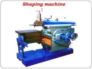
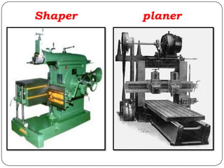
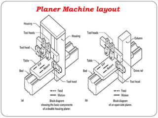
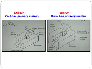
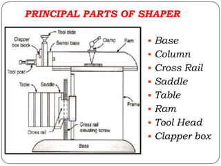
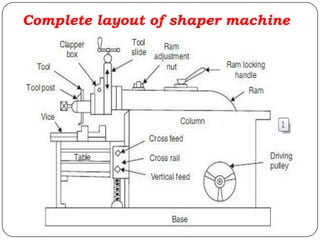
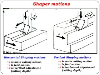
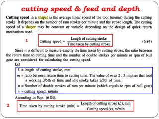
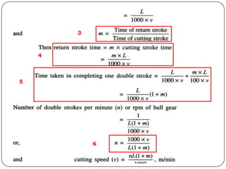
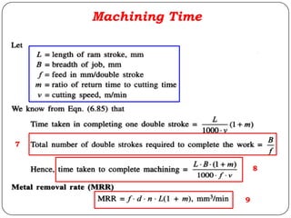
High Profile Call Girls Nagpur Isha Call 7001035870 Meet With Nagpur Escorts
Lecture 6 shaping and planing
1. Faculty of Engineering
Mechanical Engineering Department
Lecture No. (6)
معدات و أساليبتشغيل(1)
Machining Techniques & Equipments (1)
Dr. Rania Mostafa
Shaping & Planing processes
2. Outline
Introduction
Operations on shaping machine
Advantages of shaper
Shaper limitations
Principal parts of shaper
Principal of working
Quick return mechanism
Specifications of shaping machine
Feed drive mechanism
Shaper tool materials, shape and size
Shaper cutting tool terminologies
Cutting motions
Cutting speed, feed and depth of cut
Machining time calculations
4. INTRODUCTION
Shaper is defined as a process for removing metal
surfaces in horizontal, vertical and angular planes by
the use of a single point cutting tool held on the ram
that reciprocates the tool.
Machine Features:
Single point cutting tool is used for machining. Tool is
clamped in the tool post mounted on the ram of the
machine.
The ram reciprocates to and for, tool cuts the material in
the forward stroke, No cutting during return (back) stroke.
Job is held rigidly in a vise.
5. The Shaper is a machine tool used
primarily for:
Producing a flat or plane surface which
may be in a horizontal, a vertical or an
angular plane.
Making slots, grooves and keyways.
Producing contour of concave/convex or
a combination of these.
Operations on Shaper
10. Advantages Of Shapers
The single point cutting tools used in shapers
are inexpensive, these tools can be easily
grounded to any desirable shape.
The simplicity and ease of holding work, its
easy adjustment, and the simple tool give the
shaper its great flexibility.
Shaper set up is very quick and easy and can
be readily changed from one job to another.
Thin or fragile jobs can be conveniently
machined on shapers because of lower cutting
forces.
11. The shaper is unsuitable for generating flat
surfaces on very large parts because of the
limitations on the stroke and overhang the ram
Planer solved this problem by applying the
linear primary motion to the work-piece and
feeding the tool at right angles to this motion.
The primary motion is accomplished by a rack
and pinion drive using a variable speed motor.
Shaper limitations
18. PARTS OF SHAPER
BASE
It made of cast iron to resist vibration and take up
high compressive load.
It Provides support for other parts of machine.
COLUMN
The column is a box like casting mounted vertically on
top of base.
It has Two guide ways. One vertical guide-way in the
front over which a cross slide moves up and down.
Second horizontal guide ways on top over which ram
reciprocate.
The reciprocating mechanism is housed inside the
column
19. CROSS RAIL
It is on the front vertical guide ways of the column.
The table may be raised or lowered to accommodate
different sizes of jobs by rotating an elevating screw
which causes the cross rail to slide up and down
on the vertical face of the column.
Saddle
The saddle is mounted on the cross rail which holds
the table firmly on its top.
Crosswise movement of the saddle by rotating the
cross feed screw by hand or power causes the table to
move sideways.
PARTS OF SHAPER
20. TABLE
It mounted on a saddle which is located above
the cross rail. Top and sides are accurately
machined and have T slots.
RAM
It supports tool head on its front. It reciprocates
on accurately horizontal machined guide ways
on top of column
TOOL HEAD
It fitted on the face of ram. Holds the tool rigidly.
Provide vertical and angular depth for the tool
Tool head can be positioned at any angle
PARTS OF SHAPER
21. Clapper Box
The clapper box houses the clapper block which is
connected to it by means of hinge pin.
The tool post is mounted upon the clapper block to
prevent interference between the tools and work-piece
on the return stroke
On the forward cutting stroke the clapper block fits
securely to the clapper box to make a rigid tool on the
work.
It prevents the tool cutting edge form dragging and
wear.
The work surface is also prevented from any damage
due to dragging.
PARTS OF SHAPER
24. Principal of working
The job is rigidly fixed on the machine table.
The single point cutting tool held properly in the tool post is
mounted on a reciprocating ram.
The reciprocating motion of the ram is obtained by a quick
return motion mechanism.
As the ram reciprocates, the tool cuts the material during
its forward stroke. During return, there is no cutting action
and this stroke is called the idle stroke.
The forward and return strokes constitute one operating
cycle of the shaper.
In order to reduce the time wasted during the return non-
cutting stroke, shaping machines are fitted with a quick-
return mechanism, usually of the crank and slotted-link
design.
25. Traversing head shaper
Double stroke= cutting stroke + return stroke
Stroke starts slightly before the work piece (A) and ends after the work piece (B)
Total stroke length = A + L+ B
27. Working Of Quick Return Mechanism
The crank AB (of adjustable length R) rotates with a
uniform angular speed. The crank pin B is in the
shape of a die block which is free to slide inside the
slot in the slotted lever OBC. This slotted lever is
pivoted at O and the other end C is connected to the
ram by a short link arm as shown in Fig. a. When the
crank AB rotates clockwise from position AB1to AB2,
the ram moves forward from left to right and when it
rotates from position AB2 to AB1the ram returns back
to its original position. Clearly the time taken to
complete forward stroke is proportional to angle α(refer
to Fig. b) and the return stroke is completed in less
time which is proportional to angle β.
30. Feed drive mechanism
The amount of feed can be adjusted by
shifting the bolt (b).
During roughing operation the pawl shifts the
ratchet wheel by several teeth and during
finishing operation it moves tooth by tooth
Example of feed calculation:
If the screw spindle of the table has a pitch of 4mm,
it turns once and the ratchet wheel has 20 teeth,
what distance will the table move while the ratchet
rotates by one tooth.
Answer = 0.2 mm
31. Specifications of Shaping Machine
Maximum length of Stroke of Ram
Power input
Floor Space required
Weight of the Machine
Cutting to Return Stroke ratio range
Feed range
Adjustment range (depth)
32. Cutting Tool Materials, Shapes & Sizes
Most shaper cutting tools are made from high
speed steel (HSS).
For cutting very hard materials, tungsten carbide
tools are used.
Shaper cutting tools are ground for cutting
horizontally right or left, vertically right or left, and
for grooving.
Cutting tool shape varies with the material to be
machined and the type of cut required.
36. Shaper motions
• a is main cutting motion
• c is feed motion
• d is Vertical adjustment
(cutting depth)
Horizontal Shaping motions Vertical Shaping motions
• a is main cutting motion
• c is feed motion
• d is horizontal adjustment
(cutting depth)