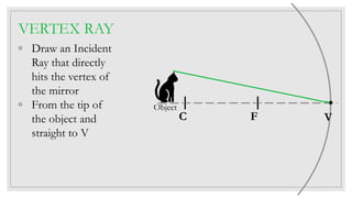
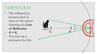
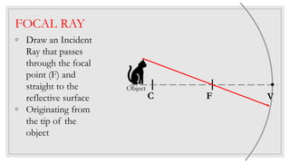
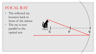
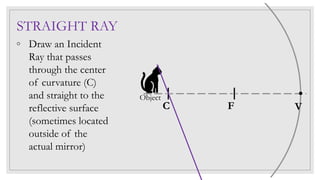
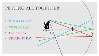
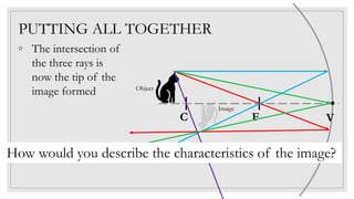
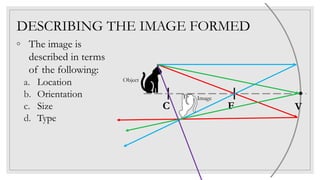
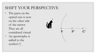
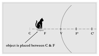
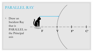
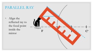
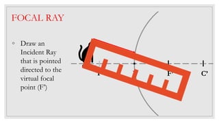
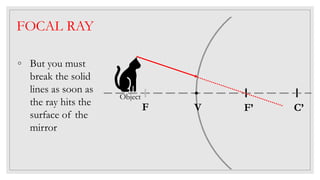
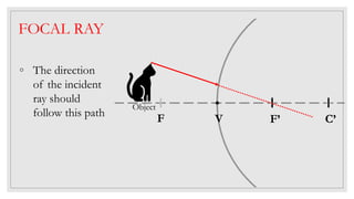
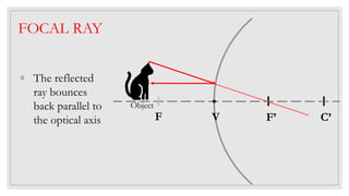
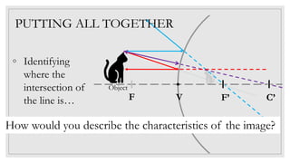
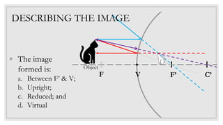
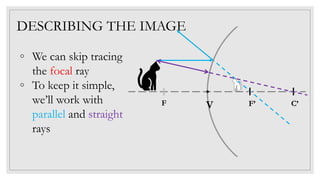
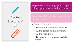
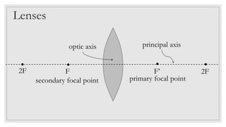
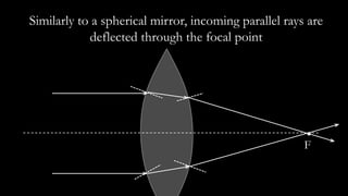
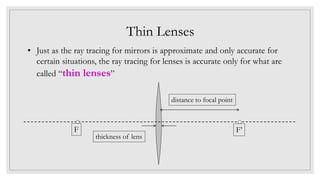
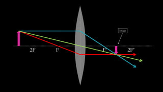
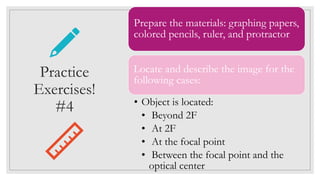
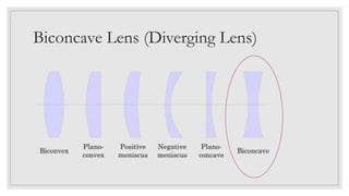
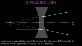
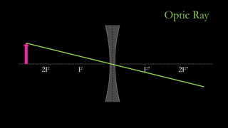
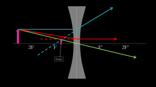
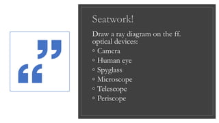
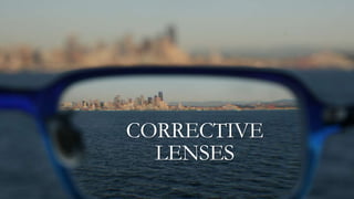
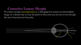
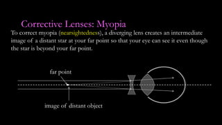
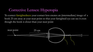
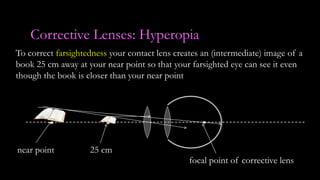
IMAGE
FORMATION
ON A
CONCAVE
MIRROR
Ray Diagram
◦ a diagram that traces the path that light takes in
order for a person to view a point on the image of
an object
◦ a technique used to determine the characteristics of
the image formed by light on or by different
surfaces.
Tips on
Ray
Diagram:
We assume light to
travel along straight
paths, like the path of a
particle as it travels
along a medium.
Tips on
Ray
Diagram:
As soon as light hits the
REFLECTING surface
of the mirror, it will,
obviously, start to
BOUNCE BACK.
Tips on
Ray
Diagram:
The names of the major
rays used describe the
orientation of the
INCIDENT RAY.
Parts of the ray diagram
◦ Notice that the
shape is a circle and
the diameter is what
is called the “optical
axis”
◦ Ensure that your
circle has a perfect
shape
r
Parts of the ray diagram
◦ We shall be using
only this part of the
circle ALWAYS
◦ C is called center of
curvature
◦ F is called the focal
point
◦ B is called vertex
C F V
r
focal length
HOW DOES A SPHERICAL CONCAVE
MIRROR LOOK LIKE?
Reflecting part is the
INNER layer.
A concave mirror’s
reflecting surface is on
the ‘caved’ or ‘shrunken’
part of the mirror.
C F V
Object
object is placed beyond C
PARALLEL RAY
◦ Draw an Incident
Ray that is
PARALLEL to the
Principal axis
◦ From the tip of
the object and
straight to the
reflective surface
C F V
Object
PARALLEL RAY
◦ The reflected ray
will bounce back in
front of the
mirror, passing
through the focal
point, F
◦ You may extend
the line a little bit
C F V
Object
VERTEX RAY
◦ Draw an Incident
Ray that directly
hits the vertex of
the mirror
◦ From the tip of
the object and
straight to V
C F V
Object
VERTEX RAY
◦ The reflected ray
bounces back in
front of the mirror
following the Law
of Reflection
◦ θi = θr
◦ You may use a
protractor for this
C F V
Object
θi
θr
FOCAL RAY
◦ Draw an Incident
Ray that passes
through the focal
point (F) and
straight to the
reflective surface
◦ Originating from
the tip of the
object
C F V
Object
FOCAL RAY
◦ The reflected ray
bounces back in
front of the mirror
◦ The ray is now
parallel to the
optical axis C F V
Object
STRAIGHT RAY
◦ Draw an Incident
Ray that passes
through the center
of curvature (C)
and straight to the
reflective surface
(sometimes located
outside of the
actual mirror)
C F V
Object
PUTTING ALL TOGETHER
◦ PARALLEL RAY
C F V
Object
◦ VERTEX RAY
◦ FOCAL RAY
◦ STRAIGHT RAY
PUTTING ALL TOGETHER
C F V
Object
◦ The intersection of
the three rays is
now the tip of the
image formed
Image
How would you describe the characteristics of the image?
DESCRIBING THE IMAGE FORMED
C F V
Object
◦ The image is
described in terms
of the following:
a. Location
b. Orientation
c. Size
d. Type
Image
Location
(the location of the image relative to the mirror)
 Between F and V
 At F
 Between F and C
 At C
 Beyond C
Location
(the location of the image relative to the mirror)
 Location is also accurately measured if the ray
diagram used an appropriate scale
 Exact measurements using a ruler or a protractor
was used and the diagram was done on a graphing
paper
Orientation
(position of the object)
 Upright – if the image is mounted just like the
object (formed above the optical axis)
 Inverted – if the image is mounted in the opposite
direction as the object (formed below the optical
axis)
Size
(relates the size of the image compared to the object)
 Reduced – if the image looks smaller than the
object
 Enlarged/ Magnified – if the image is bigger than
the object
Type
(based on the kind of reflected rays from which the
image was formed)
 Real – if the image is formed in front of the
mirror (real rays or solid lines were used)
 Virtual– if the image is formed behind/inside the
mirror (virtual rays or broken lines were used)
◦ Therefore, when an
object is placed beyond
the center of curvature
of a concave mirror…
◦ The image formed is:
a. Between C & F;
b. Inverted;
c. Reduced; and
d. Real
C F V
◦ For your outputs, we
can skip tracing the
focal and straight rays
◦ We can rely on parallel
and vertex rays for
accuracy and simplicity
C F V
Take Note!
◦ We will ALL use a focal
length that is around 2
to 4 cm
◦ f = r / 2
◦ Focal length is half of a
radius
r
Take Note!
◦ Cut out a piece of
cardboard into a circle
using this length
◦ Poke a hole at the center
to mark your center of
curvature
◦ Use this as your tracer
curved mirrors
r
f
Practice
Exercises!
#2
Prepare the materials: graphing papers,
colored pencils, ruler, and protractor
Locate and describe the image for the
following cases:
• Object is located:
• At the center of the curvature
• Between the center of curvature
and the focal point
• At the focal point
• Between the focal point and the
vertex
IMAGE
FORMATION
ON A
CONVEX
MIRROR
HOW DOES A SPHERICAL CONVEX
MIRROR LOOK LIKE?
Reflecting part is the
OUTER layer.
A convex mirror’s reflecting surface
is on the “bulging” part of the mirror.
◦ The parts on the
optical axis is now
on the other side
of the mirror
They are all
considered virtual
◦ An apostrophe is
added to the
symbol (‘)
C’F’V
!
SHIFT YOUR PERSPECTIVE
C’F’V
Object
FC
object is placed between C & F
C’F’V
Object
PARALLEL RAY
◦ Draw an
Incident Ray
that is
PARALLEL to
the Principal
axis
F
C’F’V
Object
PARALLEL RAY
◦ Align the
reflected ray to
the focal point
inside the
mirror
F
F C’F’V
Object
FOCAL RAY
◦ Draw an
Incident Ray
that is pointed
directed to the
virtual focal
point (F’)
C’F’V
Object
FOCAL RAY
◦ But you must
break the solid
lines as soon as
the ray hits the
surface of the
mirror
F
C’F’V
Object
FOCAL RAY
◦ The direction
of the incident
ray should
follow this path F
C’F’V
Object
FOCAL RAY
◦ The reflected
ray bounces
back parallel to
the optical axis F
C’F’V
Object
FOCAL RAY
◦ Extend the
reflected ray
towards the
inside of the
mirror
◦ Use a different
broken line
pattern
F
F C’F’V
Object
STRAIGHT RAY
◦ Draw an
Incident Ray
that is pointed
directly to the
virtual center
of curvature,
(C’)
C’F’V
Object
STRAIGHT RAY
◦ The incident
ray is also the
reflected ray so
the arrow has
two (2) arrow
heads
F
PUTTING ALL TOGETHER
◦ PARALLEL RAY
◦ FOCAL RAY
◦ STRAIGHT RAY
C’F’V
Object
F
PUTTING ALL TOGETHER
C’F’V
Object
How would you describe the characteristics of the image?
◦ Identifying
where the
intersection of
the line is… F
C’F’V
Object
DESCRIBING THE IMAGE
◦ The image
formed is:
a. Between F’ & V;
b. Upright;
c. Reduced; and
d. Virtual
F
DESCRIBING THE IMAGE
C’F’VF
◦ We can skip tracing
the focal ray
◦ To keep it simple,
we’ll work with
parallel and straight
rays
Prepare the materials: graphing papers,
colored pencils, ruler, and protractor
Locate and describe the image for the
following cases:
• Object is located:
• Beyond the center of curvature
• At the center of the curvature
• At the focal point
• Between the focal point and the
vertex
Practice
Exercises!
#3
Lesson Review!
Answer on your notebook the
questions on Page 105
FOLDABLES!
Prepare a paper half the size
of short bond paper.
Please refer to the instructions
on Page 102.
How can you demonstrate the law of
reflection?
When light strikes a mirror, the angle of reflection equals the angle of incidence. You can
demonstrate the law of reflection by measuring the angles of incident and reflected light rays
between an object and a mirror
Go to page 106 and find a partner
Reserve/prepare ALL the materials
Follow the steps in the procedure
Write your outputs on a short bond paper
30 minutes only!
REFRACTION AND
LENSES
LESSON 2
ESSENTIAL QUESTION
What happens to light as it moves from one
transparent substance to another?
ESSENTIAL QUESTION
How do convex lenses and concave lenses
affect light?
ESSENTIAL QUESTION
How doe eyes detect light and color?
INQUIRY
Name some
objects that
enable you
to see small
things.
(See page
107)
WHAT HAPPENS TO LIGHT THAT
PASES FROM ONE TRANSPARENT
SUBSTANCE TO ANOTHER?
Tasks: (Go to page 108)
◦ Prepare the materials
◦ Follow the steps in the procedure
◦ Answer the “Think About This” in a Size
2 CW paper (per lab group)
◦ 15 minutes only!
Launch Lab
(1)
The diagram for the first setup
should show light traveling from the
air/water/oil to glass (test tube) to
water/oil to glass/beaker to air.
POST-LAB DISCUSSION
airglasswaterglassoil
The light seemed to
be bent
(2)
The test tube with oil was not visible
when it was immersed in oil, but it
was visible when it was immersed in
water. The test tubes with air and
water were always visible.
POST-LAB DISCUSSION
(2)
The test tube with oil was not visible
when it was immersed in oil, but it
was visible when it was immersed in
water. The test tubes with air and
water were always visible.
POST-LAB DISCUSSION
(2)
The test tube with oil was not visible
when it was immersed in oil, but it
was visible when it was immersed in
water. The test tubes with air and
water were always visible.
POST-LAB DISCUSSION
WHAT DOES REFRACTION REFER TO?
Bending of light as it passes from one
medium to another
If the light moves into a
transparent substance with a
different index of refraction
at 90° to the surface, it
changes speed, but it does
not change direction
If it enters at an angle other
than 90°, it changes speed
and changes direction.
This is also known as
refraction.
Index of refraction
◦ The index of refraction for a material is the ratio of the
velocity of light, c, in a vacuum (3 x 10⁸ m/s) to the
velocity, v, through the material.
𝑛 =
𝑐
𝑣
Based on Table 1, which of the
following media will make the
light wave bend the most?
◦ Ice
◦ Water
◦ Glass
◦ Diamond
Which way will light move as it
enters a medium that causes it
to move more slowly?
Towards the Normal line
Describe a situation in
which a light ray
would move away
from the normal line
while passing from
one medium to
another.
IMAGE
FORMATION
THROUGH
LENSES
Biconvex Lens (Converging Lens)
Convex Glass Surface
C
axis
A convex surface is called “converging” because parallel rays converge towards one
another
AIR (fast) GLASS (slow)
normal line
fast to slow bends towards
the normal
Convex Glass Surface
Caxis
The surface is converging for both air to glass rays and glass to air rays
AIRGLASS
normal line
slow to fast bends away
from the normal
Caxis
A concave surface is called “diverging” because parallel rays diverge away from one
another
Concave Glass Surface
AIR GLASS
C axis
Again, the surface is diverging for both air to glass rays and glass to air rays
Concave Glass Surface
AIRGLASS
Converging Lens
◦The focal point of a curved
mirror was the image point of a
distant star
◦ It is the same for a lens.
◦ The focal point of a converging lens
is where the incoming rays from a
distant star all intersect.
◦A distant star is used to guarantee
that the incoming rays are parallel
Focal point
Focal distance
F’F
Lenses
optic axis
2F 2F
principal axis
secondary focal point primary focal point
F
Similarly to a spherical mirror, incoming parallel rays are
deflected through the focal point
Thin Lenses
• Just as the ray tracing for mirrors is approximate and only accurate for
certain situations, the ray tracing for lenses is accurate only for what are
called “thin lenses”
F’F
thickness of lens
distance to focal point
How is the image formed by a converging
lens?
Converging Lens: Ray Tracing Rules
Rule 1:
Similarly to a spherical mirror, incoming parallel rays are deflected through the
focal point.
FF
Converging Lens: Ray Tracing Rules
Rule 2:
Rays passing through the center of the lens are undeflected, they continue straight
through without being bent. Several rays are shown here as examples.
FF
Converging Lens: Ray Tracing Rules
Rule 3:
The reverse of Rule 1, rays passing through the focal point are deflected to exit
parallel to the axis
FF
Major Rays used in Ray Tracing
The incident light ray from the object that is
parallel to the principal axis will be refracted
passing through the principal focal point after
passing through the optic axis.
Parallel Ray
F F’2F 2F’
Parallel Ray
The incident light ray that passes through the
secondary focal point will be refracted parallel
to the principal axis.
Focal Ray
F F’2F 2F’
Focal Ray
The incident light ray that seems to pass
through the optical center will not be refracted.
Optic Ray
F F’2F 2F’
Optic Ray
F F’2F 2F’
Image
Prepare the materials: graphing papers,
colored pencils, ruler, and protractor
Locate and describe the image for the
following cases:
• Object is located:
• Beyond 2F
• At 2F
• At the focal point
• Between the focal point and the
optical center
Practice
Exercises!
#4
Biconcave Lens (Diverging Lens)
F’F
In diverging lens, parallel rays are deflected such that when extended backwards, they
appear to be coming from the focal point on the other side.
DIVERGING LENS
Diverging Lens: Ray Tracing
F’F
Parallel rays are deflected so they appear to be coming from the focal point in front
of the lens.
Diverging Lens: Ray Tracing
F’F
Just like for converging lenses, rays that pass through the center of the lens
continue undeflected (straight) through the lens.
Diverging Lens: Ray Tracing
F’F
Rays that, if extended, would pass through the focal point on the other side of the
lens, are deflected to be parallel to the axis.
Major Rays used in Ray Tracing
The incident light ray from the object that is
parallel to the principal axis will be refracted as
if it came from the secondary focal point.
Parallel Ray
F F’2F 2F’
Parallel Ray
The incident light ray that seems to pass
through the principal focal point will be
refracted parallel to the principal axis.
Focal Ray
F F’2F 2F’
Focal Ray
The incident light ray that seems to pass
through the optical center will not be refracted.
Optic Ray
F F’2F 2F’
Optic Ray
F F’2F 2F’
Image
Prepare the materials: graphing papers,
colored pencils, ruler, and protractor
Locate and describe the image for the
following cases:
• Object is located:
• Beyond 2F
• At 2F
• At the focal point
• Between the focal point and the
optical center
Practice
Exercises!
#5
OPTICAL
DEVICES
wikipedia.org
Microscope
etsy.com
Spyglass
bebusinessed.com
Telescope
wikipedia.org
Camera
bhphotovideo.com
Camera
evolutionnews.com
Human
eye
Seatwork!
Draw a ray diagram on the ff.
optical devices:
◦ Camera
◦ Human eye
◦ Spyglass
◦ Microscope
◦ Telescope
◦ Periscope
CORRECTIVE
LENSES
Corrective Lenses: Myopia
To correct myopia (nearsightedness), a diverging lens creates an intermediate
image of a distant star at your far point so that your eye can see it even though
the star is beyond your far point.
Corrective Lenses: Myopia
To correct myopia (nearsightedness), a diverging lens creates an intermediate
image of a distant star at your far point so that your eye can see it even though
the star is beyond your far point.
far point
image of distant object
Corrective Lenses: Hyperopia
To correct farsightedness your contact lens creates an (intermediate) image of a
book 25 cm away at your near point so that your farsighted eye can see it even
though the book is closer than your near point
25 cmnear point
Corrective Lenses: Hyperopia
To correct farsightedness your contact lens creates an (intermediate) image of a
book 25 cm away at your near point so that your farsighted eye can see it even
though the book is closer than your near point
near point 25 cm
focal point of corrective lens

Ray Tracing

  • 1.
  • 2.
    Ray Diagram ◦ adiagram that traces the path that light takes in order for a person to view a point on the image of an object ◦ a technique used to determine the characteristics of the image formed by light on or by different surfaces.
  • 3.
    Tips on Ray Diagram: We assumelight to travel along straight paths, like the path of a particle as it travels along a medium.
  • 4.
    Tips on Ray Diagram: As soonas light hits the REFLECTING surface of the mirror, it will, obviously, start to BOUNCE BACK.
  • 5.
    Tips on Ray Diagram: The namesof the major rays used describe the orientation of the INCIDENT RAY.
  • 6.
    Parts of theray diagram ◦ Notice that the shape is a circle and the diameter is what is called the “optical axis” ◦ Ensure that your circle has a perfect shape r
  • 7.
    Parts of theray diagram ◦ We shall be using only this part of the circle ALWAYS ◦ C is called center of curvature ◦ F is called the focal point ◦ B is called vertex C F V r focal length
  • 8.
    HOW DOES ASPHERICAL CONCAVE MIRROR LOOK LIKE? Reflecting part is the INNER layer.
  • 9.
    A concave mirror’s reflectingsurface is on the ‘caved’ or ‘shrunken’ part of the mirror.
  • 10.
    C F V Object objectis placed beyond C
  • 11.
    PARALLEL RAY ◦ Drawan Incident Ray that is PARALLEL to the Principal axis ◦ From the tip of the object and straight to the reflective surface C F V Object
  • 12.
    PARALLEL RAY ◦ Thereflected ray will bounce back in front of the mirror, passing through the focal point, F ◦ You may extend the line a little bit C F V Object
  • 13.
    VERTEX RAY ◦ Drawan Incident Ray that directly hits the vertex of the mirror ◦ From the tip of the object and straight to V C F V Object
  • 14.
    VERTEX RAY ◦ Thereflected ray bounces back in front of the mirror following the Law of Reflection ◦ θi = θr ◦ You may use a protractor for this C F V Object θi θr
  • 15.
    FOCAL RAY ◦ Drawan Incident Ray that passes through the focal point (F) and straight to the reflective surface ◦ Originating from the tip of the object C F V Object
  • 16.
    FOCAL RAY ◦ Thereflected ray bounces back in front of the mirror ◦ The ray is now parallel to the optical axis C F V Object
  • 17.
    STRAIGHT RAY ◦ Drawan Incident Ray that passes through the center of curvature (C) and straight to the reflective surface (sometimes located outside of the actual mirror) C F V Object
  • 18.
    PUTTING ALL TOGETHER ◦PARALLEL RAY C F V Object ◦ VERTEX RAY ◦ FOCAL RAY ◦ STRAIGHT RAY
  • 19.
    PUTTING ALL TOGETHER CF V Object ◦ The intersection of the three rays is now the tip of the image formed Image How would you describe the characteristics of the image?
  • 20.
    DESCRIBING THE IMAGEFORMED C F V Object ◦ The image is described in terms of the following: a. Location b. Orientation c. Size d. Type Image
  • 21.
    Location (the location ofthe image relative to the mirror)  Between F and V  At F  Between F and C  At C  Beyond C
  • 22.
    Location (the location ofthe image relative to the mirror)  Location is also accurately measured if the ray diagram used an appropriate scale  Exact measurements using a ruler or a protractor was used and the diagram was done on a graphing paper
  • 23.
    Orientation (position of theobject)  Upright – if the image is mounted just like the object (formed above the optical axis)  Inverted – if the image is mounted in the opposite direction as the object (formed below the optical axis)
  • 24.
    Size (relates the sizeof the image compared to the object)  Reduced – if the image looks smaller than the object  Enlarged/ Magnified – if the image is bigger than the object
  • 25.
    Type (based on thekind of reflected rays from which the image was formed)  Real – if the image is formed in front of the mirror (real rays or solid lines were used)  Virtual– if the image is formed behind/inside the mirror (virtual rays or broken lines were used)
  • 26.
    ◦ Therefore, whenan object is placed beyond the center of curvature of a concave mirror… ◦ The image formed is: a. Between C & F; b. Inverted; c. Reduced; and d. Real C F V
  • 27.
    ◦ For youroutputs, we can skip tracing the focal and straight rays ◦ We can rely on parallel and vertex rays for accuracy and simplicity C F V
  • 28.
    Take Note! ◦ Wewill ALL use a focal length that is around 2 to 4 cm ◦ f = r / 2 ◦ Focal length is half of a radius r
  • 29.
    Take Note! ◦ Cutout a piece of cardboard into a circle using this length ◦ Poke a hole at the center to mark your center of curvature ◦ Use this as your tracer curved mirrors r f
  • 30.
    Practice Exercises! #2 Prepare the materials:graphing papers, colored pencils, ruler, and protractor Locate and describe the image for the following cases: • Object is located: • At the center of the curvature • Between the center of curvature and the focal point • At the focal point • Between the focal point and the vertex
  • 31.
  • 32.
    HOW DOES ASPHERICAL CONVEX MIRROR LOOK LIKE? Reflecting part is the OUTER layer.
  • 33.
    A convex mirror’sreflecting surface is on the “bulging” part of the mirror.
  • 34.
    ◦ The partson the optical axis is now on the other side of the mirror They are all considered virtual ◦ An apostrophe is added to the symbol (‘) C’F’V ! SHIFT YOUR PERSPECTIVE
  • 35.
  • 36.
    C’F’V Object PARALLEL RAY ◦ Drawan Incident Ray that is PARALLEL to the Principal axis F
  • 37.
    C’F’V Object PARALLEL RAY ◦ Alignthe reflected ray to the focal point inside the mirror F
  • 38.
    F C’F’V Object FOCAL RAY ◦Draw an Incident Ray that is pointed directed to the virtual focal point (F’)
  • 39.
    C’F’V Object FOCAL RAY ◦ Butyou must break the solid lines as soon as the ray hits the surface of the mirror F
  • 40.
    C’F’V Object FOCAL RAY ◦ Thedirection of the incident ray should follow this path F
  • 41.
    C’F’V Object FOCAL RAY ◦ Thereflected ray bounces back parallel to the optical axis F
  • 42.
    C’F’V Object FOCAL RAY ◦ Extendthe reflected ray towards the inside of the mirror ◦ Use a different broken line pattern F
  • 43.
    F C’F’V Object STRAIGHT RAY ◦Draw an Incident Ray that is pointed directly to the virtual center of curvature, (C’)
  • 44.
    C’F’V Object STRAIGHT RAY ◦ Theincident ray is also the reflected ray so the arrow has two (2) arrow heads F
  • 45.
    PUTTING ALL TOGETHER ◦PARALLEL RAY ◦ FOCAL RAY ◦ STRAIGHT RAY C’F’V Object F
  • 46.
    PUTTING ALL TOGETHER C’F’V Object Howwould you describe the characteristics of the image? ◦ Identifying where the intersection of the line is… F
  • 47.
    C’F’V Object DESCRIBING THE IMAGE ◦The image formed is: a. Between F’ & V; b. Upright; c. Reduced; and d. Virtual F
  • 48.
    DESCRIBING THE IMAGE C’F’VF ◦We can skip tracing the focal ray ◦ To keep it simple, we’ll work with parallel and straight rays
  • 49.
    Prepare the materials:graphing papers, colored pencils, ruler, and protractor Locate and describe the image for the following cases: • Object is located: • Beyond the center of curvature • At the center of the curvature • At the focal point • Between the focal point and the vertex Practice Exercises! #3
  • 50.
    Lesson Review! Answer onyour notebook the questions on Page 105
  • 51.
    FOLDABLES! Prepare a paperhalf the size of short bond paper. Please refer to the instructions on Page 102.
  • 52.
    How can youdemonstrate the law of reflection? When light strikes a mirror, the angle of reflection equals the angle of incidence. You can demonstrate the law of reflection by measuring the angles of incident and reflected light rays between an object and a mirror Go to page 106 and find a partner Reserve/prepare ALL the materials Follow the steps in the procedure Write your outputs on a short bond paper 30 minutes only!
  • 53.
  • 54.
    ESSENTIAL QUESTION What happensto light as it moves from one transparent substance to another?
  • 55.
    ESSENTIAL QUESTION How doconvex lenses and concave lenses affect light?
  • 56.
    ESSENTIAL QUESTION How doeeyes detect light and color?
  • 57.
    INQUIRY Name some objects that enableyou to see small things. (See page 107)
  • 58.
    WHAT HAPPENS TOLIGHT THAT PASES FROM ONE TRANSPARENT SUBSTANCE TO ANOTHER? Tasks: (Go to page 108) ◦ Prepare the materials ◦ Follow the steps in the procedure ◦ Answer the “Think About This” in a Size 2 CW paper (per lab group) ◦ 15 minutes only! Launch Lab
  • 59.
    (1) The diagram forthe first setup should show light traveling from the air/water/oil to glass (test tube) to water/oil to glass/beaker to air. POST-LAB DISCUSSION
  • 60.
  • 61.
    (2) The test tubewith oil was not visible when it was immersed in oil, but it was visible when it was immersed in water. The test tubes with air and water were always visible. POST-LAB DISCUSSION
  • 62.
    (2) The test tubewith oil was not visible when it was immersed in oil, but it was visible when it was immersed in water. The test tubes with air and water were always visible. POST-LAB DISCUSSION
  • 63.
    (2) The test tubewith oil was not visible when it was immersed in oil, but it was visible when it was immersed in water. The test tubes with air and water were always visible. POST-LAB DISCUSSION
  • 64.
    WHAT DOES REFRACTIONREFER TO? Bending of light as it passes from one medium to another
  • 65.
    If the lightmoves into a transparent substance with a different index of refraction at 90° to the surface, it changes speed, but it does not change direction
  • 66.
    If it entersat an angle other than 90°, it changes speed and changes direction. This is also known as refraction.
  • 67.
    Index of refraction ◦The index of refraction for a material is the ratio of the velocity of light, c, in a vacuum (3 x 10⁸ m/s) to the velocity, v, through the material. 𝑛 = 𝑐 𝑣
  • 68.
    Based on Table1, which of the following media will make the light wave bend the most? ◦ Ice ◦ Water ◦ Glass ◦ Diamond
  • 69.
    Which way willlight move as it enters a medium that causes it to move more slowly? Towards the Normal line
  • 70.
    Describe a situationin which a light ray would move away from the normal line while passing from one medium to another.
  • 71.
  • 72.
  • 73.
    Convex Glass Surface C axis Aconvex surface is called “converging” because parallel rays converge towards one another AIR (fast) GLASS (slow) normal line fast to slow bends towards the normal
  • 74.
    Convex Glass Surface Caxis Thesurface is converging for both air to glass rays and glass to air rays AIRGLASS normal line slow to fast bends away from the normal
  • 75.
    Caxis A concave surfaceis called “diverging” because parallel rays diverge away from one another Concave Glass Surface AIR GLASS
  • 76.
    C axis Again, thesurface is diverging for both air to glass rays and glass to air rays Concave Glass Surface AIRGLASS
  • 77.
    Converging Lens ◦The focalpoint of a curved mirror was the image point of a distant star ◦ It is the same for a lens. ◦ The focal point of a converging lens is where the incoming rays from a distant star all intersect. ◦A distant star is used to guarantee that the incoming rays are parallel Focal point Focal distance
  • 78.
    F’F Lenses optic axis 2F 2F principalaxis secondary focal point primary focal point
  • 79.
    F Similarly to aspherical mirror, incoming parallel rays are deflected through the focal point
  • 80.
    Thin Lenses • Justas the ray tracing for mirrors is approximate and only accurate for certain situations, the ray tracing for lenses is accurate only for what are called “thin lenses” F’F thickness of lens distance to focal point
  • 81.
    How is theimage formed by a converging lens?
  • 82.
    Converging Lens: RayTracing Rules Rule 1: Similarly to a spherical mirror, incoming parallel rays are deflected through the focal point. FF
  • 83.
    Converging Lens: RayTracing Rules Rule 2: Rays passing through the center of the lens are undeflected, they continue straight through without being bent. Several rays are shown here as examples. FF
  • 84.
    Converging Lens: RayTracing Rules Rule 3: The reverse of Rule 1, rays passing through the focal point are deflected to exit parallel to the axis FF
  • 85.
    Major Rays usedin Ray Tracing
  • 86.
    The incident lightray from the object that is parallel to the principal axis will be refracted passing through the principal focal point after passing through the optic axis. Parallel Ray
  • 87.
  • 88.
    The incident lightray that passes through the secondary focal point will be refracted parallel to the principal axis. Focal Ray
  • 89.
  • 90.
    The incident lightray that seems to pass through the optical center will not be refracted. Optic Ray
  • 91.
  • 92.
  • 93.
    Prepare the materials:graphing papers, colored pencils, ruler, and protractor Locate and describe the image for the following cases: • Object is located: • Beyond 2F • At 2F • At the focal point • Between the focal point and the optical center Practice Exercises! #4
  • 94.
  • 95.
    F’F In diverging lens,parallel rays are deflected such that when extended backwards, they appear to be coming from the focal point on the other side. DIVERGING LENS
  • 96.
    Diverging Lens: RayTracing F’F Parallel rays are deflected so they appear to be coming from the focal point in front of the lens.
  • 97.
    Diverging Lens: RayTracing F’F Just like for converging lenses, rays that pass through the center of the lens continue undeflected (straight) through the lens.
  • 98.
    Diverging Lens: RayTracing F’F Rays that, if extended, would pass through the focal point on the other side of the lens, are deflected to be parallel to the axis.
  • 99.
    Major Rays usedin Ray Tracing
  • 100.
    The incident lightray from the object that is parallel to the principal axis will be refracted as if it came from the secondary focal point. Parallel Ray
  • 101.
  • 102.
    The incident lightray that seems to pass through the principal focal point will be refracted parallel to the principal axis. Focal Ray
  • 103.
  • 104.
    The incident lightray that seems to pass through the optical center will not be refracted. Optic Ray
  • 105.
  • 106.
  • 107.
    Prepare the materials:graphing papers, colored pencils, ruler, and protractor Locate and describe the image for the following cases: • Object is located: • Beyond 2F • At 2F • At the focal point • Between the focal point and the optical center Practice Exercises! #5
  • 108.
  • 109.
  • 110.
  • 111.
  • 112.
  • 113.
  • 114.
  • 115.
    Seatwork! Draw a raydiagram on the ff. optical devices: ◦ Camera ◦ Human eye ◦ Spyglass ◦ Microscope ◦ Telescope ◦ Periscope
  • 116.
  • 117.
    Corrective Lenses: Myopia Tocorrect myopia (nearsightedness), a diverging lens creates an intermediate image of a distant star at your far point so that your eye can see it even though the star is beyond your far point.
  • 118.
    Corrective Lenses: Myopia Tocorrect myopia (nearsightedness), a diverging lens creates an intermediate image of a distant star at your far point so that your eye can see it even though the star is beyond your far point. far point image of distant object
  • 119.
    Corrective Lenses: Hyperopia Tocorrect farsightedness your contact lens creates an (intermediate) image of a book 25 cm away at your near point so that your farsighted eye can see it even though the book is closer than your near point 25 cmnear point
  • 120.
    Corrective Lenses: Hyperopia Tocorrect farsightedness your contact lens creates an (intermediate) image of a book 25 cm away at your near point so that your farsighted eye can see it even though the book is closer than your near point near point 25 cm focal point of corrective lens

Editor's Notes

  • #79 Note that a lens has a focal point on both sides of the lens, as compared to a mirror that only has one focal point
  • #81 A lens is considered “thin” if the thickness of the lens is much less than the distance from the lens to the focal point.