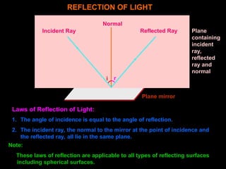
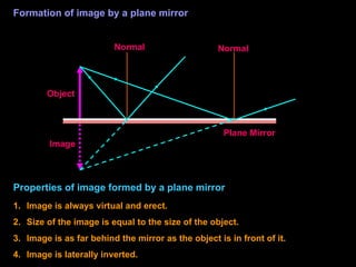
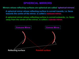
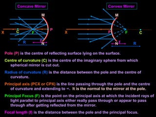
The document discusses the properties and behavior of light, including concepts such as reflection, image formation by mirrors (concave and convex), and the wave and particle nature of light. It outlines the laws of reflection, the characteristics of images formed by mirrors, and practical applications of different types of mirrors. Additionally, it covers sign conventions for spherical mirrors and provides formulas for mirror image distances and magnification.

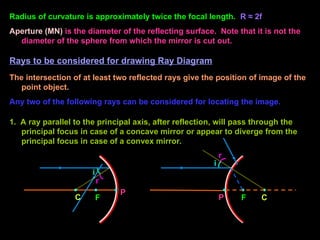
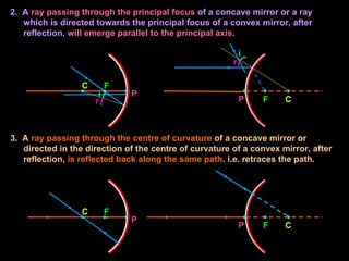
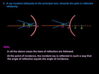
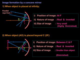


![[Abhay Pratap Singh ] REFLECTION PPT[1].pptx](https://cdn.slidesharecdn.com/ss_thumbnails/abhaypratapsinghreflectionppt1-250104031916-5918ff92-thumbnail.jpg?width=640&height=640&fit=bounds)


