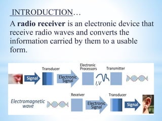
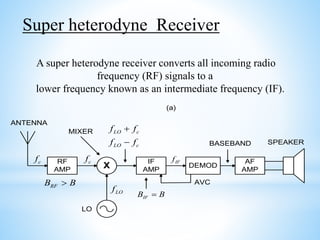
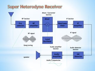
Presented by;
Deep A Patel
Sem : 5th
Content…
INTRODUCTION…
A radio receiver is an electronic device that
receive radio waves and converts the
information carried by them to a usable
form.
• Select desired signal and reject unwanted
signal
• Amplify the R.F. signal
• Demodulate the selected signal
FUNCTION
Simplicity of operation
Good fidelity
Good selectivity
Average sensitivity
If receiver has poor selectivity…….
 It refers to the
ability of a receiver
to select a signal of
desired frequency
while reject all
others.
 The bandwidth of a tuned circuit is
a measure of the selectivity
If receiver has poor sensitivity….
The ability of receiver to detect the weakest
possible signal is known as sensitivity
If receiver has poor fidelity…
The ability of receiver to reproduce faithfully all
the frequency components in the baseband signal is
called fidelity
TYTES OF RADIO RECEIVERS….
Super heterodyne Receiver
Tuned Radio Frequency (T.R.F) Receiver
AM Receiver
FM Receiver
SPEAKER
RF
AMP
ANTENNA
X
IF
AMP
DEMOD
AF
AMP
MIXER
cf cf
LO c
LO c
f f
f f
+
-
IFf
LOfRFB B>
IFB B=
AVC
LO
BASEBAND
(a)
Super heterodyne Receiver
A super heterodyne receiver converts all incoming radio
frequency (RF) signals to a
lower frequency known as an intermediate frequency (IF).
Pre
selector
RF
amplifier
Mixer
IF
Amplifier
Band pass
filter
AM
Detector
Audio
Amplifier
Local
Oscillator
Mixer / Converter
Section
RF Section IF Section
Audio detector
Section
Audio amplifier
Section
speaker
Gang tuning
RF signal
IF signal
Audio Frequencies
Heterodyne receiver has five sections
RF section
Mixer/converter section
IF section
Audio detector section
Audio amplifier section
Preselected stage
Broad tuned band pass filter with adjustable frequency that is tuned to
carrier frequency
Provide initial band limiting to prevent specific unwanted radio
frequency called image frequency from entering into receiver.
Reduces the noise bandwidth of the receiver and provides the initial
step toward reducing the over all receiver bandwidth to the minimum
bandwidth required to pass the information signal.
RF section
It determines the sensitivity of the receiver.
RF amplifier is the first active device in the network it is
the primary contributor to the noise. And it is the
predominant factor in determining the noise figure.
Receiver may have one or more RF amplifier depending
on the desired sensitivity.
Amplifier stage
Greater gain and better sensitivity
Improved image frequency rejection
Better signal to noise ratio
Better selectivity.
Due to RF amplifier
It consists of two components
Mixer
Local oscillator
Mixer stage :
Heterodyning takes place in the mixer stage.
Radio frequencies are down converted to intermediate frequency
Carrier and sidebands are translated to high frequencies without
effecting the envelope of message signal.
Mixer or conversion section
Local oscillator
frequency is tuned above
RF
High side injection Low side injection
Local oscillator
frequency is tuned below
RF
f LO = fRf + fIF f LO = fRf - fIF
Frequency conversion
 The difference between the RF and Local oscillator frequency is
always constant IF.
RF-to-IF conversion
Preselector
535 - 565
kHz
Mixer
IF filter
450 – 460
kHz
Oscillator
1005 kHz
Receiver RF input (535 – 1605 kHz)
565 kHz535 545 555
470 kHz440 450 460
450 460 kHz IF Filter output
high-side
injection
(fLO > fRF)
lo RF IFf f f= +
 TRACKING:
It is the ability of the local oscillator in a receiver to oscillate either above or
below the selected radio frequency carrier by an amount equal to the IF frequency
through the entire radio frequency band.
 Tracking error: the difference between the actual local oscillator frequency
to the desired frequency.
 The maximum tracking error 3KHz + or -.
 Tracking error can be reduced by using three point tracking.
 The preselector and local oscillator each have trimmer capacitor in parallel
with primary tuning capacitor that compensates for minor tracking errors in
the high end of AM spectrum.
 The local oscillator has additional padder capacitor in series with the
tuning coil that compensates for minor tracking errors at the low end of
AM spectrum.
Image frequency : It is any frequency other than the selected radio
frequency carrier that is allowed to enter into the
receiver and mix with the local oscillator will
produce cross product frequencies that is equal to
the intermediate frequency.
flo =fsi+fif → fsi=flo-fif when signal frequency is mixed with oscillator
frequency one of the by products is the difference frequency which is
passed to the amplifier in the IF stage.
The frequency fim= flo+fsi the image frequency will also produce fsi
when mixed with fo .
For better image frequency rejection a high IF is preferred.
If intermediate frequency is high it is very difficult to design stable
amplifiers.
LORF
SF
IF IM
fif fif
2fif
frequency
Image frequency rejection ratio
It is the numerical measure of the ability of the preselector to reject the image frequency.
Single tuned amplifier the ratio of the gain at the desired RF to the gain at the image
frequency.






-





=
+=
im
RF
RF
im
f
f
f
f
QIFRR

22
1(
If the IF is too high
 Poor Selectivity and Poor adjacent channel rejection.
 Tracking Difficulties.
If the IF is too low
 Image frequency rejection becomes poorer.
 Selectivity too sharp and cutting off sidebands
 Instability of oscillator will occur.
 It contains detector and AGC or AVC
 Detector: Rectifies the modulated signal, then filters out the
455 KHz. Leaving only the audio frequency or intelligence of
50 Hz – 20 KHz Which is sent to the AF amplifiers.
 Automatic Volume Control or gain control is taken at the
detector (demodulated and fed back to the first IF amplifier
base). Required to overcome atmospheric and terrain
conditions that adversely affect signal strength between the
transmitter & receiver.
The resultant audio signal is amplified in this section
and fed into the
output device(ex: loudspeaker)……
In this section we have
 Audio preamp stage
 Audio driver stage
 Audio push pull stage
 If the receiver gain is const. then receiver o/p will fluctuate
according to the strength of i/p signal.& this is not desirable .
 AGC is used to adjust the receiver gain automatically so as to
keep the receiver O/P constant irrespective of the strength of
I/P Signal.
Automatic gain control (A.G.C)
Advantages of SHRR
 No variation in bandwidth. It remains constant
over the entire frequency range.
 High selectivity & sensitivity
 High adjacent channel rejection
Frequency range
A radio receiver may be designed to tune to a fixed frequency,
MF AM broadcast band, 535 kHz - 1605 kHz
General coverage MF/HF communications receiver 100 kHz - 30
MHz
VHF FM broadcast band, 88 - 108 MHz
UHF TV broadcast band (analogue or digital) 470 - 860 MHz
Scanning receiver 0.5 MHz - 1300 MHz
GSM 900, GSM1800 or 3G mobile phone bands
Wireless LAN band 2400 - 2483.5 MHz
The super heterodyne receiver concept is the basis
for most modern receiver designs.
The selectivity of a super heterodyne receiver is
established in the IF stage.
Tuning of a super heterodyne receiver consists of
tuning the LO such that the desired mixer output
falls in the center of the IF band.
Radio receivers,dp

Radio receivers,dp

  • 1.
    Presented by; Deep APatel Sem : 5th
  • 2.
  • 3.
    INTRODUCTION… A radio receiveris an electronic device that receive radio waves and converts the information carried by them to a usable form.
  • 4.
    • Select desiredsignal and reject unwanted signal • Amplify the R.F. signal • Demodulate the selected signal FUNCTION
  • 5.
    Simplicity of operation Goodfidelity Good selectivity Average sensitivity
  • 6.
    If receiver haspoor selectivity…….  It refers to the ability of a receiver to select a signal of desired frequency while reject all others.  The bandwidth of a tuned circuit is a measure of the selectivity
  • 7.
    If receiver haspoor sensitivity…. The ability of receiver to detect the weakest possible signal is known as sensitivity
  • 8.
    If receiver haspoor fidelity… The ability of receiver to reproduce faithfully all the frequency components in the baseband signal is called fidelity
  • 9.
    TYTES OF RADIORECEIVERS…. Super heterodyne Receiver Tuned Radio Frequency (T.R.F) Receiver AM Receiver FM Receiver
  • 10.
    SPEAKER RF AMP ANTENNA X IF AMP DEMOD AF AMP MIXER cf cf LO c LOc f f f f + - IFf LOfRFB B> IFB B= AVC LO BASEBAND (a) Super heterodyne Receiver A super heterodyne receiver converts all incoming radio frequency (RF) signals to a lower frequency known as an intermediate frequency (IF).
  • 11.
    Pre selector RF amplifier Mixer IF Amplifier Band pass filter AM Detector Audio Amplifier Local Oscillator Mixer /Converter Section RF Section IF Section Audio detector Section Audio amplifier Section speaker Gang tuning RF signal IF signal Audio Frequencies
  • 12.
    Heterodyne receiver hasfive sections RF section Mixer/converter section IF section Audio detector section Audio amplifier section
  • 13.
    Preselected stage Broad tunedband pass filter with adjustable frequency that is tuned to carrier frequency Provide initial band limiting to prevent specific unwanted radio frequency called image frequency from entering into receiver. Reduces the noise bandwidth of the receiver and provides the initial step toward reducing the over all receiver bandwidth to the minimum bandwidth required to pass the information signal. RF section
  • 14.
    It determines thesensitivity of the receiver. RF amplifier is the first active device in the network it is the primary contributor to the noise. And it is the predominant factor in determining the noise figure. Receiver may have one or more RF amplifier depending on the desired sensitivity. Amplifier stage
  • 15.
    Greater gain andbetter sensitivity Improved image frequency rejection Better signal to noise ratio Better selectivity. Due to RF amplifier
  • 16.
    It consists oftwo components Mixer Local oscillator Mixer stage : Heterodyning takes place in the mixer stage. Radio frequencies are down converted to intermediate frequency Carrier and sidebands are translated to high frequencies without effecting the envelope of message signal. Mixer or conversion section
  • 17.
    Local oscillator frequency istuned above RF High side injection Low side injection Local oscillator frequency is tuned below RF f LO = fRf + fIF f LO = fRf - fIF Frequency conversion  The difference between the RF and Local oscillator frequency is always constant IF.
  • 18.
    RF-to-IF conversion Preselector 535 -565 kHz Mixer IF filter 450 – 460 kHz Oscillator 1005 kHz Receiver RF input (535 – 1605 kHz) 565 kHz535 545 555 470 kHz440 450 460 450 460 kHz IF Filter output high-side injection (fLO > fRF) lo RF IFf f f= +
  • 19.
     TRACKING: It isthe ability of the local oscillator in a receiver to oscillate either above or below the selected radio frequency carrier by an amount equal to the IF frequency through the entire radio frequency band.
  • 20.
     Tracking error:the difference between the actual local oscillator frequency to the desired frequency.  The maximum tracking error 3KHz + or -.  Tracking error can be reduced by using three point tracking.  The preselector and local oscillator each have trimmer capacitor in parallel with primary tuning capacitor that compensates for minor tracking errors in the high end of AM spectrum.  The local oscillator has additional padder capacitor in series with the tuning coil that compensates for minor tracking errors at the low end of AM spectrum.
  • 21.
    Image frequency :It is any frequency other than the selected radio frequency carrier that is allowed to enter into the receiver and mix with the local oscillator will produce cross product frequencies that is equal to the intermediate frequency. flo =fsi+fif → fsi=flo-fif when signal frequency is mixed with oscillator frequency one of the by products is the difference frequency which is passed to the amplifier in the IF stage. The frequency fim= flo+fsi the image frequency will also produce fsi when mixed with fo . For better image frequency rejection a high IF is preferred. If intermediate frequency is high it is very difficult to design stable amplifiers.
  • 22.
    LORF SF IF IM fif fif 2fif frequency Imagefrequency rejection ratio It is the numerical measure of the ability of the preselector to reject the image frequency. Single tuned amplifier the ratio of the gain at the desired RF to the gain at the image frequency.       -      = += im RF RF im f f f f QIFRR  22 1(
  • 23.
    If the IFis too high  Poor Selectivity and Poor adjacent channel rejection.  Tracking Difficulties. If the IF is too low  Image frequency rejection becomes poorer.  Selectivity too sharp and cutting off sidebands  Instability of oscillator will occur.
  • 24.
     It containsdetector and AGC or AVC  Detector: Rectifies the modulated signal, then filters out the 455 KHz. Leaving only the audio frequency or intelligence of 50 Hz – 20 KHz Which is sent to the AF amplifiers.  Automatic Volume Control or gain control is taken at the detector (demodulated and fed back to the first IF amplifier base). Required to overcome atmospheric and terrain conditions that adversely affect signal strength between the transmitter & receiver.
  • 25.
    The resultant audiosignal is amplified in this section and fed into the output device(ex: loudspeaker)…… In this section we have  Audio preamp stage  Audio driver stage  Audio push pull stage
  • 26.
     If thereceiver gain is const. then receiver o/p will fluctuate according to the strength of i/p signal.& this is not desirable .  AGC is used to adjust the receiver gain automatically so as to keep the receiver O/P constant irrespective of the strength of I/P Signal. Automatic gain control (A.G.C)
  • 27.
    Advantages of SHRR No variation in bandwidth. It remains constant over the entire frequency range.  High selectivity & sensitivity  High adjacent channel rejection
  • 28.
    Frequency range A radioreceiver may be designed to tune to a fixed frequency, MF AM broadcast band, 535 kHz - 1605 kHz General coverage MF/HF communications receiver 100 kHz - 30 MHz VHF FM broadcast band, 88 - 108 MHz UHF TV broadcast band (analogue or digital) 470 - 860 MHz Scanning receiver 0.5 MHz - 1300 MHz GSM 900, GSM1800 or 3G mobile phone bands Wireless LAN band 2400 - 2483.5 MHz
  • 29.
    The super heterodynereceiver concept is the basis for most modern receiver designs. The selectivity of a super heterodyne receiver is established in the IF stage. Tuning of a super heterodyne receiver consists of tuning the LO such that the desired mixer output falls in the center of the IF band.