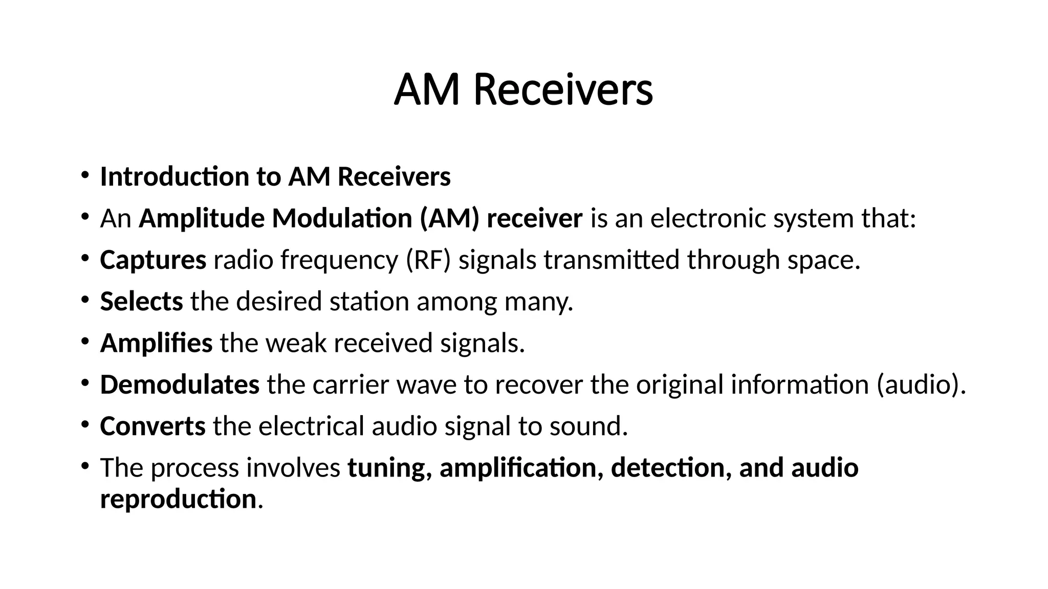
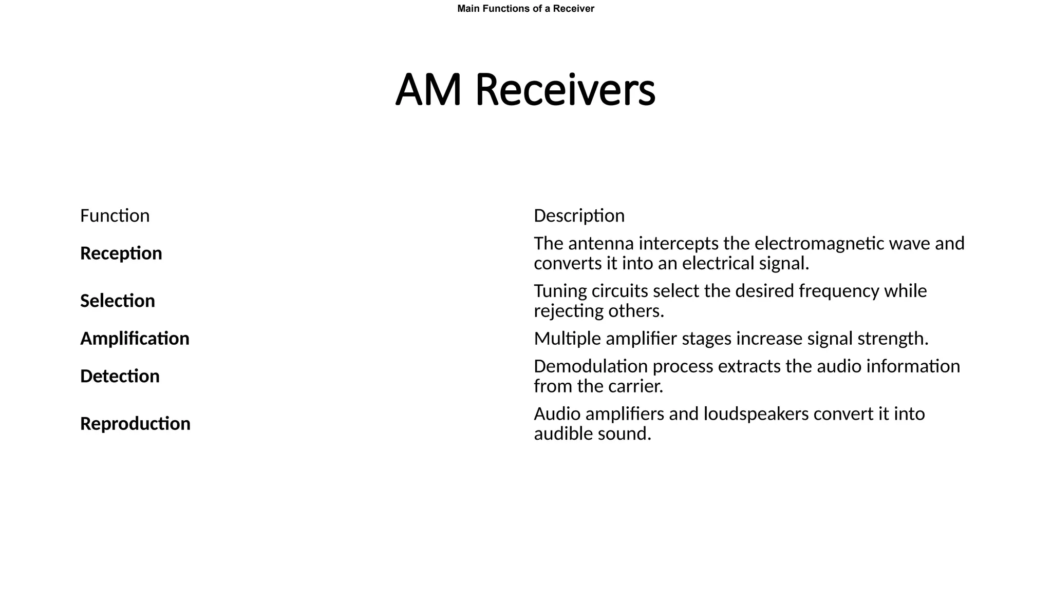
An AM receiver is an electronic system designed to capture radio frequency (RF) signals transmitted through space, select a single desired station from among many, amplify the weak received signals, demodulate the carrier wave to recover the original audio information, and convert that electrical audio signal into sound. The overall operation of an AM receiver revolves around four essential stages: reception, selection, amplification, demodulation, and reproduction. In reception, the antenna intercepts the electromagnetic wave and converts it into a small electrical signal. The selection stage uses tuning circuits to isolate the carrier frequency of the intended station while rejecting adjacent signals. Amplification follows, with multiple amplifier stages boosting signal strength to overcome noise and distortion. The detection stage then demodulates the amplified RF signal to recover the modulating audio signal, which is subsequently rendered audible by the audio amplifier and loudspeaker in the reproduction stage.
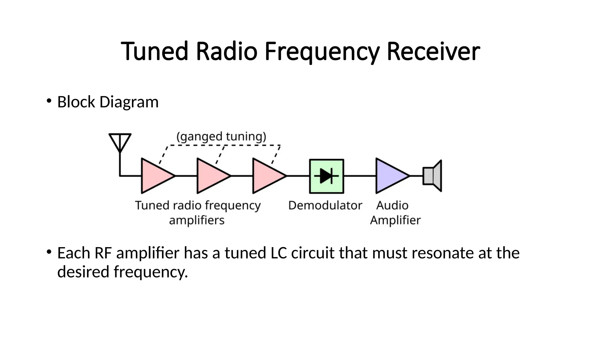
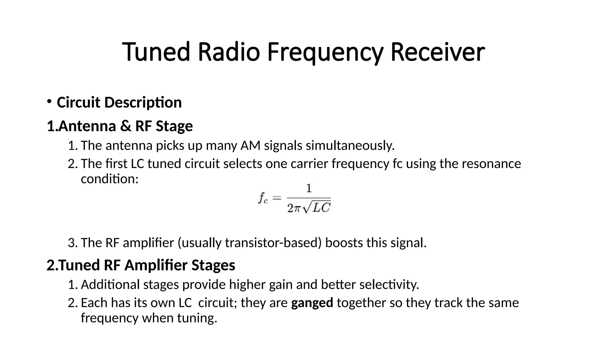
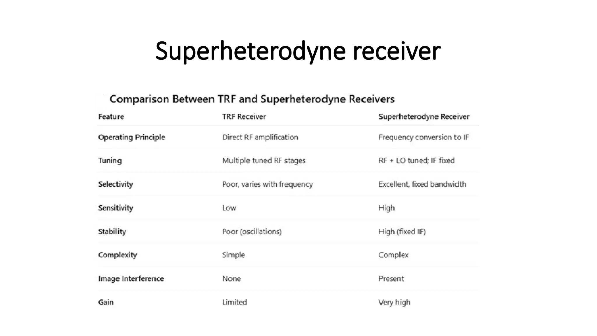
AM receivers are broadly classified into two architectural families: Tuned Radio Frequency (TRF) receivers and Superheterodyne receivers. The TRF receiver directly amplifies the incoming modulated RF signal using several tuned RF amplifier stages before demodulation. Each stage is tuned to the carrier frequency of the target station, so amplification tracks that frequency and its sidebands. A block diagram of a TRF design shows RF amplifiers with tuned LC circuits that resonate at the desired frequency. The detailed circuit description begins with the antenna and RF stage, where the first LC tuned circuit selects the carrier frequency through resonance, followed by a transistor-based RF amplifier. Additional RF amplifier stages provide higher gain and improved selectivity, with each stage maintaining resonance alignment across the tuned frequency by ganging LC circuits together.
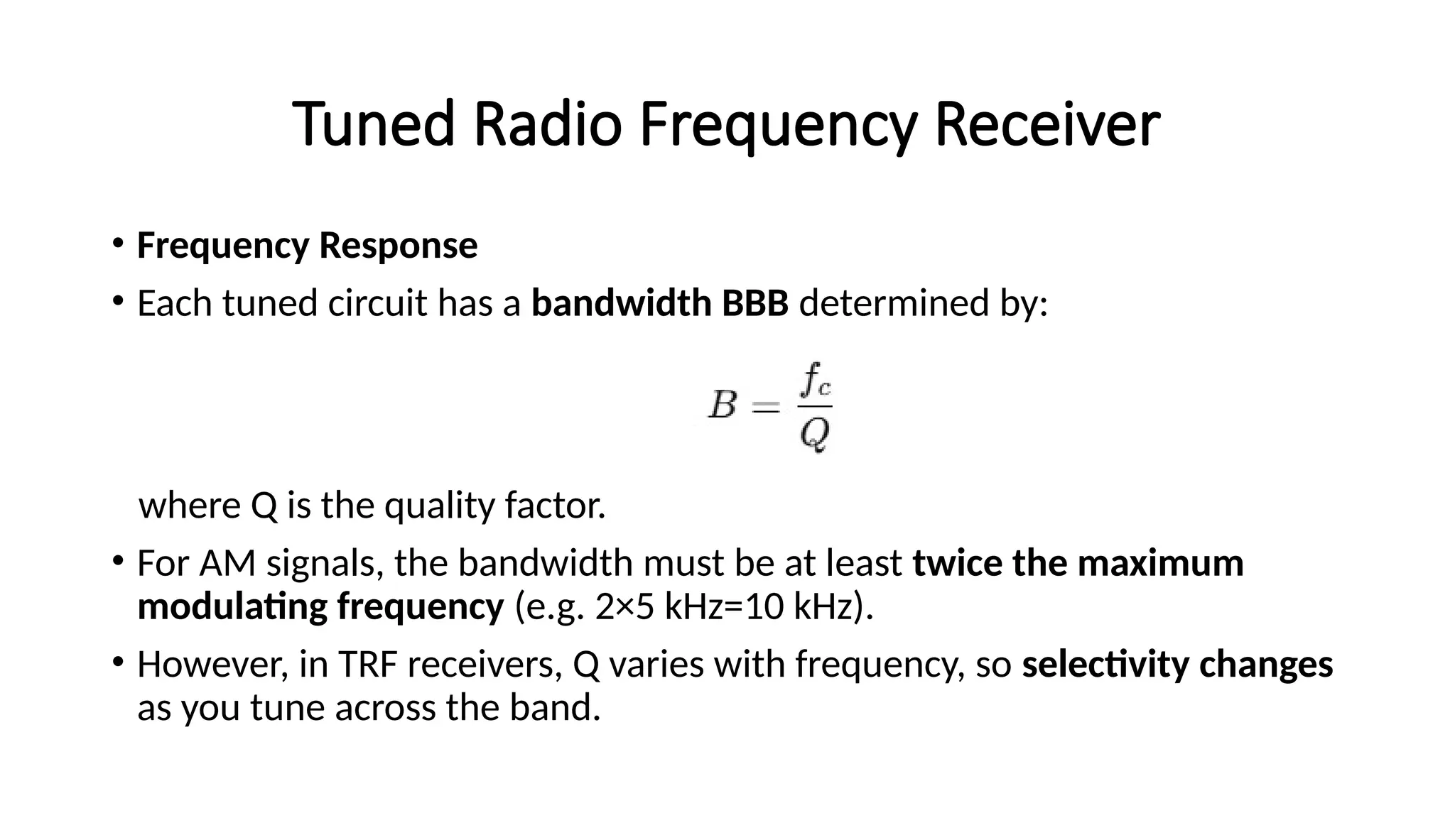
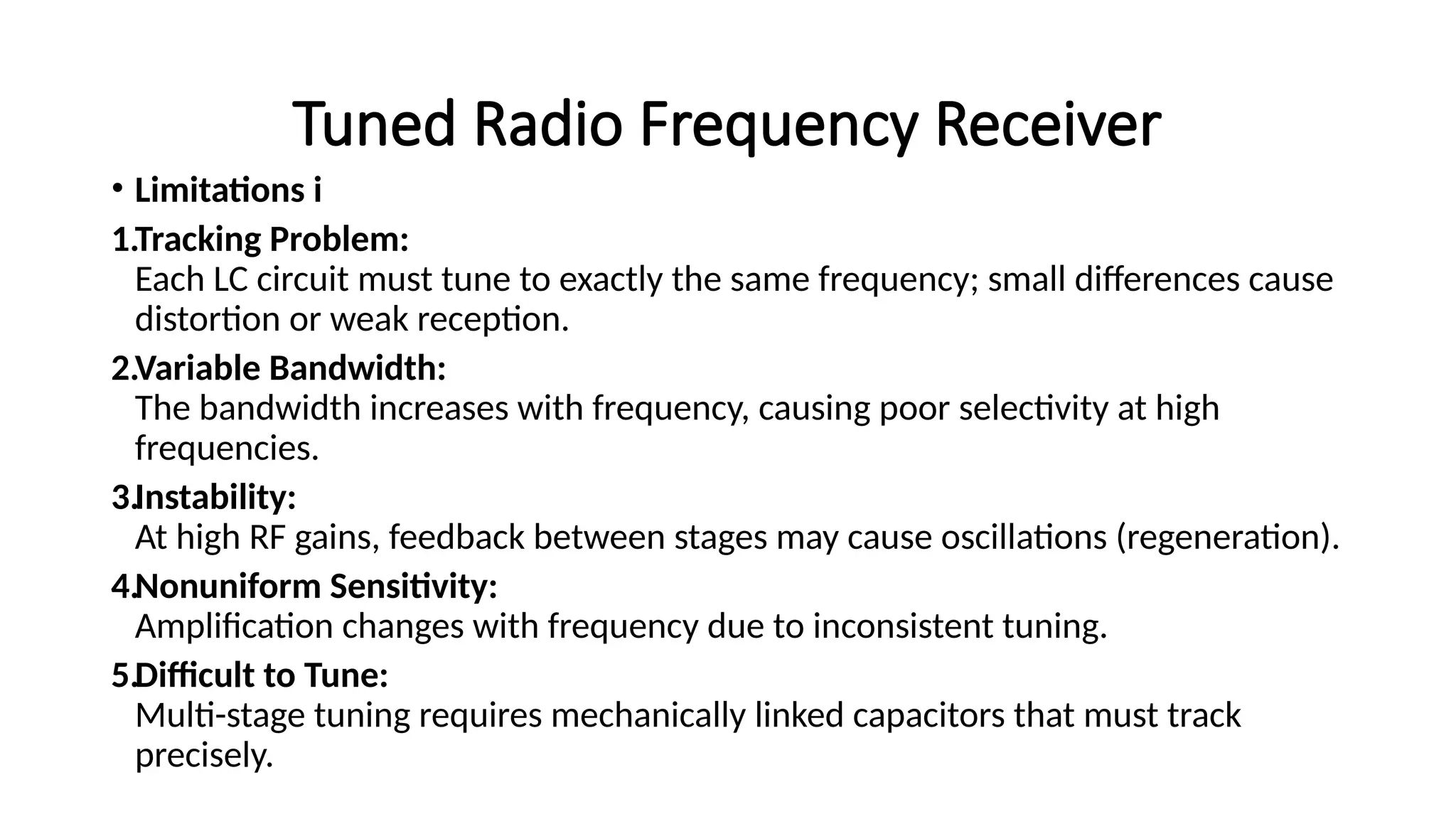
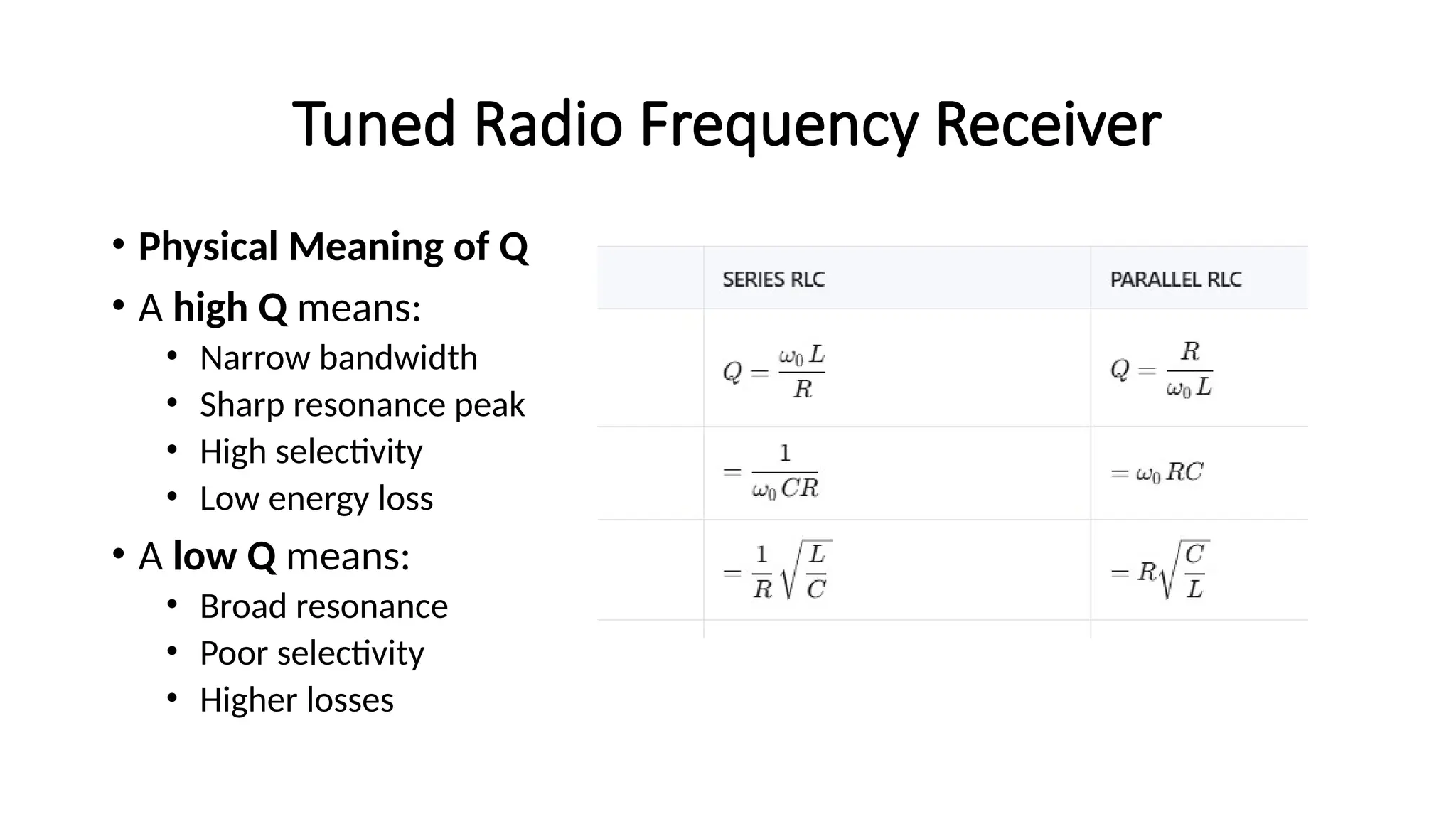
In the detector stage, the amplified RF is demodulated by a diode envelope detector, producing the original modulating signal, which is then fed to the audio amplifier and speaker. The frequency response of a TRF receiver depends on the bandwidth of each tuned circuit, typically defined by the quality factor Q. The bandwidth must accommodate the maximum modulating frequency, for example, 2 × 5 kHz = 10 kHz for standard AM, though Q varies with frequency, causing selectivity to change as tuning traverses the band. Several practical limitations of TRF receivers are noted: tracking problems require exact alignment of all LC circuits, variable bandwidth causes poorer selectivity at higher frequencies, potential instability from regenerative feedback at high RF gains, nonuniform sensitivity across frequencies due to uneven tuning, and complexity in tuning because mechanically linked capacitors must track precisely.
A high Q indicates narrow bandwidth, a sharp resonance peak, high selectivity, and low energy loss, whereas a low Q indicates broad resonance, poorer