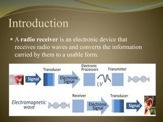
This document discusses the history and types of radio receivers. It describes how the earliest radio receiver was created in 1896 by Alexander Popov and was based on Maxwell's discovery of electromagnetic waves. There are three main types of receivers discussed - crystal radios, tuned radio frequency receivers, and superheterodyne receivers. Crystal radios require no power source beyond the radio waves themselves, while tuned radio frequency receivers have individually tuned amplifier stages and superheterodyne receivers mix signals to extract an intermediate frequency. The document also covers frequency ranges, sensitivity, selectivity and how radio waves propagate.
RF Carrier oscillator
To generate the carrier signal.
Usually a crystal-controlled oscillator is used.
Buffer amplifier
Low gain, high input impedance linear amplifier.
To isolate the oscillator from the high power amplifiers.
Modulator : can use either emitter collector modulation
Intermediate and final power amplifiers (pull-push modulators)
Required with low-level transmitters to maintain symmetry in the AM envelope
Coupling network
Matches output impedance of the final amplifier to the transmission line/antenn
Applications are in low-power, low-capacity systems : wireless intercoms, remote control units, pagers and short-range walkie-talkie
Modulating signal is processed similarly as in low-level transmitter except for the addition of power amplifier
Power amplifier
To provide higher power modulating signal necessary to achieve 100% modulation (carrier power is maximum at the high-level modulation point).
Same circuit as low-level transmitter for carrier oscillator, buffer and driver but with addition of power amplifier
By completing this presentation will be have a clear idea about Antenna's working principles, Antenna's Types & Antenna's Parameters. At the end to this document you'll have a brief idea about Antenna's Tilt vs Distance Calculation & Cluster wise optimum Antenna Selection procedure. Impact of antenna PIM & VSWR have been described elaborately in this document as well.
A horn antenna or microwave horn is an antenna that consists of a flaring metal waveguide shaped like a horn to direct radio waves in a beam. Horns are widely used as antennas at UHF and microwave frequencies, above 300 MHz.
hello readers i give my PPT presentation for about antenna and ther properties and working explain in this ppt
i hope you like it THANK YOU.......!!!!!!!
Use principles of reflection and refraction to describe how lenses and mirrors work.
**More good stuff available at:
www.wsautter.com
and
http://www.youtube.com/results?search_query=wnsautter&aq=f
Everything you want to know about Liquid LensesLikan Patra
Liquid lens technology has a wide range of applications. Because the liquid lens is so small, light and inexpensive, it can easily be incorporated into a variety of objects. Soon every laptop might come with a built in webcam made from a liquid lens. One of the few disadvantages of a liquid lens made with water is that it is subject to freezing at low temperatures. If you have a cell phone or camera with a liquid lens, be careful not to expose it to very cold temperatures for long periods of time, or you could damage your liquid lens by freezing the water inside it.
The slides are contained with different types of radio receivers & its mechanisms as well as advantages,disadvantages of these radio receivers on different purposes. I think everyone will get basic knowledge on that. Thanks
ALL INDIA RADIO LATEST 2017 BY ABHISHEK BAGVAAbhishek Bagva
HELLO .......
ABHISHEK BAGVA HERE FROM GONDIA, MAHARASHTRA .. IN THIS PPT I'VE REVEALED MANY TOPIC THAT HAS BEEN TAUGHT TO US IN ALL INDIA RADIO STATION BALAGHAT, MP.
I HOPE U MAY LIKE IT.
#FOLLOW_ME
FB: https://www.facebook.com/abbishek.bagva
INSTAGRAM: https://www.instagram.com/k33psilent_its_fuga/
Model Attribute Check Company Auto PropertyCeline George
In Odoo, the multi-company feature allows you to manage multiple companies within a single Odoo database instance. Each company can have its own configurations while still sharing common resources such as products, customers, and suppliers.
Unit 8 - Information and Communication Technology (Paper I).pdfThiyagu K
This slides describes the basic concepts of ICT, basics of Email, Emerging Technology and Digital Initiatives in Education. This presentations aligns with the UGC Paper I syllabus.
Ethnobotany and Ethnopharmacology:
Ethnobotany in herbal drug evaluation,
Impact of Ethnobotany in traditional medicine,
New development in herbals,
Bio-prospecting tools for drug discovery,
Role of Ethnopharmacology in drug evaluation,
Reverse Pharmacology.
Synthetic Fiber Construction in lab .pptxPavel ( NSTU)
Synthetic fiber production is a fascinating and complex field that blends chemistry, engineering, and environmental science. By understanding these aspects, students can gain a comprehensive view of synthetic fiber production, its impact on society and the environment, and the potential for future innovations. Synthetic fibers play a crucial role in modern society, impacting various aspects of daily life, industry, and the environment. ynthetic fibers are integral to modern life, offering a range of benefits from cost-effectiveness and versatility to innovative applications and performance characteristics. While they pose environmental challenges, ongoing research and development aim to create more sustainable and eco-friendly alternatives. Understanding the importance of synthetic fibers helps in appreciating their role in the economy, industry, and daily life, while also emphasizing the need for sustainable practices and innovation.
The Indian economy is classified into different sectors to simplify the analysis and understanding of economic activities. For Class 10, it's essential to grasp the sectors of the Indian economy, understand their characteristics, and recognize their importance. This guide will provide detailed notes on the Sectors of the Indian Economy Class 10, using specific long-tail keywords to enhance comprehension.
For more information, visit-www.vavaclasses.com
Read| The latest issue of The Challenger is here! We are thrilled to announce that our school paper has qualified for the NATIONAL SCHOOLS PRESS CONFERENCE (NSPC) 2024. Thank you for your unwavering support and trust. Dive into the stories that made us stand out!
2024.06.01 Introducing a competency framework for languag learning materials ...Sandy Millin
http://sandymillin.wordpress.com/iateflwebinar2024
Published classroom materials form the basis of syllabuses, drive teacher professional development, and have a potentially huge influence on learners, teachers and education systems. All teachers also create their own materials, whether a few sentences on a blackboard, a highly-structured fully-realised online course, or anything in between. Despite this, the knowledge and skills needed to create effective language learning materials are rarely part of teacher training, and are mostly learnt by trial and error.
Knowledge and skills frameworks, generally called competency frameworks, for ELT teachers, trainers and managers have existed for a few years now. However, until I created one for my MA dissertation, there wasn’t one drawing together what we need to know and do to be able to effectively produce language learning materials.
This webinar will introduce you to my framework, highlighting the key competencies I identified from my research. It will also show how anybody involved in language teaching (any language, not just English!), teacher training, managing schools or developing language learning materials can benefit from using the framework.
The French Revolution, which began in 1789, was a period of radical social and political upheaval in France. It marked the decline of absolute monarchies, the rise of secular and democratic republics, and the eventual rise of Napoleon Bonaparte. This revolutionary period is crucial in understanding the transition from feudalism to modernity in Europe.
For more information, visit-www.vavaclasses.com
How to Make a Field invisible in Odoo 17Celine George
It is possible to hide or invisible some fields in odoo. Commonly using “invisible” attribute in the field definition to invisible the fields. This slide will show how to make a field invisible in odoo 17.
2. Contents
Introduction
History
Types Of Radio Receiver
Sensitivity and Selectivity
Frequency range
3. Introduction
A radio receiver is an electronic device that
receives radio waves and converts the information
carried by them to a usable form.
4. History
Alexander Stepanovich Popov
First radio receiver in 1896.
It was based on electromagnetic waves,
which were proven to exist by James Clerk Maxwell
only a few years earlier in 1887.
5. Types Of Radio Receiver
Crystal radio receiver
Tuned radio frequency receiver
Superheterodyne Receiver
6. Crystal radio
A crystal radio is the simplest kind of radio
It needs no battery or power source
It gets all of its power only from the radio wave.
7. Components of Crystal Radio
Antenna
Tuner
Coil
Ground wire
Detector
Capacitor
Diode
9. Tuned radio frequency receiver
one or more tuned radio frequency (RF)
individually tuned to the station's frequency
10. Tuned Radio Frequency Receiver
A tuned radio frequency receiver (or TRF receiver)
is a type of radio receiver that is usually composed of
one or more tuned radio frequency (RF) amplifier
stages followed by a detector (demodulator) circuit to
extract the audio signal and an audio frequency
amplifier. Popular in the 1920s, it could be tedious to
operate because each stage must be individually tuned
to the station's frequency. By the mid 1930s it was
replaced by the superheterodyne receiver invented by
Edwin Armstrong.
11.
12. How it works
The classic TRF receivers of the 1920s and 30s
consisted of three sections:
One or more tuned RF amplifier stages. These amplify
the signal of the desired station to a level sufficient to
drive the detector, while rejecting all other signals
picked up by the antenna
a detector, which extracts the audio (modulation)
signal from the radio carrier signal by rectifying it
optionally, but almost always included, one or more
audio amplifier stages which increase the power of the
audio signal.
13. Advantages and disadvantages
Disadvantage.
Since they used inductor and capacitor as tunning the
element, the circuit is bulky and costly.
They are not suitable to amplify audio frequencies
If the band of the frequency is increased, design
become complex.
14. Advantages and disadvantages
Advantages
They amplify defined frequency.
Signal to noise ratio at output is good.
They are well suited for radio transmitters and receiver.
The band of frequency over which amplification is
required can be varied.
16. Architecture of
Superheterodyne Receiver
Antenna
The antenna pick up all radiated signal and feeds them into
the RF(Amplifier) .These signal are very small (usually only
a few microvolts).
17. RF(Amplifier)
This circuit can be adjusted (tuned) to select and amplify
any carries frequency within the AM Broad cost band .
Only the selected frequency and its two side bands pass
through the amplifier.(Some AM Receiver don’t have a
Separate RF amplifier stage.)
18. Local Oscillator
This circuit generates a steady sine
wave at a frequency 455 khz above
the selected RF
20. IF Amplifier
Increase the level of the signal .
Demodulation
The received signal is now processed by
the demodulator stage where the audio signal (or
other baseband signal) is recovered and then further
amplified.
Audio Amplifier
This circuit amplifies the detected audio signal and
drive the speaker to drive sound
21. Sensitivity and Selectivity
Sensitivity
Weak signal
noise
Selectivity
Band width filter
1% of RC Frequency
22. How radio waves travel.
Although radio waves are sometimes colloquially referred to as
"airwaves", they do not require air or any other medium in
which to travel and can travel through a vacuum.
Like light waves, radio waves travel in straight lines unless
something reflects or refracts them. Like light waves, radio
waves may be obstructed by obstacles, which can cast a radio
"shadow". Although radio waves can pass through many non-conductive
material without much loss, they do suffer some
loss when passing through walls, floors and roofs. This loss
depends upon the building materials used and increases at
higher frequencies. Metal, water, ground and other electrically
conductive materials cause large losses to radio waves passing
through them and in some cases no usable signal may pass
through.
23. Frequency range
A radio receiver may be designed to tune to a fixed frequency,
MF AM broadcast band, 535 kHz - 1605 kHz
General coverage MF/HF communications receiver 100 kHz -
30 MHz
VHF FM broadcast band, 88 - 108 MHz
UHF TV broadcast band (analogue or digital) 470 - 860 MHz
Scanning receiver 0.5 MHz - 1300 MHz
GSM 900, GSM1800 or 3G mobile phone bands
Wireless LAN band 2400 - 2483.5 MHz