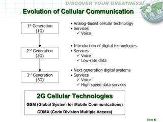
Slide #1
Mobile
Communication
Instructor: Swarup Sinha Ray
Slide #2
Learning ObjectivesLearning Objectives
• To support you to refresh the basics of cellularTo support you to refresh the basics of cellular
technologiestechnologies
• To know the scope of functioning in cellularTo know the scope of functioning in cellular
environmentenvironment
• To explain the technical aspects of cellularTo explain the technical aspects of cellular
telecommunicationstelecommunications
Slide #3
Course AgendaCourse Agenda
– Access Method & Wireless AccessAccess Method & Wireless Access
– Multiple AccessMultiple Access
– Mobile ServiceMobile Service
– Evolution of Cellular CommunicationEvolution of Cellular Communication
– GSM BasicsGSM Basics
– Mobile NetworkMobile Network
– Cellular Telephony in IndiaCellular Telephony in India
– CDMA BasicsCDMA Basics
– CDMA vs GSMCDMA vs GSM
– Wireless in Local LoopWireless in Local Loop
– Mobile Data (3G)Mobile Data (3G)
Slide #4
Access MethodsAccess Methods
WIRELINEWIRELINE
• CopperCopper
– Local Loop 2 Wire (analog)Local Loop 2 Wire (analog) e.g. Plain Old Telephone systeme.g. Plain Old Telephone system
– Local Loop 4 Wire (digital)Local Loop 4 Wire (digital) e.g. E1 line, E3 linee.g. E1 line, E3 line
• Optic FiberOptic Fiber
• ModemModem
– OpticalOptical
– ISDN BRIISDN BRI
– Digital Subscriber Line (DSL - 2 wire)Digital Subscriber Line (DSL - 2 wire)
WIRELESSWIRELESS
• MicrowaveMicrowave
– LMDS – Local Multichannel Distribution ServiceLMDS – Local Multichannel Distribution Service
– MMDS – Multipoint/Microwave Multichannel Distribution ServiceMMDS – Multipoint/Microwave Multichannel Distribution Service
– UBR – Unlicensed Band Radio LinkUBR – Unlicensed Band Radio Link
• VSAT =VSAT = Very Small Aperture TerminalVery Small Aperture Terminal
• CellularCellular
– GSMGSM
– CDMA 2000 1xCDMA 2000 1x
• Wi-MAX, Wi-FiWi-MAX, Wi-Fi
Slide #5
Electromagnetic WaveElectromagnetic Wave
• Light (Optic Fiber Cable)Light (Optic Fiber Cable)
• Infrared for device to device data transferInfrared for device to device data transfer
• MicrowaveMicrowave
– VSAT (Very Small Aperture Terminal) + SatelliteVSAT (Very Small Aperture Terminal) + Satellite
– LMDS (Local Multichannel Distribution system)LMDS (Local Multichannel Distribution system)
– MMDS (Multipoint Multichannel Distribution system)MMDS (Multipoint Multichannel Distribution system)
– WiMAXWiMAX (Worldwide Interoperability for Microwave Access)(Worldwide Interoperability for Microwave Access)
• RadioRadio
– UBRS (Unlicensed Band Radio system) (2.4 GHz)UBRS (Unlicensed Band Radio system) (2.4 GHz)
– WiFi (Wireless Fidelity) (2.4 GHz)WiFi (Wireless Fidelity) (2.4 GHz)
– Cordless / Walkie TalkieCordless / Walkie Talkie
– Cellular (450 MHz, 800MHz, 900 MHz, 1.8 GHz, 1.9 GHz)Cellular (450 MHz, 800MHz, 900 MHz, 1.8 GHz, 1.9 GHz)
2.5 GHz / 2.7 GHz
3.3 GHz / 3.5 GHz
5.2 GHz / 5.7 GHz
10.5 GHz
24.5 GHz / 26 GHz
54 GHz / 66 GHz
2.5 GHz / 2.7 GHz
3.3 GHz / 3.5 GHz
5.2 GHz / 5.7 GHz
10.5 GHz
24.5 GHz / 26 GHz
54 GHz / 66 GHz
Slide #6
Multiple AccessMultiple Access
To share communication channels or physical communication
mediums (air interface in case of wireless) between multiple users
Multiple access techniques developed due to Digital technology
Slide #7
Frequency & Time Division Multiple Access
• User’s channel is specific RF channel
• Multiple users access each channel w/o
interference
• Each user is allocated unique time slots
within each channel
• Current cellular standard divides signals
into 6 time slots
• Each signal uses 2 slots, hence allowing 3
signals per channel
• Hence the channel belongs to the user
during the time slots in a repeating
sequence
• Problem of bandwidth wastage if no signal
Time
Frequency
Channel
FDMA
Time
Frequency
Channel
TDMA
User’s channel is private radio
frequency (RF) channel during the
duration of call
When call is finished channel is
released for another user
Low radio capacity (no. of users)
Extended TDMA corrects the problem
of wasted bandwidth by creating
buffer queue for allocation of channel
Slide #8
Duplexing
• Duplex communication system
– signal can flow in both directions between connected parties
• Half-duplex system
– allows communications in both directions, but only one direction at a time
(not simultaneously)
– Example: Radio, Walkie-Talkie, Push-to-Talk (PTT), Taxi Despatch
system, Police system
• Full-duplex system
– allows communication in both directions, and allows this to happen
simultaneously
– Example: Telephone, Mobile phone allows to talk & listen simultaneously
• Point-to-Multipoint Network
– Frequency Division Duplexing (FDD) is the application of FDMA to
separate outward and return signals
• Example: GSM combines the use of FDD to prevent interference between
outward and return signals, with TDMA to allow multiple handsets to work in a
single cell.
– Time Division Duplexing (TDD) is the application of TDMA to separate
outward and return signals
• Example: LMDS, MMDS, UBR, WiFi / Wi-MAX
Slide #9
Elements of Mobile Communication
• Mobile Station (MS) (Mobile Subscriber Unit)
– Mobile Telephone
– Fixed Wireless Telephone
• Base station
• Mobile station talks to many mobile stations at once, using
one channel per mobile
• Each mobile station uses a separate, temporary RF based
channel to talk to base station
• Channels use a pair of RF for communication
– Forward link (down link)
– Reverse link (up link)
• Mobile Telephone Switching Office (MTSO)
– Mobile Switching Center
– Point of Interconnect (PoI) with Public Switch telephone Network
(PSTN)
– PoI with other Mobile Service Provider
Slide #10
Mobile Radio Service
Mobile radio service operates in a closed network
Very powerful transmitter located at the highest spot in an area
Transmission upto 50 km radius like television broadcast
Slide #11
Mobile Radio Telephone System
M T S O
B a s e
S t a t i o n
MTSO = Mobile Telephone Switching Office
PSTN
• 1946 – First car-based mobile system set-up in St. Lious
• 1977 – First frequency modulation based cellular telephone system by
Bell Labs
• 1981 – Nordic Mobile Telephone (NMT) was introduced as first
Commercial Cellular Services in the Nordic countries
• 1983 - Advanced Mobile Phone System (AMPS) standard (Analogue)
was released in the US using 800 MHz to 900 MHz frequency and 30
kHz bandwidth for each channel
Slide #12
Evolution of Cellular CommunicationEvolution of Cellular Communication
2G Cellular Technologies2G Cellular Technologies
GSM (GSM (Global System for Mobile Communications)
CDMA (Code Division Multiple Access)CDMA (Code Division Multiple Access)
Slide #13
Comparison ChartComparison Chart
Technology Theory
Calls / Omni Cell
Actual
Calls / Omni Cell
AMPS 6 6
D-AMPS (IS-54/136) 36 18
GSM 8 8
CDMA 22 / 14 22 / 14
Slide #14
Evolution of GSM
- 1982: Groupe Speciale Mobile (GSM) was instituted by a
group of European Committees. Later name was changed
to Global System for Mobile Communication
- 1987: GSM design considered the following objectives
- To enable greater capacity compared to 1G (analogue)
- To offer good spectral efficiency
- To support international roaming
- To ensure inter-operability of network elements of different
vendors To offer good subjective speech quality
- To keep phone or terminal cost low
- To allow terminals to be handheld
- To offer ISDN compatibility
- To ensure privacy
- 1991: Commercial system start-up
ITU = International Telecommunications Union
Slide #15
GSM Design
- Digital technology, Cellular Architecture
- Narrowband TDMA was chosen as the Access method
- Defines Radio Frequency / Air Interface
- Deployed using radio frequency band of 900 MHz or 1800 MHz in Europe
and 800 MHz or 1900 MHz in the US
- Difference between uplink and downlink frequencies is 80 MHz
- eg. 933-960 MHz for uplink & 890-915 MHz for downlink
- Spectrum efficiency through usage of digital TDMA combined with 200
kHz RF channel separation
- GSM channels are time division multiplexed to enable upto 8 users to
access each carrier
- Transmission rate over the air @ 270.833 kbps
• Management Overhead causes data rate available to each time slot of 24.8 kbps
• Error correction to overcome problems of interference requires around 11-12 kbps
• Available data rate for transporting digitally encoded voice / data = 13 kbps
- Carrier modulation uses Gaussian Minimum Shift Key (GMSK) causing
usage of narrow bandwidth and constant power level
- Defines Network Elements to fulfill objectives
ITU = International Telecommunications Union
Slide #16
Cellular Architecture
• CELL
– Basic geographic unit of cellular system
– CGI = Cell Global Identity to identify each cell
– FOOTPRINT = Coverage region around Base Stations are divided into
honeycomb shape (hexagon) or cell coverage area
– Cell coverage area or size depends on landscape, natural terrain, man-
made structures and hence may not be perfect hexagons
• CLUSTERS
– Interference problems are caused by mobile units using the same channel
in adjacent areas led to cell wise channel allocation
– Interference effects are lowered by reducing the distance between cell
areas (radius) to BTS
– Group of cells in which channels are not reused
– FREQUENCY PLANNING through 7 cell frequency re-use pattern in a
cluster
– CELL SPLITTING is used when a service area becomes full of users
• Urban centers are split into more cells to provide acceptable service in heavy-
traffic regions
• Rural regions have larger, less expensive cells
• Handoff of call for roaming user from one cell to another
Slide #17
Cell RepresentationCell Representation
Actual Cell Coverage
Diagrammatic Cell Coverage
The cells are normally drawn as hexagonal, but in practice they are irregularly
shaped, this is as a result of the influence of the surrounding terrain, or of design
by the network planners
Slide #18
Cell SizeCell Size
Small Cells
200 m+
Large Cells
Max 60-70 km
Number of cells in any geographic area is determined by the number of MS subscribers operating in the area,
geographic layout of the area (hills, lakes, buildings etc), installation & maintenance cost.
Large Cell size is dependent on the terrain the cell is covering and the power class of the MS. Terrain = cell
site is on top of a hill, with no obstructions for miles. Power = In GSM, the MS can be transmitting anything
up to 8 Watts; the higher the power output of the MS the larger the cell size.
Small cells are used with a large number of MSs in a small geographic region, or where a low transmission
power may be required to reduce the effects of interference.
Slide #19
Frequency Re-use
Frequency 1
Frequency Re-use
Frequency 2
Frequency 1
Standard GSM has a small subset of 124 frequencies available for use in a network..
Frequency re–use pattern is planned to avoid co–channel and/or adjacent channel interference.
It depends on nature of the area to be covered - densely populated city (high frequency re–use, small
cells, high capacity) or sparsely populated rural expanse (large omni cells, low re–use, low capacity).
Slide #20
Frequency Planning in GSM
f7
f7
f2
f2
f6
f6
f1
f5
f3
f4
f1
f5
f3
f4
Slide #21
Cellular Coverage
Many low-power transmitters placed throughout a coverage area
Number of channels increase many-fold increasing system capacity
Radio energy dissipates over distance, so the mobiles must be
within the operating range of the base station
Slide #22
Site Sectorization
Site
360 Degree cells
Omni-directional Cell Site
Each site has a single cell
and that cell has a single
transmit antenna which
radiates the radio waves to
360 degrees
1 Transmit/Receive Antenna
Site
120 Degree Sectors/cells
Cell
Cell
Cell
3 Cell Site
3 Transmit/Receive Antenna
60 Degree Sectors/cells
Cell
Cell
Cell
Cell
Cell
Cell
6 Cell Site
6 Transmit/Receive Antenna
Site
Slide #23
Cellular CommunicationCellular Communication
Sector 2
Sector 3
Sector 1
Cell
BTS = Base
Transceiver
Station
MS = Mobile Station
Forward Link
Reverse Link
Cellular Network
radio network made up of a number of cells each served by a fixed low-
power wireless transceiver, known as a cell site or base station.
Slide #24
Flexibility/Increased Capacity
• Digital air interface makes it more resilient to interference from users
on the same or nearby frequencies
• Easily (RF) configured (software driven) making it flexible
– Network re–configurations can be made quickly and easily with a
minimum of manual intervention
• Users per channel
– One carrier support eight users, hence expansion can be made with less
equipment
– Half rate speech channel with 16 users per carrier requiring half data to be
sent over the air interface
• International roaming (carry MS or SIM card)
• Better frequency re-use
• Multi-band operation (user can make use of both the 900 MHz network
and the 1800/1900 networks)
Slide #25
Compatibility
SWITZERLAND
DENMARK
SWEDEN
FINLAND
NETHERLANDS
FRANCE
GERMANY
TACS
NMT
RADIOCOM 2000
C-450
RTMS
U.K
SPAIN
AUSTRIA NORWAY
ITALY
PORTUGAL
GSM
There is a large market for GSM equipment. This means that manufacturers can produce
equipment in higher quantities and of better quality, and also, due to the number of
manufacturers, a competitive and aggressive pricing structure exists. This results in lower costs
for the MS subscriber and the network operators.
Slide #26
Noise Robustness
• Sources of Noise for MS
– Vehicle ignition systems
– Lightning bolt
– Co-channel interference (Another
transmission on the same frequency)
– Adjacent channel interference (Another
transmission “breaking through” from a
nearby frequency)
– Background spurious noise intruding
because the required signal is too weak
to exclude it
• GSM Answers
– Digital interface instead of
analog
• Allows data manipulation
• Interleaving
• Error detection
• Error correction
• GSM air interface in harsh
RF environments can
produce a usable signal
Slide #27
Cell Handover GSM
f2
f1
Users roaming from one cell to another may get disconnected if time slot is occupied in next cell.
Hard Handover in GSM = Break before make since adjacent cells use same radio channel.
During a call, when a mobile unit moves out of coverage area of a given cell site, the reception
becomes weak. The system switches the call to a stronger-frequency channel in a new site w/o
interrupting the call or alerting the user.
ROAD
H/O
Slide #28
Use of Standardized Open Interfaces
X.25 C7 LAP-B
V.35ISDN
G.703 IEEE 802.3
LAP-D
Network planners can select different manufacturers for different pieces of hardware and have a great deal of flexibility.
Competition between manufacturers ensures latest developments at a competitive price.
Slide #29
Improved Security and Confidentiality
BSS
“The Hacker”
GSM Offers:
Encryption
ME Authentication
Subscriber Authentication (SIM)
Frequency Hopping
Security with regards to call theft and equipment theft.
Mobile Equipment (ME) has a unique number coded into it when it is manufactured.
Subscriber is authenticated by use of a smart card known as a Subscriber Identity Module (SIM)
Allows encryption and digital encoding of all signalling over the air interface.
Supports frequency hopping; this entails each “burst” of information being transmitted to/from the MS/base site on
a different frequency, again making it very difficult for an observer (hacker) to follow/listen to a specific call.
Slide #30
Enhanced Range of Services
• Offered by Network Provider & Capabilities of Mobile Equipment
• Speech Services
– Telephony
– Emergency Calls
– Short Message Services
– Dual Personal and Business Numbers
• Data Services
– Raw Data (9.6 kbit/s or 4.8 kbit/s or 2.4 kbit/s)
– Fax
• Supplementary Services
– Number Identification
– Call Barring
– Call Forwarding
– Call Completion
– Charging
– Multi-party
Slide #31
GSM Network Components
•Mobile Station (MS)
•Base Station System (BSS)
– BTS - Base Transceiver Station (cell site)
– BSC - Base Station Controller
•Switching System
– MSC - Mobile Switching Center
– HLR - Home Location Register
– VLR - Visitor Location Register
– AuC - Authentication Center
– EIR - Equipment Identity Register
– (PoI) Point of Interconnect with PSTN -
Public Switched Telephone Network &
other Cellular Service Provider
– IWF- Interworking Function
•Operation Support System
& Billing Support System (OSS / BSS)
892AB_00
EIR
AUC
Slide #32
GSM Network Components - MS
•Mobile System (MS) or Mobile Equipment (ME)
– Hardware (display, case, battery)
– Power
• Low standard power level (800 mW) since mobiles transmit for 1/8th
of the time
• Power saving when person is listening, pausing during speech using Voice Activity Detector
– Electronics to generate signal, process data received and to be transmitted
– VOCODER / CODEC
• Digital encoding of Voice to reduce bandwidth requirement as well as to retain privacy
• Voice coding to analyse incoming speech data and reducing data rate, to re-constitute speech
data at the receiving end
– Hard coded number known as International Mobile Equipment Identity (IMEI)
– Subscriber Identity Module (SIM) card
• Carries data of user identity,
• To store other information known as International Mobile Subscriber Identity (IMSI) to
allow user to upgrade a phone while retaining the same identity on the network
• To store information such as “phone book”
• To increase demand for new phones with additional features
• To allow mobile operators to increase Average Revenue Per User (ARPU)
Slide #33
GSM Network Components - BSS
•BTS
– radio equipment (transceiver and antenna) that handles radio interface to the mobile station and to
service a cell
– VOCODER / CODEC
•BSC
– provides control functions and physical links between BTS & MSC, high capacity switch that
provides functions as handover, cell configuration data, RF power level control,
– usually co-located with one of the BTSs and controls a small group of BTSs
Slide #34
GSM Network Components – Core Network
•MSC – provides telephony switching function, registration, authentication, call location identification,
call routing to mobile subscribers, performs toll ticketing, network interfacing and common channel
signaling, interface to PSTN, controls calls to and from other telephone and data systems, manages inter-
MSC handovers
•Databases to track location of mobiles and enables calls to be routed to them
– HLR – database that stores permanent data about subscribers, location information and activity status.
• When a user switches the mobile, it registers with the network / BTS it is communicating for incoming
calls to be routed
• When phone is not active but switched on, it re-registers periodically to ensure that the network is aware is
aware of its latest position
– VLR – database that contains temporary information about visiting subscriber. When a mobile unit roams into a
new MSC area, the VLR connected to the MSC will request data about the mobile station from the HLR. Later,
if the mobile station makes a roaming call, the VLR will have data w/o having to interrogate the HLR each time
•Systems to authenticate mobile unit to allow onto the network and for billing
– AUC – provides authentication and encryption parameters that verify the user’s identity & ensures
confidentiality of each call. This is achieved by comparing AuC data with IMSI.
– EIR – database to identify mobile equipment to prevent calls from stolen, unauthorized or defective mobile
stations. This is achieved by comparing EIR data with IMEI.
•Gateway MSC (GMSC) is where the call from visiting MS is initially routed. It obtains Mobile Station
Roaming Number (MSRN) from HLR using Mobile Station-ISDN (MS-ISDN) & routes call to MSC
Slide #35
Mobile Services
•Outgoing call
•Incoming call
•Roaming incoming (Domestic roaming, International roaming)
•Roaming outgoing (Domestic roaming, International roaming)
•Call forwarding to another number if the called mobile unit is not reachable (no reply)
•Call hold to interrupt an ongoing call and then subsequently reestablishing it
•Call waiting to be notified of an incoming call during a conversation (Subscriber can
answer, reject or ignore the incoming call)
•Barring of incoming call
•Barring of outgoing call
•Multi-party calling or audio conference
•Closed user group (CUG) of a group of subscribers who are capable of calling
themselves with specific facilities.
•Calling line identification to display number of calling party
•Calling line restriction to override the presentation
•Voice Mail
Slide #36
Other Services
•GSM supports data rates up to 9.6 kbps & provides compatibility with
ISDN
•Specifications incorporates short messaging service (SMS)
-Modulation is achieved by Gaussian minimum shift keying (GMSK)
-Supports Facsimile group III
•Short Messaging Service (SMS)
– Allows bi-directional messaging using two SMS gateways
• SMS Gateway MSC (SMS-GMSC) for short messages to be sent to MS
• SMS Inter-Working MSC (SMS-IWMSC) for short messages originating from a
mobile on the network
– Store and forward delivery
– Alphanumeric messages
•Cell broadcast
•Facsimile group III support using a special fax converter
•Advice of charge (AoC) to provide an estimate of call charges
Slide #37
Cellular Telephony In India
• 1992: Resource gap in the 8th
plan of Government of India = Rs. 23000 Cr.
• 1994: Cellular licenses awarded to private sector for Delhi, Mumbai, Kolkota,
Chennai. (2 operators / circle with license for 10yrs)
• 1995: Cellular licenses awarded to 19 circles.
• 1998: Cellular operators were near bankruptcy (with less than 1 mn subscribers)
• 1999: Government of India accorded highest priority to investment and
development of telecommunications sector.
– National Telecom Policy introduced revenue sharing.
• 2000: TRAI Act amended.
- Cellular tariffs dropped by 90% because role of independent regulator got clear
- Cell phone costs dropped from Rs 25k to Rs 2k +
• 2001: 1400 cities and towns covered by GSM.
– 89 Cellular Licenses released across the country
• 2003: CDMA introduced under WLL License
• 2004: CDMA allowed under Unified Telecom License
• 2006: More than 5000 cities / towns covered across the country
– 105 mn subscibers (74% GSM, 26% CDMA)
Slide #38
CDMACDMA
Slide #39
Advent of CDMA
- 1995: CDMA as a digital wireless technology pioneered by
Qualcomm-USA was commercially introduced
- 1999: CDMA was selected by ITU as the industry standard
for 3G wireless systems
ITU = International Telecommunications Union
Slide #40
Coded Messages in One Area
“Guten Tag”
⇔
“Hello”
“Buenos Dias”
“Bonjour”
“Shalom”
All Users on same Frequency at the same Time
Slide #41
Code Division Multiple Access
• CDMA is a scheme in which
multiple users are assigned
common radio resources
• CDMA uses direct sequence –
spread spectrum techniques
• Each user has full time use of
the entire spectral allocations
• Although all users are
transmitting in the same RF
band, all users are separated
from each other via the use of
Orthogonal codes (Walsh
code).
• Each user’s signal energy is
coded so as to appear like
broadband noise to every
other user.
Slide #42
Spread Spectrum Concept
1800 MHz 1850 MHz 1910 MHz 1930 MHz 1990 MHz 2000 MHz
Mobile Tx Cell Tx
In GSM small time slots of the spectrum (200 kHz) are used by different users as channels.
In CDMA, Direct Sequence Spread spectrum uses much larger slice (1.25
MHz) of the available bandwidth.
Same slice is used for all user with no time multiplexing but each user is
assigned with a different code to uniquely identify them.
User 1
User 2
User 3
User 4
User n
Code 1
Code 2
Code 3
Code 4
Code n
Slide #43
CDMA System
PSTN
Encoder &
Interleaver
@BTS
Spreader
@BTS
Code
generator
@BTS
Digital to
Analog (RF)
Converter
@BTS
Vocoder
@MSC/BSC
Analog to
Digital
converter
@PCM/DLC
Slide #44
CDMA System
• VOCODER (voice coder) is used to compress the digital
signal from the Codec (code/decode).
– CDMA systems can use either 8 kbps or 13 kbps vocoder. It is
located at the BSC / BTS and at the mobile station.
– Variable Rate Vocoder - In CDMA, it compresses voice in one of
four rates (full, ½, ¼ or 1/8 rate) determined by user’s speech
activity.
• CODES separate one encoded voice data from other
encoded voice data.
– Orthogonal (Walsh) code is used on forward link to channelize
users and
– Pseudorandon noise (PN) code is used on reverse link to
channelize users.
– Channelization spreads encoded symbols across the entire
bandwidth of the CDMA stream of data. RF signal transmits the
channelized data.
Slide #45
CDMA System
• RECEIVER despreads / decodes signal & recovers
encoded data.
• ENCODER builds redundancy into the signal. Each bit of
vocoded data is repeated thrice using encoded bits or
symbols. Decoding at the receiver uses a majority logic
rule (accept two out of three wins). If an error occurs, the
redundancy can help recover the lost information.
• INTERLEAVING reduces the effects of burst errors during
transmission & deinterleaving recovers bit burst error
making it simpler to decode.
Slide #46
Walsh Code 8
15-bit PN Code, Offset 0
42-bit PN Code (ESNnnn)
Walsh Code10
Walsh Code 35
15-bit PN Code, Offset 0
42-bit PN Code (ESNxxx)
Walsh Code23
Walsh Code 35
15-bit PN Code, Offset 1
42-bit PN Code (ESNyyy)
Walsh Code15
Walsh Code 21
15-bit PN Code, Offset 2
42-bit PN Code (ESNzzz)
Walsh Code23
Unique Identification
Slide #47
Signaling Services
Pilot channel is constantly
transmitted to acquire system
and after acquiring system for
signal strength measurement
Sync channel is constantly
transmitted to provide critical
timing info to mobile and is used
to sync mobile with base station
Paging channel is used to
transmit overhead info like
commands & forward traffic
channel assignment to mobile
when a call is being set up
Access channel is used by
mobile when not assigned to
traffic. It is used to register with
network, originate calls, respond
to commands from base station,
send overheads to base station.
Forward traffic channel is used
when there is a call
Reverse traffic channel is used
when there is a call
Slide #48
Advantages of CDMA
• CDMA has 2-3 times more coverage than TDMA based service
• CDMA offers more channel capacity
• CDMA offers increased security & enhanced privacy because of the codes transmitted
with traffic
• CDMA does not allow cross talks because of coding
• CDMA transmits at lower power requirements, ensures precise power control, allows
increased talk time and standby time for portables
• CDMA offers advanced features like over-the-air-activation, sleep mode and data/fax.
• CDMA like GSM supports the mobile services
• Channel capacity in a TDMA system is fixed and indisputable. Each channel carries a
finite number of "slots", and a new caller cannot be accommodated once each of those
slots is filled.
• Capacity is one of CDMA's biggest assets, CDMA has a very high "spectral efficiency“.
IT CAN ACCOMMODATE MORE USERS PER Mhz OF BANDWIDTH THAN ANY
OTHER TECHNOLOGY. CDMA has what is known as "soft capacity". You can always
add just one more caller to a CDMA channel at the cost of quality.
• CDMA system capacity is a compromise between the no. of users and call quality
• CDMA allows extended reach & hence is beneficial to rural users situated far from cells.
Spectral Efficiency of CDMA
Slide #49
f1
f1
f1
f1
f1
f1
f1
f1
f1
f1
f1
f1
f1
f1
f1
f1
Universal Frequency Re-use in CDMA
f1
f1
Slide #50
Cell Handover in CDMA
f1
f1
‘Soft’ handover in CDMA
Make before break
Higher voice quality
Less cell-to-cell coordination
needed by operators
Slide #51
Multipath
• GSM is subjected to multipath distortion. One way to avoid this is to put a
time limit on the system. Affected by Multipath,there is signal loss at cell
fringes where reflection and refraction may cancel or weaken signal
• Since CDMA is a wideband signal, multipaths can be used to increase the
quality of the signal.
Slide #52
Superior Voice Quality in CDMA
• Variable rate vocoders compress speech, reduce bit rate, interference and
background noise.
• It takes advantage of reduced speech activity and “silences”
• CDMA takes advantage of various types of diversity to improve speech
quality:
 Frequency diversity (protection against frequency selective fading)
 Spatial diversity (two receive antennas) & soft hand-offs
 Path diversity (rake receiver improves reception of signal experiencing
multipath "interference," & actually enhances sound quality)
Slide #53
Continuous Power Control in CDMA
• Signals from all mobiles are received at the Base Station
with the same received power.
• CDMA network independently controls the power of each
mobile
• OPEN LOOP is an estimate of what power the mobile
should use to transmit based on the strength of the mean
signal power received by the mobile
• FAST CLOSED LOOP is when there is a call. Network
sends command to mobile to increase or decrease power.
Slide #54
Mobile Data
- GSM supports data rates up to 9.6 kbps & provides
compatibility with ISDN
- CDMA Data Service superior compared to GSM.
- CDMA supports data rates up to 144 kbps with cdma2000
1x technology from Qualcomm
- CDMA supports upto 2 mbps with cdma 1xEV-DO
technology from Qualcomm
- 3G mobile
Slide #55
Disadvantages of CDMA
Limited Roaming - GSM is older technology and more wide-spread across the
world while CDMA is proprietary and allows limited roaming
Poor Interoperability - CDMA is not interoperable between Service Providers
while GSM is designed for interoperability
Near Far Problem – if all mobiles transmitted at the same power level, signals
received by the base station from mobile further away would be weaker than those
signals received from mobiles which were closer to the cell. This reduces capacity of a
CDMA system.
Path Loss – With distance between cell and mobile, signal becomes weaker.
Fading – Due to two signals from same transmitter received due to multipath.
Slide #56
3G Evolution Path ”
•CDMA
• GPRS/ UMTS/ WCDMA
•1996 1998 2000 2002 2004 2006
CDMAOne IS-95A
CDMAOne IS-95B
(8 K ~ 13.3 Kbps) *
13.3 Kbps
CDMA2000 1x IS-2000(64 Kbps)
56 Kbps
•(307 Kbps)
•144 Kbps
CDMA2000 1x Ev-DV
CDMA2000 3x
(more than 2.0 Mbps)
GPRS
GPRS
EDGE
(115 Kbps)
28 ~ 40 Kbps
(115 Kbps)
56 Kbps
(115 Kbps)
112 Kbps
(384 Kbps)
UMTS
(1.920 Mbps)
•GPRS: General Packet Radio Service … 2.5G
•EDGE(Enhanced Data rates for GSM Evolution),
•UMTS: Universal Mobile Telecommunications System
•WCDMA: Wideband Code Division Multiple Access WCDMA
W-CDMA is a type of 3G cellular network. W-CDMA is the technology behind the 3G
UMTS standard and is allied with the 2G GSM standard with the International
Telecommunication Union – ITU. (Developed by NTT – DoCoMo of Japan)
Slide #57
Wireless in Local LoopWireless in Local Loop
(WLL)(WLL)
Slide #58
Wireless Local Loop
Fixed Wireless Terminal on CDMA
Connects to PSTN using radio signals
Can be linked to PBX for outward
calling to CDMA mobiles at lower rates
Useful for voice / data access
Fixed Cellular Terminals with multiple
GSM SIM cards
It sits neatly along side your telephone
exchange, diverting calls made from fixed
lines to mobiles through the SIM cards,
making them mobile to mobile calls.
Slide #59
RJ45
Fixed Wireless Applications
RJ11
FAXPOTS
DATA
Console
Extension
PBX
WLL
Service
Provide
r
Other
Service
Provide
r
POI
Slide #60
Mobile DataMobile Data
Slide #61
Evolution of 3GEvolution of 3G
General Packet Radio Service (GPRS) is a 2.5G mobile data service for users of GSM
mobile phones with data rates of 115 kbps. It uses packet-switching based on a tunneling
protocol that delivers IP packers across the mobile network to a router.
Enhanced Data rates for GSM Evolution (EDGE) improves GSM system data rates of
between 160 and 236.8 kbit/s with modified 8PSK (phase shift key) modulation.
3G allows data communication of 2 mbps with shift from circuit switching to packet
switching technology
Slide #62
3G - GSM3G - GSM
• Allows transmission of 384kbps for mobile systems and 2Mbps for
stationary systems
• Entirely new networks need to be built and new frequencies need to be
assigned to mobile operators to deploy 3G
• Uses 5 MHz channel carrier width to deliver significantly higher data rates
and increased capacity
• Services applicable with 3G
– Voice data (a telephone call)
– Non-voice data (such as downloading information, exchanging email, and instant
messaging).
– Music download
– Videophone
• W-CDMA is a wideband spread-spectrum 3G mobile telecommunication air
interface that utilizes code division multiple access and is allied with GSM
• Universal Mobile Telecommunications System (UMTS) is a 3G mobile
technology that uses W-CDMA and supports upto1920 kbps
The first country which introduced 3G on a large commercial scale was
Japan. In 2005, about 40% of subscribers used 3G networks only and
upgrades to the next 3.5G stage with 3 Mbit/s data rates are underway.
Slide #63
3G - CDMA3G - CDMA
• CDMA 2000 1x allows data rates upto 144 kbps
• Air Card in PCMCIA slot of Laptop / external PCMCIA port of
Desktop to access Internet
• CDMA2000 1x-EV-DO (1x Evolution-Data Optimized) is a wireless
radio broadband data standard with air interface speeds of up to
2.4576 Mb/s with Rev. 0 and up to 3.1 Mb/s with Rev. A
4G will offer true high speed data services (2mbps to 156 mbps) based on IP
switching, advanced signal processors, new modulation techniques like
Orthogonal Frequency Division Multiplexing (OFDM), smart antennas.
Slide #64
Wireless Application ProtocolWireless Application Protocol
• Wireless Application Protocol or WAP is an open international standard
for applications that use wireless communication. Its principal application is
to enable access to the internet from a mobile phone or PDA.
• WAP microbrowser software within the mobile device interprets the byte
code and displays the interactive WAP content
• WAP sites, are websites written in, or dynamically converted to, WML
(Wireless Markup Language) and accessed via the WAP browser
• Interactive data applications are required to support now commonplace
activities such as:
– email by mobile phone
– tracking of stock market prices
– sports results
– news headlines
– music downloads
Slide #65
Wi-MAXWi-MAX
• WiMAX = Worldwide Interoperability for Microwave Access
• WiMAX (officially trademarked as WirelessMAN) promotes conformance with
IEEE 802.16 Working Group on Broadband Wireless Access Standards for its
wireless metropolitan area network standard, which defines broadband
Internet access from fixed or mobile devices via antennas.
• A standards-based technology enabling the delivery of last mile wireless
broadband access over long range (many kilometers) that uses licensed
spectrum to deliver a point-to-point connection to the Internet from an ISP to
an end user.
– Can deliver upto 10 Mbps over 10 km with Line of Sight (LoS) and non-moving
recipient, 2 km without LoS. For moving objects bandwidth falls significantly.
• The bandwidth and reach of WiMAX make it suitable for the following potential
applications:
– Connecting Wi-Fi hotspots with each other and to other parts of the Internet.
– Providing a wireless alternative to cable and DSL for last mile (last km) broadband
access.
– Providing high-speed data and telecommunications services.
– Providing a diverse source of Internet connectivity as part of a business continuity
plan. That is, if a business has a fixed and a wireless internet connection, especially
from unrelated providers, they are unlikely to be affected by the same service
outage.
Slide #66
Wi-FiWi-Fi
• Wi-Fi is the underlying technology of wireless local area networks (WLAN)
based on the IEEE 802.11 specifications.
• Wi-Fi is a short range (range is typically measured in hundreds of meters)
system that uses unlicensed spectrum to provide access to a network,
typically covering only the network operator's own property.
• Developed to be used for mobile computing devices, such as laptops, in LANs
• Used for applications including Internet access to a computer or Personal
digital Assistant (PDA), VoIP phone access, gaming and basic connectivity of
consumer electronics such as televisions and DVD players or digital cameras
• Wireless access point (WAP or AP) is a device that connects wireless
communication devices together to form a wireless network.
• Hotspots are locations with public wireless access points where you can
connect your mobile computers (such as a laptop or a PDA) to the Internet,
using standard WLAN (Wi-Fi) technology.
• A typical Wi-Fi setup contains one or more Access Points (APs) and one or
more clients. An AP broadcasts its identification packets called beacons every
100 ms. The beacons are transmitted at 1 Mbit/s and are of relatively short
duration. Based on the identifier settings the client connects to an AP.
• Wi-Fi uses modulation technologies like single carrier direct-sequence spread
spectrum radio and multi-carrier OFDM (Orthogonal Frequency Division
Multiplexing) radio.
Slide #67
BluetoothBluetooth
• Bluetooth is a radio standard and communications protocol
primarily designed for low power consumption with a short
range based around low-cost transceiver microchips in each
device.
• Wireless Personal Area Network (PAN) specification developed
by a Special Interest Group
• Named after Harald Blaatand “Bluetooth” II, King of Denmark
940-981, who controlled Denmark and Norway
• Replaces cables with radio system for linking devices
• Designed for notebooks, telephones, wireless headsets,
handheld & wearable devices like scanners, bar-coders,
data/voice access devices, peripheral connections for printers,
PDAs, desktops, fax machines, keyboards, joysticks, mouse.Class Maximum Permitted Power
(mW)
Maximum Permitted Power
(dBm)
Range
(approximate)
Class 1 100 mW 20 dBm ~100 meters
Class 2 2.5 mW 4 dBm ~10 meters
Class 3 1 mW 0 dBm ~1 meter
Slide #68
Future of Wireless Broadband Coverage –
anytime, anywhere
•2006 – Bangalore has 200 private wireless hotspots in hotels, coffee shops, malls and airport lobby.
•Taipei-Taiwan is the largest unwired metropolis with 90% of public spaces connected by 5000
access points mounted on facilities such as street lamps, traffic signals, subway stations, public
buildings. Two Lakh subscribers already use wireless Internet phone in Taipei..
•Municipal wireless network in 250 locations across the US

cellular communication

  • 1.
  • 2.
    Slide #2 Learning ObjectivesLearningObjectives • To support you to refresh the basics of cellularTo support you to refresh the basics of cellular technologiestechnologies • To know the scope of functioning in cellularTo know the scope of functioning in cellular environmentenvironment • To explain the technical aspects of cellularTo explain the technical aspects of cellular telecommunicationstelecommunications
  • 3.
    Slide #3 Course AgendaCourseAgenda – Access Method & Wireless AccessAccess Method & Wireless Access – Multiple AccessMultiple Access – Mobile ServiceMobile Service – Evolution of Cellular CommunicationEvolution of Cellular Communication – GSM BasicsGSM Basics – Mobile NetworkMobile Network – Cellular Telephony in IndiaCellular Telephony in India – CDMA BasicsCDMA Basics – CDMA vs GSMCDMA vs GSM – Wireless in Local LoopWireless in Local Loop – Mobile Data (3G)Mobile Data (3G)
  • 4.
    Slide #4 Access MethodsAccessMethods WIRELINEWIRELINE • CopperCopper – Local Loop 2 Wire (analog)Local Loop 2 Wire (analog) e.g. Plain Old Telephone systeme.g. Plain Old Telephone system – Local Loop 4 Wire (digital)Local Loop 4 Wire (digital) e.g. E1 line, E3 linee.g. E1 line, E3 line • Optic FiberOptic Fiber • ModemModem – OpticalOptical – ISDN BRIISDN BRI – Digital Subscriber Line (DSL - 2 wire)Digital Subscriber Line (DSL - 2 wire) WIRELESSWIRELESS • MicrowaveMicrowave – LMDS – Local Multichannel Distribution ServiceLMDS – Local Multichannel Distribution Service – MMDS – Multipoint/Microwave Multichannel Distribution ServiceMMDS – Multipoint/Microwave Multichannel Distribution Service – UBR – Unlicensed Band Radio LinkUBR – Unlicensed Band Radio Link • VSAT =VSAT = Very Small Aperture TerminalVery Small Aperture Terminal • CellularCellular – GSMGSM – CDMA 2000 1xCDMA 2000 1x • Wi-MAX, Wi-FiWi-MAX, Wi-Fi
  • 5.
    Slide #5 Electromagnetic WaveElectromagneticWave • Light (Optic Fiber Cable)Light (Optic Fiber Cable) • Infrared for device to device data transferInfrared for device to device data transfer • MicrowaveMicrowave – VSAT (Very Small Aperture Terminal) + SatelliteVSAT (Very Small Aperture Terminal) + Satellite – LMDS (Local Multichannel Distribution system)LMDS (Local Multichannel Distribution system) – MMDS (Multipoint Multichannel Distribution system)MMDS (Multipoint Multichannel Distribution system) – WiMAXWiMAX (Worldwide Interoperability for Microwave Access)(Worldwide Interoperability for Microwave Access) • RadioRadio – UBRS (Unlicensed Band Radio system) (2.4 GHz)UBRS (Unlicensed Band Radio system) (2.4 GHz) – WiFi (Wireless Fidelity) (2.4 GHz)WiFi (Wireless Fidelity) (2.4 GHz) – Cordless / Walkie TalkieCordless / Walkie Talkie – Cellular (450 MHz, 800MHz, 900 MHz, 1.8 GHz, 1.9 GHz)Cellular (450 MHz, 800MHz, 900 MHz, 1.8 GHz, 1.9 GHz) 2.5 GHz / 2.7 GHz 3.3 GHz / 3.5 GHz 5.2 GHz / 5.7 GHz 10.5 GHz 24.5 GHz / 26 GHz 54 GHz / 66 GHz 2.5 GHz / 2.7 GHz 3.3 GHz / 3.5 GHz 5.2 GHz / 5.7 GHz 10.5 GHz 24.5 GHz / 26 GHz 54 GHz / 66 GHz
  • 6.
    Slide #6 Multiple AccessMultipleAccess To share communication channels or physical communication mediums (air interface in case of wireless) between multiple users Multiple access techniques developed due to Digital technology
  • 7.
    Slide #7 Frequency &Time Division Multiple Access • User’s channel is specific RF channel • Multiple users access each channel w/o interference • Each user is allocated unique time slots within each channel • Current cellular standard divides signals into 6 time slots • Each signal uses 2 slots, hence allowing 3 signals per channel • Hence the channel belongs to the user during the time slots in a repeating sequence • Problem of bandwidth wastage if no signal Time Frequency Channel FDMA Time Frequency Channel TDMA User’s channel is private radio frequency (RF) channel during the duration of call When call is finished channel is released for another user Low radio capacity (no. of users) Extended TDMA corrects the problem of wasted bandwidth by creating buffer queue for allocation of channel
  • 8.
    Slide #8 Duplexing • Duplexcommunication system – signal can flow in both directions between connected parties • Half-duplex system – allows communications in both directions, but only one direction at a time (not simultaneously) – Example: Radio, Walkie-Talkie, Push-to-Talk (PTT), Taxi Despatch system, Police system • Full-duplex system – allows communication in both directions, and allows this to happen simultaneously – Example: Telephone, Mobile phone allows to talk & listen simultaneously • Point-to-Multipoint Network – Frequency Division Duplexing (FDD) is the application of FDMA to separate outward and return signals • Example: GSM combines the use of FDD to prevent interference between outward and return signals, with TDMA to allow multiple handsets to work in a single cell. – Time Division Duplexing (TDD) is the application of TDMA to separate outward and return signals • Example: LMDS, MMDS, UBR, WiFi / Wi-MAX
  • 9.
    Slide #9 Elements ofMobile Communication • Mobile Station (MS) (Mobile Subscriber Unit) – Mobile Telephone – Fixed Wireless Telephone • Base station • Mobile station talks to many mobile stations at once, using one channel per mobile • Each mobile station uses a separate, temporary RF based channel to talk to base station • Channels use a pair of RF for communication – Forward link (down link) – Reverse link (up link) • Mobile Telephone Switching Office (MTSO) – Mobile Switching Center – Point of Interconnect (PoI) with Public Switch telephone Network (PSTN) – PoI with other Mobile Service Provider
  • 10.
    Slide #10 Mobile RadioService Mobile radio service operates in a closed network Very powerful transmitter located at the highest spot in an area Transmission upto 50 km radius like television broadcast
  • 11.
    Slide #11 Mobile RadioTelephone System M T S O B a s e S t a t i o n MTSO = Mobile Telephone Switching Office PSTN • 1946 – First car-based mobile system set-up in St. Lious • 1977 – First frequency modulation based cellular telephone system by Bell Labs • 1981 – Nordic Mobile Telephone (NMT) was introduced as first Commercial Cellular Services in the Nordic countries • 1983 - Advanced Mobile Phone System (AMPS) standard (Analogue) was released in the US using 800 MHz to 900 MHz frequency and 30 kHz bandwidth for each channel
  • 12.
    Slide #12 Evolution ofCellular CommunicationEvolution of Cellular Communication 2G Cellular Technologies2G Cellular Technologies GSM (GSM (Global System for Mobile Communications) CDMA (Code Division Multiple Access)CDMA (Code Division Multiple Access)
  • 13.
    Slide #13 Comparison ChartComparisonChart Technology Theory Calls / Omni Cell Actual Calls / Omni Cell AMPS 6 6 D-AMPS (IS-54/136) 36 18 GSM 8 8 CDMA 22 / 14 22 / 14
  • 14.
    Slide #14 Evolution ofGSM - 1982: Groupe Speciale Mobile (GSM) was instituted by a group of European Committees. Later name was changed to Global System for Mobile Communication - 1987: GSM design considered the following objectives - To enable greater capacity compared to 1G (analogue) - To offer good spectral efficiency - To support international roaming - To ensure inter-operability of network elements of different vendors To offer good subjective speech quality - To keep phone or terminal cost low - To allow terminals to be handheld - To offer ISDN compatibility - To ensure privacy - 1991: Commercial system start-up ITU = International Telecommunications Union
  • 15.
    Slide #15 GSM Design -Digital technology, Cellular Architecture - Narrowband TDMA was chosen as the Access method - Defines Radio Frequency / Air Interface - Deployed using radio frequency band of 900 MHz or 1800 MHz in Europe and 800 MHz or 1900 MHz in the US - Difference between uplink and downlink frequencies is 80 MHz - eg. 933-960 MHz for uplink & 890-915 MHz for downlink - Spectrum efficiency through usage of digital TDMA combined with 200 kHz RF channel separation - GSM channels are time division multiplexed to enable upto 8 users to access each carrier - Transmission rate over the air @ 270.833 kbps • Management Overhead causes data rate available to each time slot of 24.8 kbps • Error correction to overcome problems of interference requires around 11-12 kbps • Available data rate for transporting digitally encoded voice / data = 13 kbps - Carrier modulation uses Gaussian Minimum Shift Key (GMSK) causing usage of narrow bandwidth and constant power level - Defines Network Elements to fulfill objectives ITU = International Telecommunications Union
  • 16.
    Slide #16 Cellular Architecture •CELL – Basic geographic unit of cellular system – CGI = Cell Global Identity to identify each cell – FOOTPRINT = Coverage region around Base Stations are divided into honeycomb shape (hexagon) or cell coverage area – Cell coverage area or size depends on landscape, natural terrain, man- made structures and hence may not be perfect hexagons • CLUSTERS – Interference problems are caused by mobile units using the same channel in adjacent areas led to cell wise channel allocation – Interference effects are lowered by reducing the distance between cell areas (radius) to BTS – Group of cells in which channels are not reused – FREQUENCY PLANNING through 7 cell frequency re-use pattern in a cluster – CELL SPLITTING is used when a service area becomes full of users • Urban centers are split into more cells to provide acceptable service in heavy- traffic regions • Rural regions have larger, less expensive cells • Handoff of call for roaming user from one cell to another
  • 17.
    Slide #17 Cell RepresentationCellRepresentation Actual Cell Coverage Diagrammatic Cell Coverage The cells are normally drawn as hexagonal, but in practice they are irregularly shaped, this is as a result of the influence of the surrounding terrain, or of design by the network planners
  • 18.
    Slide #18 Cell SizeCellSize Small Cells 200 m+ Large Cells Max 60-70 km Number of cells in any geographic area is determined by the number of MS subscribers operating in the area, geographic layout of the area (hills, lakes, buildings etc), installation & maintenance cost. Large Cell size is dependent on the terrain the cell is covering and the power class of the MS. Terrain = cell site is on top of a hill, with no obstructions for miles. Power = In GSM, the MS can be transmitting anything up to 8 Watts; the higher the power output of the MS the larger the cell size. Small cells are used with a large number of MSs in a small geographic region, or where a low transmission power may be required to reduce the effects of interference.
  • 19.
    Slide #19 Frequency Re-use Frequency1 Frequency Re-use Frequency 2 Frequency 1 Standard GSM has a small subset of 124 frequencies available for use in a network.. Frequency re–use pattern is planned to avoid co–channel and/or adjacent channel interference. It depends on nature of the area to be covered - densely populated city (high frequency re–use, small cells, high capacity) or sparsely populated rural expanse (large omni cells, low re–use, low capacity).
  • 20.
    Slide #20 Frequency Planningin GSM f7 f7 f2 f2 f6 f6 f1 f5 f3 f4 f1 f5 f3 f4
  • 21.
    Slide #21 Cellular Coverage Manylow-power transmitters placed throughout a coverage area Number of channels increase many-fold increasing system capacity Radio energy dissipates over distance, so the mobiles must be within the operating range of the base station
  • 22.
    Slide #22 Site Sectorization Site 360Degree cells Omni-directional Cell Site Each site has a single cell and that cell has a single transmit antenna which radiates the radio waves to 360 degrees 1 Transmit/Receive Antenna Site 120 Degree Sectors/cells Cell Cell Cell 3 Cell Site 3 Transmit/Receive Antenna 60 Degree Sectors/cells Cell Cell Cell Cell Cell Cell 6 Cell Site 6 Transmit/Receive Antenna Site
  • 23.
    Slide #23 Cellular CommunicationCellularCommunication Sector 2 Sector 3 Sector 1 Cell BTS = Base Transceiver Station MS = Mobile Station Forward Link Reverse Link Cellular Network radio network made up of a number of cells each served by a fixed low- power wireless transceiver, known as a cell site or base station.
  • 24.
    Slide #24 Flexibility/Increased Capacity •Digital air interface makes it more resilient to interference from users on the same or nearby frequencies • Easily (RF) configured (software driven) making it flexible – Network re–configurations can be made quickly and easily with a minimum of manual intervention • Users per channel – One carrier support eight users, hence expansion can be made with less equipment – Half rate speech channel with 16 users per carrier requiring half data to be sent over the air interface • International roaming (carry MS or SIM card) • Better frequency re-use • Multi-band operation (user can make use of both the 900 MHz network and the 1800/1900 networks)
  • 25.
    Slide #25 Compatibility SWITZERLAND DENMARK SWEDEN FINLAND NETHERLANDS FRANCE GERMANY TACS NMT RADIOCOM 2000 C-450 RTMS U.K SPAIN AUSTRIANORWAY ITALY PORTUGAL GSM There is a large market for GSM equipment. This means that manufacturers can produce equipment in higher quantities and of better quality, and also, due to the number of manufacturers, a competitive and aggressive pricing structure exists. This results in lower costs for the MS subscriber and the network operators.
  • 26.
    Slide #26 Noise Robustness •Sources of Noise for MS – Vehicle ignition systems – Lightning bolt – Co-channel interference (Another transmission on the same frequency) – Adjacent channel interference (Another transmission “breaking through” from a nearby frequency) – Background spurious noise intruding because the required signal is too weak to exclude it • GSM Answers – Digital interface instead of analog • Allows data manipulation • Interleaving • Error detection • Error correction • GSM air interface in harsh RF environments can produce a usable signal
  • 27.
    Slide #27 Cell HandoverGSM f2 f1 Users roaming from one cell to another may get disconnected if time slot is occupied in next cell. Hard Handover in GSM = Break before make since adjacent cells use same radio channel. During a call, when a mobile unit moves out of coverage area of a given cell site, the reception becomes weak. The system switches the call to a stronger-frequency channel in a new site w/o interrupting the call or alerting the user. ROAD H/O
  • 28.
    Slide #28 Use ofStandardized Open Interfaces X.25 C7 LAP-B V.35ISDN G.703 IEEE 802.3 LAP-D Network planners can select different manufacturers for different pieces of hardware and have a great deal of flexibility. Competition between manufacturers ensures latest developments at a competitive price.
  • 29.
    Slide #29 Improved Securityand Confidentiality BSS “The Hacker” GSM Offers: Encryption ME Authentication Subscriber Authentication (SIM) Frequency Hopping Security with regards to call theft and equipment theft. Mobile Equipment (ME) has a unique number coded into it when it is manufactured. Subscriber is authenticated by use of a smart card known as a Subscriber Identity Module (SIM) Allows encryption and digital encoding of all signalling over the air interface. Supports frequency hopping; this entails each “burst” of information being transmitted to/from the MS/base site on a different frequency, again making it very difficult for an observer (hacker) to follow/listen to a specific call.
  • 30.
    Slide #30 Enhanced Rangeof Services • Offered by Network Provider & Capabilities of Mobile Equipment • Speech Services – Telephony – Emergency Calls – Short Message Services – Dual Personal and Business Numbers • Data Services – Raw Data (9.6 kbit/s or 4.8 kbit/s or 2.4 kbit/s) – Fax • Supplementary Services – Number Identification – Call Barring – Call Forwarding – Call Completion – Charging – Multi-party
  • 31.
    Slide #31 GSM NetworkComponents •Mobile Station (MS) •Base Station System (BSS) – BTS - Base Transceiver Station (cell site) – BSC - Base Station Controller •Switching System – MSC - Mobile Switching Center – HLR - Home Location Register – VLR - Visitor Location Register – AuC - Authentication Center – EIR - Equipment Identity Register – (PoI) Point of Interconnect with PSTN - Public Switched Telephone Network & other Cellular Service Provider – IWF- Interworking Function •Operation Support System & Billing Support System (OSS / BSS) 892AB_00 EIR AUC
  • 32.
    Slide #32 GSM NetworkComponents - MS •Mobile System (MS) or Mobile Equipment (ME) – Hardware (display, case, battery) – Power • Low standard power level (800 mW) since mobiles transmit for 1/8th of the time • Power saving when person is listening, pausing during speech using Voice Activity Detector – Electronics to generate signal, process data received and to be transmitted – VOCODER / CODEC • Digital encoding of Voice to reduce bandwidth requirement as well as to retain privacy • Voice coding to analyse incoming speech data and reducing data rate, to re-constitute speech data at the receiving end – Hard coded number known as International Mobile Equipment Identity (IMEI) – Subscriber Identity Module (SIM) card • Carries data of user identity, • To store other information known as International Mobile Subscriber Identity (IMSI) to allow user to upgrade a phone while retaining the same identity on the network • To store information such as “phone book” • To increase demand for new phones with additional features • To allow mobile operators to increase Average Revenue Per User (ARPU)
  • 33.
    Slide #33 GSM NetworkComponents - BSS •BTS – radio equipment (transceiver and antenna) that handles radio interface to the mobile station and to service a cell – VOCODER / CODEC •BSC – provides control functions and physical links between BTS & MSC, high capacity switch that provides functions as handover, cell configuration data, RF power level control, – usually co-located with one of the BTSs and controls a small group of BTSs
  • 34.
    Slide #34 GSM NetworkComponents – Core Network •MSC – provides telephony switching function, registration, authentication, call location identification, call routing to mobile subscribers, performs toll ticketing, network interfacing and common channel signaling, interface to PSTN, controls calls to and from other telephone and data systems, manages inter- MSC handovers •Databases to track location of mobiles and enables calls to be routed to them – HLR – database that stores permanent data about subscribers, location information and activity status. • When a user switches the mobile, it registers with the network / BTS it is communicating for incoming calls to be routed • When phone is not active but switched on, it re-registers periodically to ensure that the network is aware is aware of its latest position – VLR – database that contains temporary information about visiting subscriber. When a mobile unit roams into a new MSC area, the VLR connected to the MSC will request data about the mobile station from the HLR. Later, if the mobile station makes a roaming call, the VLR will have data w/o having to interrogate the HLR each time •Systems to authenticate mobile unit to allow onto the network and for billing – AUC – provides authentication and encryption parameters that verify the user’s identity & ensures confidentiality of each call. This is achieved by comparing AuC data with IMSI. – EIR – database to identify mobile equipment to prevent calls from stolen, unauthorized or defective mobile stations. This is achieved by comparing EIR data with IMEI. •Gateway MSC (GMSC) is where the call from visiting MS is initially routed. It obtains Mobile Station Roaming Number (MSRN) from HLR using Mobile Station-ISDN (MS-ISDN) & routes call to MSC
  • 35.
    Slide #35 Mobile Services •Outgoingcall •Incoming call •Roaming incoming (Domestic roaming, International roaming) •Roaming outgoing (Domestic roaming, International roaming) •Call forwarding to another number if the called mobile unit is not reachable (no reply) •Call hold to interrupt an ongoing call and then subsequently reestablishing it •Call waiting to be notified of an incoming call during a conversation (Subscriber can answer, reject or ignore the incoming call) •Barring of incoming call •Barring of outgoing call •Multi-party calling or audio conference •Closed user group (CUG) of a group of subscribers who are capable of calling themselves with specific facilities. •Calling line identification to display number of calling party •Calling line restriction to override the presentation •Voice Mail
  • 36.
    Slide #36 Other Services •GSMsupports data rates up to 9.6 kbps & provides compatibility with ISDN •Specifications incorporates short messaging service (SMS) -Modulation is achieved by Gaussian minimum shift keying (GMSK) -Supports Facsimile group III •Short Messaging Service (SMS) – Allows bi-directional messaging using two SMS gateways • SMS Gateway MSC (SMS-GMSC) for short messages to be sent to MS • SMS Inter-Working MSC (SMS-IWMSC) for short messages originating from a mobile on the network – Store and forward delivery – Alphanumeric messages •Cell broadcast •Facsimile group III support using a special fax converter •Advice of charge (AoC) to provide an estimate of call charges
  • 37.
    Slide #37 Cellular TelephonyIn India • 1992: Resource gap in the 8th plan of Government of India = Rs. 23000 Cr. • 1994: Cellular licenses awarded to private sector for Delhi, Mumbai, Kolkota, Chennai. (2 operators / circle with license for 10yrs) • 1995: Cellular licenses awarded to 19 circles. • 1998: Cellular operators were near bankruptcy (with less than 1 mn subscribers) • 1999: Government of India accorded highest priority to investment and development of telecommunications sector. – National Telecom Policy introduced revenue sharing. • 2000: TRAI Act amended. - Cellular tariffs dropped by 90% because role of independent regulator got clear - Cell phone costs dropped from Rs 25k to Rs 2k + • 2001: 1400 cities and towns covered by GSM. – 89 Cellular Licenses released across the country • 2003: CDMA introduced under WLL License • 2004: CDMA allowed under Unified Telecom License • 2006: More than 5000 cities / towns covered across the country – 105 mn subscibers (74% GSM, 26% CDMA)
  • 38.
  • 39.
    Slide #39 Advent ofCDMA - 1995: CDMA as a digital wireless technology pioneered by Qualcomm-USA was commercially introduced - 1999: CDMA was selected by ITU as the industry standard for 3G wireless systems ITU = International Telecommunications Union
  • 40.
    Slide #40 Coded Messagesin One Area “Guten Tag” ⇔ “Hello” “Buenos Dias” “Bonjour” “Shalom” All Users on same Frequency at the same Time
  • 41.
    Slide #41 Code DivisionMultiple Access • CDMA is a scheme in which multiple users are assigned common radio resources • CDMA uses direct sequence – spread spectrum techniques • Each user has full time use of the entire spectral allocations • Although all users are transmitting in the same RF band, all users are separated from each other via the use of Orthogonal codes (Walsh code). • Each user’s signal energy is coded so as to appear like broadband noise to every other user.
  • 42.
    Slide #42 Spread SpectrumConcept 1800 MHz 1850 MHz 1910 MHz 1930 MHz 1990 MHz 2000 MHz Mobile Tx Cell Tx In GSM small time slots of the spectrum (200 kHz) are used by different users as channels. In CDMA, Direct Sequence Spread spectrum uses much larger slice (1.25 MHz) of the available bandwidth. Same slice is used for all user with no time multiplexing but each user is assigned with a different code to uniquely identify them. User 1 User 2 User 3 User 4 User n Code 1 Code 2 Code 3 Code 4 Code n
  • 43.
    Slide #43 CDMA System PSTN Encoder& Interleaver @BTS Spreader @BTS Code generator @BTS Digital to Analog (RF) Converter @BTS Vocoder @MSC/BSC Analog to Digital converter @PCM/DLC
  • 44.
    Slide #44 CDMA System •VOCODER (voice coder) is used to compress the digital signal from the Codec (code/decode). – CDMA systems can use either 8 kbps or 13 kbps vocoder. It is located at the BSC / BTS and at the mobile station. – Variable Rate Vocoder - In CDMA, it compresses voice in one of four rates (full, ½, ¼ or 1/8 rate) determined by user’s speech activity. • CODES separate one encoded voice data from other encoded voice data. – Orthogonal (Walsh) code is used on forward link to channelize users and – Pseudorandon noise (PN) code is used on reverse link to channelize users. – Channelization spreads encoded symbols across the entire bandwidth of the CDMA stream of data. RF signal transmits the channelized data.
  • 45.
    Slide #45 CDMA System •RECEIVER despreads / decodes signal & recovers encoded data. • ENCODER builds redundancy into the signal. Each bit of vocoded data is repeated thrice using encoded bits or symbols. Decoding at the receiver uses a majority logic rule (accept two out of three wins). If an error occurs, the redundancy can help recover the lost information. • INTERLEAVING reduces the effects of burst errors during transmission & deinterleaving recovers bit burst error making it simpler to decode.
  • 46.
    Slide #46 Walsh Code8 15-bit PN Code, Offset 0 42-bit PN Code (ESNnnn) Walsh Code10 Walsh Code 35 15-bit PN Code, Offset 0 42-bit PN Code (ESNxxx) Walsh Code23 Walsh Code 35 15-bit PN Code, Offset 1 42-bit PN Code (ESNyyy) Walsh Code15 Walsh Code 21 15-bit PN Code, Offset 2 42-bit PN Code (ESNzzz) Walsh Code23 Unique Identification
  • 47.
    Slide #47 Signaling Services Pilotchannel is constantly transmitted to acquire system and after acquiring system for signal strength measurement Sync channel is constantly transmitted to provide critical timing info to mobile and is used to sync mobile with base station Paging channel is used to transmit overhead info like commands & forward traffic channel assignment to mobile when a call is being set up Access channel is used by mobile when not assigned to traffic. It is used to register with network, originate calls, respond to commands from base station, send overheads to base station. Forward traffic channel is used when there is a call Reverse traffic channel is used when there is a call
  • 48.
    Slide #48 Advantages ofCDMA • CDMA has 2-3 times more coverage than TDMA based service • CDMA offers more channel capacity • CDMA offers increased security & enhanced privacy because of the codes transmitted with traffic • CDMA does not allow cross talks because of coding • CDMA transmits at lower power requirements, ensures precise power control, allows increased talk time and standby time for portables • CDMA offers advanced features like over-the-air-activation, sleep mode and data/fax. • CDMA like GSM supports the mobile services • Channel capacity in a TDMA system is fixed and indisputable. Each channel carries a finite number of "slots", and a new caller cannot be accommodated once each of those slots is filled. • Capacity is one of CDMA's biggest assets, CDMA has a very high "spectral efficiency“. IT CAN ACCOMMODATE MORE USERS PER Mhz OF BANDWIDTH THAN ANY OTHER TECHNOLOGY. CDMA has what is known as "soft capacity". You can always add just one more caller to a CDMA channel at the cost of quality. • CDMA system capacity is a compromise between the no. of users and call quality • CDMA allows extended reach & hence is beneficial to rural users situated far from cells. Spectral Efficiency of CDMA
  • 49.
  • 50.
    Slide #50 Cell Handoverin CDMA f1 f1 ‘Soft’ handover in CDMA Make before break Higher voice quality Less cell-to-cell coordination needed by operators
  • 51.
    Slide #51 Multipath • GSMis subjected to multipath distortion. One way to avoid this is to put a time limit on the system. Affected by Multipath,there is signal loss at cell fringes where reflection and refraction may cancel or weaken signal • Since CDMA is a wideband signal, multipaths can be used to increase the quality of the signal.
  • 52.
    Slide #52 Superior VoiceQuality in CDMA • Variable rate vocoders compress speech, reduce bit rate, interference and background noise. • It takes advantage of reduced speech activity and “silences” • CDMA takes advantage of various types of diversity to improve speech quality:  Frequency diversity (protection against frequency selective fading)  Spatial diversity (two receive antennas) & soft hand-offs  Path diversity (rake receiver improves reception of signal experiencing multipath "interference," & actually enhances sound quality)
  • 53.
    Slide #53 Continuous PowerControl in CDMA • Signals from all mobiles are received at the Base Station with the same received power. • CDMA network independently controls the power of each mobile • OPEN LOOP is an estimate of what power the mobile should use to transmit based on the strength of the mean signal power received by the mobile • FAST CLOSED LOOP is when there is a call. Network sends command to mobile to increase or decrease power.
  • 54.
    Slide #54 Mobile Data -GSM supports data rates up to 9.6 kbps & provides compatibility with ISDN - CDMA Data Service superior compared to GSM. - CDMA supports data rates up to 144 kbps with cdma2000 1x technology from Qualcomm - CDMA supports upto 2 mbps with cdma 1xEV-DO technology from Qualcomm - 3G mobile
  • 55.
    Slide #55 Disadvantages ofCDMA Limited Roaming - GSM is older technology and more wide-spread across the world while CDMA is proprietary and allows limited roaming Poor Interoperability - CDMA is not interoperable between Service Providers while GSM is designed for interoperability Near Far Problem – if all mobiles transmitted at the same power level, signals received by the base station from mobile further away would be weaker than those signals received from mobiles which were closer to the cell. This reduces capacity of a CDMA system. Path Loss – With distance between cell and mobile, signal becomes weaker. Fading – Due to two signals from same transmitter received due to multipath.
  • 56.
    Slide #56 3G EvolutionPath ” •CDMA • GPRS/ UMTS/ WCDMA •1996 1998 2000 2002 2004 2006 CDMAOne IS-95A CDMAOne IS-95B (8 K ~ 13.3 Kbps) * 13.3 Kbps CDMA2000 1x IS-2000(64 Kbps) 56 Kbps •(307 Kbps) •144 Kbps CDMA2000 1x Ev-DV CDMA2000 3x (more than 2.0 Mbps) GPRS GPRS EDGE (115 Kbps) 28 ~ 40 Kbps (115 Kbps) 56 Kbps (115 Kbps) 112 Kbps (384 Kbps) UMTS (1.920 Mbps) •GPRS: General Packet Radio Service … 2.5G •EDGE(Enhanced Data rates for GSM Evolution), •UMTS: Universal Mobile Telecommunications System •WCDMA: Wideband Code Division Multiple Access WCDMA W-CDMA is a type of 3G cellular network. W-CDMA is the technology behind the 3G UMTS standard and is allied with the 2G GSM standard with the International Telecommunication Union – ITU. (Developed by NTT – DoCoMo of Japan)
  • 57.
    Slide #57 Wireless inLocal LoopWireless in Local Loop (WLL)(WLL)
  • 58.
    Slide #58 Wireless LocalLoop Fixed Wireless Terminal on CDMA Connects to PSTN using radio signals Can be linked to PBX for outward calling to CDMA mobiles at lower rates Useful for voice / data access Fixed Cellular Terminals with multiple GSM SIM cards It sits neatly along side your telephone exchange, diverting calls made from fixed lines to mobiles through the SIM cards, making them mobile to mobile calls.
  • 59.
    Slide #59 RJ45 Fixed WirelessApplications RJ11 FAXPOTS DATA Console Extension PBX WLL Service Provide r Other Service Provide r POI
  • 60.
  • 61.
    Slide #61 Evolution of3GEvolution of 3G General Packet Radio Service (GPRS) is a 2.5G mobile data service for users of GSM mobile phones with data rates of 115 kbps. It uses packet-switching based on a tunneling protocol that delivers IP packers across the mobile network to a router. Enhanced Data rates for GSM Evolution (EDGE) improves GSM system data rates of between 160 and 236.8 kbit/s with modified 8PSK (phase shift key) modulation. 3G allows data communication of 2 mbps with shift from circuit switching to packet switching technology
  • 62.
    Slide #62 3G -GSM3G - GSM • Allows transmission of 384kbps for mobile systems and 2Mbps for stationary systems • Entirely new networks need to be built and new frequencies need to be assigned to mobile operators to deploy 3G • Uses 5 MHz channel carrier width to deliver significantly higher data rates and increased capacity • Services applicable with 3G – Voice data (a telephone call) – Non-voice data (such as downloading information, exchanging email, and instant messaging). – Music download – Videophone • W-CDMA is a wideband spread-spectrum 3G mobile telecommunication air interface that utilizes code division multiple access and is allied with GSM • Universal Mobile Telecommunications System (UMTS) is a 3G mobile technology that uses W-CDMA and supports upto1920 kbps The first country which introduced 3G on a large commercial scale was Japan. In 2005, about 40% of subscribers used 3G networks only and upgrades to the next 3.5G stage with 3 Mbit/s data rates are underway.
  • 63.
    Slide #63 3G -CDMA3G - CDMA • CDMA 2000 1x allows data rates upto 144 kbps • Air Card in PCMCIA slot of Laptop / external PCMCIA port of Desktop to access Internet • CDMA2000 1x-EV-DO (1x Evolution-Data Optimized) is a wireless radio broadband data standard with air interface speeds of up to 2.4576 Mb/s with Rev. 0 and up to 3.1 Mb/s with Rev. A 4G will offer true high speed data services (2mbps to 156 mbps) based on IP switching, advanced signal processors, new modulation techniques like Orthogonal Frequency Division Multiplexing (OFDM), smart antennas.
  • 64.
    Slide #64 Wireless ApplicationProtocolWireless Application Protocol • Wireless Application Protocol or WAP is an open international standard for applications that use wireless communication. Its principal application is to enable access to the internet from a mobile phone or PDA. • WAP microbrowser software within the mobile device interprets the byte code and displays the interactive WAP content • WAP sites, are websites written in, or dynamically converted to, WML (Wireless Markup Language) and accessed via the WAP browser • Interactive data applications are required to support now commonplace activities such as: – email by mobile phone – tracking of stock market prices – sports results – news headlines – music downloads
  • 65.
    Slide #65 Wi-MAXWi-MAX • WiMAX= Worldwide Interoperability for Microwave Access • WiMAX (officially trademarked as WirelessMAN) promotes conformance with IEEE 802.16 Working Group on Broadband Wireless Access Standards for its wireless metropolitan area network standard, which defines broadband Internet access from fixed or mobile devices via antennas. • A standards-based technology enabling the delivery of last mile wireless broadband access over long range (many kilometers) that uses licensed spectrum to deliver a point-to-point connection to the Internet from an ISP to an end user. – Can deliver upto 10 Mbps over 10 km with Line of Sight (LoS) and non-moving recipient, 2 km without LoS. For moving objects bandwidth falls significantly. • The bandwidth and reach of WiMAX make it suitable for the following potential applications: – Connecting Wi-Fi hotspots with each other and to other parts of the Internet. – Providing a wireless alternative to cable and DSL for last mile (last km) broadband access. – Providing high-speed data and telecommunications services. – Providing a diverse source of Internet connectivity as part of a business continuity plan. That is, if a business has a fixed and a wireless internet connection, especially from unrelated providers, they are unlikely to be affected by the same service outage.
  • 66.
    Slide #66 Wi-FiWi-Fi • Wi-Fiis the underlying technology of wireless local area networks (WLAN) based on the IEEE 802.11 specifications. • Wi-Fi is a short range (range is typically measured in hundreds of meters) system that uses unlicensed spectrum to provide access to a network, typically covering only the network operator's own property. • Developed to be used for mobile computing devices, such as laptops, in LANs • Used for applications including Internet access to a computer or Personal digital Assistant (PDA), VoIP phone access, gaming and basic connectivity of consumer electronics such as televisions and DVD players or digital cameras • Wireless access point (WAP or AP) is a device that connects wireless communication devices together to form a wireless network. • Hotspots are locations with public wireless access points where you can connect your mobile computers (such as a laptop or a PDA) to the Internet, using standard WLAN (Wi-Fi) technology. • A typical Wi-Fi setup contains one or more Access Points (APs) and one or more clients. An AP broadcasts its identification packets called beacons every 100 ms. The beacons are transmitted at 1 Mbit/s and are of relatively short duration. Based on the identifier settings the client connects to an AP. • Wi-Fi uses modulation technologies like single carrier direct-sequence spread spectrum radio and multi-carrier OFDM (Orthogonal Frequency Division Multiplexing) radio.
  • 67.
    Slide #67 BluetoothBluetooth • Bluetoothis a radio standard and communications protocol primarily designed for low power consumption with a short range based around low-cost transceiver microchips in each device. • Wireless Personal Area Network (PAN) specification developed by a Special Interest Group • Named after Harald Blaatand “Bluetooth” II, King of Denmark 940-981, who controlled Denmark and Norway • Replaces cables with radio system for linking devices • Designed for notebooks, telephones, wireless headsets, handheld & wearable devices like scanners, bar-coders, data/voice access devices, peripheral connections for printers, PDAs, desktops, fax machines, keyboards, joysticks, mouse.Class Maximum Permitted Power (mW) Maximum Permitted Power (dBm) Range (approximate) Class 1 100 mW 20 dBm ~100 meters Class 2 2.5 mW 4 dBm ~10 meters Class 3 1 mW 0 dBm ~1 meter
  • 68.
    Slide #68 Future ofWireless Broadband Coverage – anytime, anywhere •2006 – Bangalore has 200 private wireless hotspots in hotels, coffee shops, malls and airport lobby. •Taipei-Taiwan is the largest unwired metropolis with 90% of public spaces connected by 5000 access points mounted on facilities such as street lamps, traffic signals, subway stations, public buildings. Two Lakh subscribers already use wireless Internet phone in Taipei.. •Municipal wireless network in 250 locations across the US

Editor's Notes

  • #3 <number>
  • #4 <number>
  • #6 <number>
  • #7 The major difference between wire line and wireless networks is the choice of access techniques.While in Landline based Telecommunication systems the users can be very conveniently divided by independent wire lines,in cellular communications since the medium of communication is air interface the subscribers have to be separated with respect to the radio frequency that they are using for communication with the base station.Bus as we know the frequency spectrum is a very limited resource.So if we divided the subscribers based on frequencies then the no of subscribers will be very limited and it will become extremely difficult to increase the capacity of the network.To overcome this problem the pundits of Cellular communications came up with various access techniques to separate the subscriber communication over the air interface.As we will see in the following section the type of access technique used plays a major role in determining the Radio capacity of the network or speaking in plain terms it decides the number of users that can simultaneously make calls in a cell.The most popular Multiple access techniques are Frequency Division Multiple access(FDMA) Time Division Multiple Access(TDMA) Code Division Multiple Access(CDMA)
  • #8 To begin with, let’s consider the two major radio access methods used in second generation mobile communications. These are Frequency Division Multiple Access (FDMA) and Time Division Multiple Access (TDMA). In FDMA systems a given amount of radio spectrum is split into a number of radio channels, each of which carries a single users traffic over time. In TDMA systems the spectrum allocation is shared in time by a number of users, by assigning each to a separate time slot.
  • #11 Once one BTS has covered a cell, the operator actually uses a part of it’s licensed bandwidth (say 1/7th) to cover all subscribers within that cell. Then it puts more BTS’s around that cell to cover subscribers in the adjoining areas, where it uses a separate set of frequencies. This pattern is repeated until all the required locations are covered. Geographical a cell is treated as a hexagon which makes fitting them together lot easier, this is also called the Honeycomb pattern. Now because the signal strength is limited within the cell, other cells could reuse the frequencies used in a cell. This increased the number of subscribers who can be addressed at a time, dramatically. This was the birth of Cellular concept. But why are frequency reused – we’ll see that in next few slides.
  • #12 Once one BTS has covered a cell, the operator actually uses a part of it’s licensed bandwidth (say 1/7th) to cover all subscribers within that cell. Then it puts more BTS’s around that cell to cover subscribers in the adjoining areas, where it uses a separate set of frequencies. This pattern is repeated until all the required locations are covered. Geographical a cell is treated as a hexagon which makes fitting them together lot easier, this is also called the Honeycomb pattern. Now because the signal strength is limited within the cell, other cells could reuse the frequencies used in a cell. This increased the number of subscribers who can be addressed at a time, dramatically. This was the birth of Cellular concept. But why are frequency reused – we’ll see that in next few slides.
  • #18 Mobile Stations within the cellular network are located in “cells”, these cells are provided by the BSSs. Each BSS can provide one or more cells, dependent on the manufacturers equipment. The cells are normally drawn as hexagonal, but in practice they are irregularly shaped, this is as a result of the influence of the surrounding terrain, or of design by the network planners.
  • #19 Cell Size The number of cells in any geographic area is determined by the number of MS subscribers who will be operating in that area, and the geographic layout of the area (hills, lakes, buildings etc). Large Cells The maximum cell size for GSM is approximately 80 km in diameter, but this is dependent on the terrain the cell is covering and the power class of the MS. In GSM, the MS can be transmitting anything up to 8 Watts; obviously, the higher the power output of the MS the larger the cell size. If the cell site is on top of a hill, with no obstructions for miles, then the radio waves will travel much further than if the cell site was in the middle of a city, with many high–rise buildings blocking the path of the radio waves. Generally large cells are employed in: Remote areas. Coastal regions. Areas with few subscribers. Large areas which need to be covered with the minimum number of cell sites. Small Cells Small cells are used where there is a requirement to support a large number of MSs, in a small geographic region, or where a low transmission power may be required to reduce the effects of interference. Small cells currently cover 200 m and upwards. Typical uses of small cells: Large areas which need to be covered with the minimum number of cell sites. Urban areas. Low transmission power required. High number of MSs. The Trade Off - Large v Small There is no right answer when choosing the type of cell to use. Network providers would like to use large cells to reduce installation and maintenance cost, but realize that to provide a quality service to their customers, they have to consider many factors, such as terrain, transmission power required, number of MSs etc. This inevitably leads to a mixture of both large and small cells.
  • #20 Frequency Re–use Standard GSM has a total of 124 frequencies available for use in a network. Most network providers are unlikely to be able to use all of these frequencies and are generally allocated a small subset of the 124. Example: A network provider has been allocated 48 frequencies to provide coverage over a large area, let us take for example Great Britain. As we have already seen, the maximum cell size is approximately 70 km in diameter, thus our 48 frequencies would not be able to cover the whole of Britain. To overcome this limitation the network provider must re–use the same frequencies over and over again, in what is termed a “frequency re–use pattern”. When planning the frequency re–use pattern the network planner must take into account how often to use the same frequencies and determine how close together the cells are, otherwise co–channel and/or adjacent channel interference may occur. The network provider will also take into account the nature of the area to be covered. This may range from a densely populated city (high frequency re–use, small cells, high capacity) to a sparsely populated rural expanse (large omni cells, low re–use, low capacity). Co–channel Interference This occurs when RF carriers of the same frequency are transmitting in close proximity to each other, the transmission from one RF carrier interferes with the other RF carrier. Adjacent Channel Interference This occurs when an RF source of a nearby frequency interferes with the RF carrier.
  • #21 With either TDMA or FDMA, if the frequency you are using for your mobile call is also being used by someone in a neighbouring cell, the resulting co-channel interference will ruin your call. GSM networks are based on a hybrid of FDMA and TDMA, making frequency planning highly important: it ensures that channels using similar frequencies are kept apart, reducing interference. GSM networks are therefore characterised frequency re-use patterns, such as the one you see here. The advantage of this approach is that it allows cell capacity to be determined and planned for quite readily. The downside is that, unless the available radio frequencies can be re-used closer together and more often within the network, spectral efficiency can be limited.
  • #22 Once one BTS has covered a cell, the operator actually uses a part of it’s licensed bandwidth (say 1/7th) to cover all subscribers within that cell. Then it puts more BTS’s around that cell to cover subscribers in the adjoining areas, where it uses a separate set of frequencies. This pattern is repeated until all the required locations are covered. Geographical a cell is treated as a hexagon which makes fitting them together lot easier, this is also called the Honeycomb pattern. Now because the signal strength is limited within the cell, other cells could reuse the frequencies used in a cell. This increased the number of subscribers who can be addressed at a time, dramatically. This was the birth of Cellular concept. But why are frequency reused – we’ll see that in next few slides.
  • #23 Sectorization The cells we have looked at up to now are called omni–directional cells. That is each site has a single cell and that cell has a single transmit antenna which radiates the radio waves to 360 degrees. The problem with employing omni–directional cells is that as the number of MSs increases in the same geographical region, we have to increase the number of cells to meet the demand. To do this, as we have seen, we have to decrease the size of the cell and fit more cells into this geographical area. Using omni–directional cells we can only go so far before we start introducing co–channel and adjacent channel interference, both of which degrade the cellular network’s performance. To gain a further increase in capacity within the geographic area we can employ a technique called “sectorization”. Sectorization splits a single site into a number of cells, each cell has transmit and receive antennas and behaves as an independent cell. Each cell uses special directional antennas to ensure that the radio propagation from one cell is concentrated in a particular direction. This has a number of advantages: firstly, as we are now concentrating all the energy from the cell in a smaller area 60, 120, 180 degrees instead of 360 degrees, we get a much stronger signal, which is beneficial in locations such as “in–building coverage”. Secondly, we can now use the same frequencies in a much closer re–use pattern, thus allowing more cells in our geographic region which allows us to support more MSs.
  • #25 Flexibility and Increased Capacity With an analogue air interface, every connection between an MS and a cell site requires a separate RF carrier, which in turn requires a separate set of RF hardware. In order to expand the capacity of a cell site by a given number of channels, an equivalent quantity of hardware must be added. This makes system expansion time consuming, expensive and labour intensive. Re–configuration of an analogue site suffers similar problems since much of the equipment requires manual re–tuning and this makes the system inflexible. GSM equipment is fully controlled by its software. Network re–configurations can be made quickly and easily with a minimum of manual intervention required. Also, since one carrier can support eight users, expansion can be made with less equipment. An enhancement soon to be realised is the half rate speech channel, where mobiles will use new speech algorithms requiring half as much data to be sent over the air interface. By implementing half rate, one carrier will be able to support 16 users, effectively doubling the capacity of the network. However, this is the optimum since the mobile, as well as the BTS, will need to be modified to support half rate. GSM networks also offer the flexibility of international roaming. This allows the mobile user to travel to foreign countries and still use their mobiles on the foreign network. If necessary, the user may leave their mobile equipment at home and carry only the SIM card, making use of a hired mobile or any available equipment. GSMs use of a digital air interface makes it more resilient to interference from users on the same or nearby frequencies and so cells can be packed closer together, which means more carriers in a given area to give better frequency re–use. Multi–band networks and mobiles are available where a user can make use of both the 900 MHz network and the 1800/1900 networks. The mobile must be capable of operation in dual frequency bands, however, to the user it will be transparent. This enables network operators to add in capacity and reduce network interference by using cells operating in different frequency bands. The operator will be required to show that they have made efficient use of their existing frequencies before they will be granted access to frequencies in another band. This means using techniques like sectorisation, microcells and frequency hopping. GSM is highly software dependent and, although this makes it very complex, it also provides for a high degree of flexibility.
  • #26 Features of GSM Cellular telephone systems provide the MS subscriber and network provider with many advantages over a standard telephone network, but there are still many drawbacks. Compatibility The rapid development of analogue cellular networks during the 1980s resulted in many different cellular systems which were incompatible with one another. The need for a common standard for mobile telecommunications was therefore obvious, and so an executive body was set up to co–ordinate the complicated task of specifying the new standardized network. GSM has been specified and developed by many European countries working in co–operation with each other. The result is a cellular system which has been implemented throughout Europe and many parts of the world. An additional advantage resulting from this is that there is a large market for GSM equipment. This means that manufacturers can produce equipment in higher quantities and of better quality, and also, due to the number of manufacturers, a competitive and aggressive pricing structure exists. This results in lower costs for the MS subscriber and the network operators.
  • #27 Noise Robust In cellular telephone systems, such as AMPs, TACs or NMT the MS communicates with the cell site by means of analogue radio signals. Although this technique can provide an excellent audio quality (it is widely used for stereo radio broadcasting, for example), it is vulnerable to noise, as anyone who has tried to receive broadcast stereo with a poor aerial will testify! The noise which interferes with the current system may be produced by any of the following sources: A powerful or nearby external source (a vehicle ignition system or a lightning bolt) Another transmission on the same frequency (co–channel interference) Another transmission “breaking through” from a nearby frequency(adjacent channel interference) Background radio noise intruding because the required signal is too weak to exclude it. In order to combat the problems caused by noise, GSM uses digital technology instead of analogue. By using digital signals, we can manipulate the data and include sophisticated error protection, detection and correction software. The overall result is that the signals passed across the GSM air interface withstand more errors (that is, we can locate and correct more errors than current analogue systems). Due to this feature, the GSM air interface in harsh RF environments can produce a usable signal, where analogue systems would be unable to. This leads to better frequency re–use patterns and more capacity.
  • #28 In any cellular system, successful handover between cells is a critical performance issue. This slide shows the situation in GSM. A user is currently using a radio traffic channel at frequency f1 in the yellow cell, and is moving toward the border with the red cell. The mobile terminal is constantly monitoring the quality of its current connection and the strength of signals from base stations in surrounding cells. This information is sent to a Base Station Controller. When the user is at some point in the handover area, denoted by the shaded region, the Base Station Controller will initiate a handover to the base station in the red cell. A free radio channel is allocated to the mobile at frequency f2 and it is instructed to release the old channel f1. This process is called a ‘hard handover’. When the terminal is instructed to re-tune to a new frequency there is a momentary time period for which it is not connected to a traffic channel. This is the point at which the call is most vulnerable to being dropped.
  • #29 Use of Standardised Open Interfaces The equipment in each of the analogue cellular networks tends to be produced by one manufacturer. This is because the equipment is only designed to communicate with other equipment made by that manufacturer. This situation is very profitable for the manufacturers as they have a great deal of influence over the pricing of their product. Unfortunately for the MS user and the network provider, this means high prices. The situation is very different with GSM, where standard interfaces such as C7 and X.25 are used throughout the network. This means that network planners can select different manufacturers for different pieces of hardware. Competition between manufacturers is therefore intense in the GSM market and manufacturers must ensure they support the latest developments at a competitive price. In addition, network planners have a great deal of flexibility in where the network components are situated. This means that they can make the most efficient use of the terrestrial links which they operate.
  • #30 Improved Security and Confidentiality Security figures high on the list of problems encountered by some operators of analogue systems. In some systems, it is virtually non–existent and the unscrupulous were quick to recognize this. With some of the “first generation” systems, it has been estimated that up to 20% of cellular phone calls are stolen. Extensive measures have been taken, when specifying the GSM system, to substantially increase security with regard to both call theft and equipment theft. With GSM, both the Mobile Equipment (ME) and Mobile Subscriber are identified. The ME has a unique number coded into it when it is manufactured. This can be checked against a database every time the mobile makes a call to validate the actual equipment. The subscriber is authenticated by use of a smart card known as a Subscriber Identity Module (SIM), again this allows the network to check a MS subscriber against a database for authentication. GSM also offers the capability to encrypt all signalling over the air interface. Different levels of encryption are available to meet different subscriber/country requirements. With the authentication processes for both the ME and subscriber, together with the encryption and the digital encoding of the air interface signals, it makes it very difficult for the casual “hacker” to listen–in to personal calls. In addition to this, the GSM air interface supports frequency hopping; this entails each “burst” of information being transmitted to/from the MS/base site on a different frequency, again making it very difficult for an observer (hacker) to follow/listen to a specific call. Although it should be noted that frequency hopping is employed to optimize network performance by overcoming interference problems in busy areas, to increase call quality and capacity.
  • #31 Enhanced Range Of Services GSM has the potential to offer a greatly enhanced range of services compared to existing analogue cellular systems. As well as a full range of data transmission options and fax, there will be a wide range of supplementary services. The basic call services which are already provided within analogue systems such as Call Forwarding, Voice Message Services etc, are already available in some operational systems. Whether these services and others are provided as part of the basic service or at additional cost to the subscriber will depend on the network provider. When services were specified on GSM, the current land PSTN and ISDN system had to be taken into consideration; after all it is these systems we are most likely to be communicating with. The services available to a subscriber will be determined by three factors: The level of service provided by the network provider. The level of service purchased by the subscriber. The capabilities of the subscriber’s mobile equipment.
  • #32 <number> The telephone system is composed of two segments: the wired subsystem and the wireless subsystem. The wired subsystem is the Public Switched Telephone Network (PSTN) and the Internet. It also includes instrumentation, video, etc. The wireless subsystem includes the base station subsystem, which involves the Mobile Switching Center (MSC), the Base Station Controller (BCS), the Home Location Register (HLR), the Visitor Location Register (VLR), the Base Transceiver Station (BTS), and the Mobile Station (MS). As technology evolves, new members join the wireless family, including wireless Internet, wireless instrumentation, multimedia, data, pager, etc. The introduction and realization of cdma2000 will further accelerate the establishment of these new members into the wireless family.
  • #33 <number> The telephone system is composed of two segments: the wired subsystem and the wireless subsystem. The wired subsystem is the Public Switched Telephone Network (PSTN) and the Internet. It also includes instrumentation, video, etc. The wireless subsystem includes the base station subsystem, which involves the Mobile Switching Center (MSC), the Base Station Controller (BCS), the Home Location Register (HLR), the Visitor Location Register (VLR), the Base Transceiver Station (BTS), and the Mobile Station (MS). As technology evolves, new members join the wireless family, including wireless Internet, wireless instrumentation, multimedia, data, pager, etc. The introduction and realization of cdma2000 will further accelerate the establishment of these new members into the wireless family.
  • #34 <number> The telephone system is composed of two segments: the wired subsystem and the wireless subsystem. The wired subsystem is the Public Switched Telephone Network (PSTN) and the Internet. It also includes instrumentation, video, etc. The wireless subsystem includes the base station subsystem, which involves the Mobile Switching Center (MSC), the Base Station Controller (BCS), the Home Location Register (HLR), the Visitor Location Register (VLR), the Base Transceiver Station (BTS), and the Mobile Station (MS). As technology evolves, new members join the wireless family, including wireless Internet, wireless instrumentation, multimedia, data, pager, etc. The introduction and realization of cdma2000 will further accelerate the establishment of these new members into the wireless family.
  • #35 <number> The telephone system is composed of two segments: the wired subsystem and the wireless subsystem. The wired subsystem is the Public Switched Telephone Network (PSTN) and the Internet. It also includes instrumentation, video, etc. The wireless subsystem includes the base station subsystem, which involves the Mobile Switching Center (MSC), the Base Station Controller (BCS), the Home Location Register (HLR), the Visitor Location Register (VLR), the Base Transceiver Station (BTS), and the Mobile Station (MS). As technology evolves, new members join the wireless family, including wireless Internet, wireless instrumentation, multimedia, data, pager, etc. The introduction and realization of cdma2000 will further accelerate the establishment of these new members into the wireless family.
  • #36 <number> The telephone system is composed of two segments: the wired subsystem and the wireless subsystem. The wired subsystem is the Public Switched Telephone Network (PSTN) and the Internet. It also includes instrumentation, video, etc. The wireless subsystem includes the base station subsystem, which involves the Mobile Switching Center (MSC), the Base Station Controller (BCS), the Home Location Register (HLR), the Visitor Location Register (VLR), the Base Transceiver Station (BTS), and the Mobile Station (MS). As technology evolves, new members join the wireless family, including wireless Internet, wireless instrumentation, multimedia, data, pager, etc. The introduction and realization of cdma2000 will further accelerate the establishment of these new members into the wireless family.
  • #37 <number> The telephone system is composed of two segments: the wired subsystem and the wireless subsystem. The wired subsystem is the Public Switched Telephone Network (PSTN) and the Internet. It also includes instrumentation, video, etc. The wireless subsystem includes the base station subsystem, which involves the Mobile Switching Center (MSC), the Base Station Controller (BCS), the Home Location Register (HLR), the Visitor Location Register (VLR), the Base Transceiver Station (BTS), and the Mobile Station (MS). As technology evolves, new members join the wireless family, including wireless Internet, wireless instrumentation, multimedia, data, pager, etc. The introduction and realization of cdma2000 will further accelerate the establishment of these new members into the wireless family.
  • #43 CDMA IS A SCHEME IN WHICH MULTIPLE USERS ARE ASSIGNED RADIO RESOURCES USING THE DIRECT SEQUENCE – SPREAD SPECTRUM (DSSS) TECHNIQUES. ALTHOUGH ALL USERS ARE TRANSMITTING IN THE SAME RF BAND, ALL USERS ARE SEPARATED FROM EACH OTHER VIA THE USE OF ORTHOGONAL CODES (WALSH CODE). EACH USER HAS FULL TIME USE OF THE ENTIRE SPECTRAL ALLOCATIONS. EACH USER’S SIGNAL ENERGY IS SPREAD OVER THE ENTIRE BANDWIDTH AND CODED SO AS TO APPEAR LIKE BROADBAND NOISE TO EVERY OTHER USER.
  • #44 Overview of Protocol Layers (continued) Functions of the cdma2000 Signaling Services Layer The Signaling Services Layer processes all messages exchanged between the mobile and the base station. These messages control such things as call setup and teardown, handoffs, feature activation, system configuration, registration and authentication. In the mobile, the Signaling Services Layer is also responsible for maintaining the mobile’s call processing states: Mobile Station Initialization State Mobile Station Idle State System Access State Mobile Station Control on the Traffic Channel State
  • #45 Overview of Protocol Layers (continued) Functions of the cdma2000 Signaling Services Layer The Signaling Services Layer processes all messages exchanged between the mobile and the base station. These messages control such things as call setup and teardown, handoffs, feature activation, system configuration, registration and authentication. In the mobile, the Signaling Services Layer is also responsible for maintaining the mobile’s call processing states: Mobile Station Initialization State Mobile Station Idle State System Access State Mobile Station Control on the Traffic Channel State
  • #46 Overview of Protocol Layers (continued) Functions of the cdma2000 Signaling Services Layer The Signaling Services Layer processes all messages exchanged between the mobile and the base station. These messages control such things as call setup and teardown, handoffs, feature activation, system configuration, registration and authentication. In the mobile, the Signaling Services Layer is also responsible for maintaining the mobile’s call processing states: Mobile Station Initialization State Mobile Station Idle State System Access State Mobile Station Control on the Traffic Channel State
  • #48 Overview of Protocol Layers (continued) Functions of the cdma2000 Signaling Services Layer The Signaling Services Layer processes all messages exchanged between the mobile and the base station. These messages control such things as call setup and teardown, handoffs, feature activation, system configuration, registration and authentication. In the mobile, the Signaling Services Layer is also responsible for maintaining the mobile’s call processing states: Mobile Station Initialization State Mobile Station Idle State System Access State Mobile Station Control on the Traffic Channel State
  • #50 Third generation cellular systems such as UMTS use a quite different approach for radio access. This is based on CDMA, which employs universal frequency re-use. All subscribers in a UMTS network will transmit simultaneously within the same wideband radio channel. This removes the restriction that each cell employs only a limited number of channels, though it creates the potential for significant co-channel interference. In CDMA networks ‘Spread Spectrum’ techniques combine the transmission from an individual user with a much faster signal using a unique spreading code, allocated by a Radio Network Controller. This spreads the user’s signal over the whole of the available wideband radio channel. The transmission is ultimately recovered using an identical code. This has no effect on the other mobile users in the network, each of which is allocated a different spreading code. Their signals remain spread, appearing as low level noise as far as our caller is concerned. So, while there is the potential for increased co-channel interference, the spread spectrum technique actually makes the CDMA air interface more robust than other air interfaces. In fact it offers the highest potential capacity for a given spectrum allocation. However it also means that cell capacity is much less easily determined than in GSM: capacity is often thought of as ‘soft’, because it is now a statistic based on the average level of interference between users.
  • #51 In any cellular system, successful handover between cells is a critical performance issue. This slide shows the situation in GSM. A user is currently using a radio traffic channel at frequency f1 in the yellow cell, and is moving toward the border with the red cell. The mobile terminal is constantly monitoring the quality of its current connection and the strength of signals from base stations in surrounding cells. This information is sent to a Base Station Controller. When the user is at some point in the handover area, denoted by the shaded region, the Base Station Controller will initiate a handover to the base station in the red cell. A free radio channel is allocated to the mobile at frequency f2 and it is instructed to release the old channel f1. This process is called a ‘hard handover’. When the terminal is instructed to re-tune to a new frequency there is a momentary time period for which it is not connected to a traffic channel. This is the point at which the call is most vulnerable to being dropped.
  • #54 Third generation cellular systems such as UMTS use a quite different approach for radio access. This is based on CDMA, which employs universal frequency re-use. All subscribers in a UMTS network will transmit simultaneously within the same wideband radio channel. This removes the restriction that each cell employs only a limited number of channels, though it creates the potential for significant co-channel interference. In CDMA networks ‘Spread Spectrum’ techniques combine the transmission from an individual user with a much faster signal using a unique spreading code, allocated by a Radio Network Controller. This spreads the user’s signal over the whole of the available wideband radio channel. The transmission is ultimately recovered using an identical code. This has no effect on the other mobile users in the network, each of which is allocated a different spreading code. Their signals remain spread, appearing as low level noise as far as our caller is concerned. So, while there is the potential for increased co-channel interference, the spread spectrum technique actually makes the CDMA air interface more robust than other air interfaces. In fact it offers the highest potential capacity for a given spectrum allocation. However it also means that cell capacity is much less easily determined than in GSM: capacity is often thought of as ‘soft’, because it is now a statistic based on the average level of interference between users.