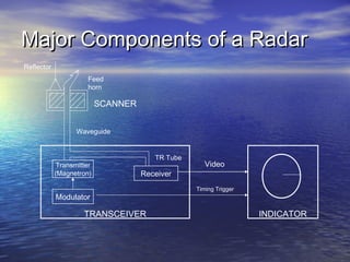
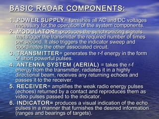
Introduction to Radar, Radar classification, The simple form of the Radar equation, Radar block diagram and operation, The Doppler Effect, Simple CW Radar Block Diagram, Block diagram of CW doppler radar with nonzero IF receiver, Applications of CW radar, Block Diagram of Frequency Modulated CW Radar
radar range equation
Working Processes Of Radar
History – Before Radar
Principle Of Operation
Radio Detection And Ranging
Radar Functions
Radar Bands And Usage
Terminology Of Radar Systems
Radar Range Equation
Types Of Radar
Pulse RADAR
Duplexer Using Pin Switches
Doppler Effect
Principle Of Continuous Wave Radar
Principles Of MTI RADAR
Different Types Of RADAR & It’s Applications
Industrial Training at Shahjalal Fertilizer Company Limited (SFCL)MdTanvirMahtab2
This presentation is about the working procedure of Shahjalal Fertilizer Company Limited (SFCL). A Govt. owned Company of Bangladesh Chemical Industries Corporation under Ministry of Industries.
Hybrid optimization of pumped hydro system and solar- Engr. Abdul-Azeez.pdffxintegritypublishin
Advancements in technology unveil a myriad of electrical and electronic breakthroughs geared towards efficiently harnessing limited resources to meet human energy demands. The optimization of hybrid solar PV panels and pumped hydro energy supply systems plays a pivotal role in utilizing natural resources effectively. This initiative not only benefits humanity but also fosters environmental sustainability. The study investigated the design optimization of these hybrid systems, focusing on understanding solar radiation patterns, identifying geographical influences on solar radiation, formulating a mathematical model for system optimization, and determining the optimal configuration of PV panels and pumped hydro storage. Through a comparative analysis approach and eight weeks of data collection, the study addressed key research questions related to solar radiation patterns and optimal system design. The findings highlighted regions with heightened solar radiation levels, showcasing substantial potential for power generation and emphasizing the system's efficiency. Optimizing system design significantly boosted power generation, promoted renewable energy utilization, and enhanced energy storage capacity. The study underscored the benefits of optimizing hybrid solar PV panels and pumped hydro energy supply systems for sustainable energy usage. Optimizing the design of solar PV panels and pumped hydro energy supply systems as examined across diverse climatic conditions in a developing country, not only enhances power generation but also improves the integration of renewable energy sources and boosts energy storage capacities, particularly beneficial for less economically prosperous regions. Additionally, the study provides valuable insights for advancing energy research in economically viable areas. Recommendations included conducting site-specific assessments, utilizing advanced modeling tools, implementing regular maintenance protocols, and enhancing communication among system components.
Explore the innovative world of trenchless pipe repair with our comprehensive guide, "The Benefits and Techniques of Trenchless Pipe Repair." This document delves into the modern methods of repairing underground pipes without the need for extensive excavation, highlighting the numerous advantages and the latest techniques used in the industry.
Learn about the cost savings, reduced environmental impact, and minimal disruption associated with trenchless technology. Discover detailed explanations of popular techniques such as pipe bursting, cured-in-place pipe (CIPP) lining, and directional drilling. Understand how these methods can be applied to various types of infrastructure, from residential plumbing to large-scale municipal systems.
Ideal for homeowners, contractors, engineers, and anyone interested in modern plumbing solutions, this guide provides valuable insights into why trenchless pipe repair is becoming the preferred choice for pipe rehabilitation. Stay informed about the latest advancements and best practices in the field.
Welcome to WIPAC Monthly the magazine brought to you by the LinkedIn Group Water Industry Process Automation & Control.
In this month's edition, along with this month's industry news to celebrate the 13 years since the group was created we have articles including
A case study of the used of Advanced Process Control at the Wastewater Treatment works at Lleida in Spain
A look back on an article on smart wastewater networks in order to see how the industry has measured up in the interim around the adoption of Digital Transformation in the Water Industry.
NO1 Uk best vashikaran specialist in delhi vashikaran baba near me online vas...Amil Baba Dawood bangali
Contact with Dawood Bhai Just call on +92322-6382012 and we'll help you. We'll solve all your problems within 12 to 24 hours and with 101% guarantee and with astrology systematic. If you want to take any personal or professional advice then also you can call us on +92322-6382012 , ONLINE LOVE PROBLEM & Other all types of Daily Life Problem's.Then CALL or WHATSAPP us on +92322-6382012 and Get all these problems solutions here by Amil Baba DAWOOD BANGALI
#vashikaranspecialist #astrologer #palmistry #amliyaat #taweez #manpasandshadi #horoscope #spiritual #lovelife #lovespell #marriagespell#aamilbabainpakistan #amilbabainkarachi #powerfullblackmagicspell #kalajadumantarspecialist #realamilbaba #AmilbabainPakistan #astrologerincanada #astrologerindubai #lovespellsmaster #kalajaduspecialist #lovespellsthatwork #aamilbabainlahore#blackmagicformarriage #aamilbaba #kalajadu #kalailam #taweez #wazifaexpert #jadumantar #vashikaranspecialist #astrologer #palmistry #amliyaat #taweez #manpasandshadi #horoscope #spiritual #lovelife #lovespell #marriagespell#aamilbabainpakistan #amilbabainkarachi #powerfullblackmagicspell #kalajadumantarspecialist #realamilbaba #AmilbabainPakistan #astrologerincanada #astrologerindubai #lovespellsmaster #kalajaduspecialist #lovespellsthatwork #aamilbabainlahore #blackmagicforlove #blackmagicformarriage #aamilbaba #kalajadu #kalailam #taweez #wazifaexpert #jadumantar #vashikaranspecialist #astrologer #palmistry #amliyaat #taweez #manpasandshadi #horoscope #spiritual #lovelife #lovespell #marriagespell#aamilbabainpakistan #amilbabainkarachi #powerfullblackmagicspell #kalajadumantarspecialist #realamilbaba #AmilbabainPakistan #astrologerincanada #astrologerindubai #lovespellsmaster #kalajaduspecialist #lovespellsthatwork #aamilbabainlahore #Amilbabainuk #amilbabainspain #amilbabaindubai #Amilbabainnorway #amilbabainkrachi #amilbabainlahore #amilbabaingujranwalan #amilbabainislamabad
Student information management system project report ii.pdfKamal Acharya
Our project explains about the student management. This project mainly explains the various actions related to student details. This project shows some ease in adding, editing and deleting the student details. It also provides a less time consuming process for viewing, adding, editing and deleting the marks of the students.
Final project report on grocery store management system..pdfKamal Acharya
In today’s fast-changing business environment, it’s extremely important to be able to respond to client needs in the most effective and timely manner. If your customers wish to see your business online and have instant access to your products or services.
Online Grocery Store is an e-commerce website, which retails various grocery products. This project allows viewing various products available enables registered users to purchase desired products instantly using Paytm, UPI payment processor (Instant Pay) and also can place order by using Cash on Delivery (Pay Later) option. This project provides an easy access to Administrators and Managers to view orders placed using Pay Later and Instant Pay options.
In order to develop an e-commerce website, a number of Technologies must be studied and understood. These include multi-tiered architecture, server and client-side scripting techniques, implementation technologies, programming language (such as PHP, HTML, CSS, JavaScript) and MySQL relational databases. This is a project with the objective to develop a basic website where a consumer is provided with a shopping cart website and also to know about the technologies used to develop such a website.
This document will discuss each of the underlying technologies to create and implement an e- commerce website.
2. LEARNING OBJECTIVES:LEARNING OBJECTIVES:
At the end of the lesson the student shall be able to…At the end of the lesson the student shall be able to…
1. Have sufficient knowledge of fundamentals and1. Have sufficient knowledge of fundamentals and
principles of radar.principles of radar.
2. Understand the factors that affects the reliability2. Understand the factors that affects the reliability
and performance of the radar.and performance of the radar.
3. • On Chapter V Regulation 19 of the SOLAS 1974On Chapter V Regulation 19 of the SOLAS 1974
Convention, it lays down the CarriageConvention, it lays down the Carriage
requirement for shipborne navigational systemsrequirement for shipborne navigational systems
and equipment. Under Regulation V/19and equipment. Under Regulation V/19
paragraph 2.7, 2.7.1, 2.7.2 it requires that allparagraph 2.7, 2.7.1, 2.7.2 it requires that all
ships of 3,000 gross tonnage and upwards shallships of 3,000 gross tonnage and upwards shall
have ahave a 3 GHz radar (10-cm or S-band)3 GHz radar (10-cm or S-band) or,or,
where considered appropriate by thewhere considered appropriate by the
administration, a secondadministration, a second 9GHz radar (3-cm or9GHz radar (3-cm or
X-band)X-band), or other means, to determine and, or other means, to determine and
display the range and bearing of other surfacedisplay the range and bearing of other surface
craft, obstructions, buoys, shorelines andcraft, obstructions, buoys, shorelines and
navigational marks to assist in navigation and innavigational marks to assist in navigation and in
collision avoidance.collision avoidance.
• Moreover the International for PreventingMoreover the International for Preventing
Collision at Sea 1972 requires the use of radar inCollision at Sea 1972 requires the use of radar in
the ship.the ship.
4. What is RADAR?What is RADAR?
RADAR- it is a term derived fromRADAR- it is a term derived from RadioRadio
Detection And RangingDetection And Ranging . It is applied to. It is applied to
electronic equipment designed to determineelectronic equipment designed to determine
distance by measuring the time required for adistance by measuring the time required for a
radio signal to travel from a transmitter to aradio signal to travel from a transmitter to a
target and return either as a reflected echo or astarget and return either as a reflected echo or as
a retransmitted signal from a transpondera retransmitted signal from a transponder
triggered by the original signal.triggered by the original signal.
5. BASIC PRINCIPLEBASIC PRINCIPLE
Radar performs the same kind of action,Radar performs the same kind of action,
it produces extremely short burst of radioit produces extremely short burst of radio
signal. Short radio waves like acoustic wavessignal. Short radio waves like acoustic waves
are reflected by objects that comes in theirare reflected by objects that comes in their
way.way.
6. On board a ship the radar has two main tasks:On board a ship the radar has two main tasks:
1.1. To function as an aid to prevent collisions, asTo function as an aid to prevent collisions, as
with the help of radar, one can “see” in fog andwith the help of radar, one can “see” in fog and
darkness.darkness.
2.2. To assist in the navigation, particularly atTo assist in the navigation, particularly at
landfalls and when navigating in coastal waterslandfalls and when navigating in coastal waters
or in archipelagos.or in archipelagos.
7. RADIO WAVE TERMINOLOGYRADIO WAVE TERMINOLOGY
• CrestCrest – the highest point on wave curve ( in the– the highest point on wave curve ( in the
direction considered positive )direction considered positive )
• TroughTrough – the lowest point on wave curve ( in the– the lowest point on wave curve ( in the
direction considered negative )direction considered negative )
• PeakPeak - either point on wave curve i.e. the crest- either point on wave curve i.e. the crest
or troughor trough
• AmplitudeAmplitude – the maximum displacement of the– the maximum displacement of the
wave from its mean or zero valuewave from its mean or zero value
• Wave FrontWave Front – the forward side of any wave– the forward side of any wave
8. • CycleCycle – one complete oscillation or one complete– one complete oscillation or one complete
wave, i.e. that part of the wave motion passing zerowave, i.e. that part of the wave motion passing zero
in one direction until it passes the next zero in thein one direction until it passes the next zero in the
same direction. This is also that part of the wavesame direction. This is also that part of the wave
motion from crest to crest or from trough to troughmotion from crest to crest or from trough to trough
• Wave LengthWave Length – the distance along the direction of– the distance along the direction of
propagation between successive crests or troughs.propagation between successive crests or troughs.
When one cycle has been completed, the wave hasWhen one cycle has been completed, the wave has
travelled one wavelength ( it is usually expressed intravelled one wavelength ( it is usually expressed in
metric units – meters, centimeters, etc.)metric units – meters, centimeters, etc.)
• FrequencyFrequency – the number of cycles completed per– the number of cycles completed per
secondsecond
9. This is given inThis is given in hertz (Hz)hertz (Hz), a unit of measure of, a unit of measure of
frequency.frequency. 1 Hz1 Hz simply meanssimply means 1 cycle per1 cycle per
secondsecond..
DIFFERENT FREQUENCIES:DIFFERENT FREQUENCIES:
• KilohertzKilohertz (kHz) – 1000 cycles per second(kHz) – 1000 cycles per second
• MegahertzMegahertz (MHz) – 1,000,000 cycles per second(MHz) – 1,000,000 cycles per second
• GigahertzGigahertz (GHz) – 1,000,000,000 cycles per(GHz) – 1,000,000,000 cycles per
secondsecond
• TerahertzTerahertz (THz) – 1,000,000,000,000 cycles per(THz) – 1,000,000,000,000 cycles per
secondsecond
10. • PetahertzPetahertz (PHz) – 1,000,000,000,000,000(PHz) – 1,000,000,000,000,000
cycles per secondcycles per second
• ExahertzExahertz (EHz) – 1,000,000,000,000,000,000(EHz) – 1,000,000,000,000,000,000
cycles per secondcycles per second
Did you know?Did you know?
““HertzHertz” is named after the German physicist” is named after the German physicist
Heinrich HertzHeinrich Hertz
11. 3 MAJOR COMPONENTS OF RADAR3 MAJOR COMPONENTS OF RADAR
1) SCANNER-1) SCANNER- consists of the reflector, the driveconsists of the reflector, the drive
assembly, and horns which rotate betweenassembly, and horns which rotate between 1010
and 20 rpmand 20 rpm depending on the design of thedepending on the design of the
equipment.equipment.
• RADAR ENERGY is conducted to the horn fromRADAR ENERGY is conducted to the horn from
the transmitter through a hollow rectangular pipethe transmitter through a hollow rectangular pipe
calledcalled WAVEGUIDEWAVEGUIDE. At the end of the horn is. At the end of the horn is
a plastic window through which energy passesa plastic window through which energy passes
and is directed into the reflector.and is directed into the reflector.
• The reflector in turn focuses the energy into aThe reflector in turn focuses the energy into a
narrow beam which is being constantly rotated.narrow beam which is being constantly rotated.
12. 2) TRANSCEIVER2) TRANSCEIVER
• On the diagram, the transmitter and receiver areOn the diagram, the transmitter and receiver are
interconnected with the scanner through ainterconnected with the scanner through a
common hollow pipe called waveguide.common hollow pipe called waveguide.
• In transmitting, the magnetron tube provides theIn transmitting, the magnetron tube provides the
radio wave’s energy to the scanner.radio wave’s energy to the scanner.
• The magnetron will extinguish after a short burstThe magnetron will extinguish after a short burst
of energy. Radar waves travel atof energy. Radar waves travel at 328 yards328 yards
per microsecondper microsecond . The modulator provides the. The modulator provides the
timing of the transmitted pulses which are senttiming of the transmitted pulses which are sent
out by the magnetron.out by the magnetron.
13. 3) INDICATOR3) INDICATOR
• It provides the radar observer with theIt provides the radar observer with the
information he seeks in collisioninformation he seeks in collision
avoidance and navigationavoidance and navigation
• CATHODE RAY TUBE- it is on this scopeCATHODE RAY TUBE- it is on this scope
that all objects which reflect radar energythat all objects which reflect radar energy
are seen.are seen.
• The center represents own shipThe center represents own ship
• SWEEP LINE - The sweep isSWEEP LINE - The sweep is
synchronized (trigger) with the number ofsynchronized (trigger) with the number of
pulses being transmitted.pulses being transmitted.
14. Major Components of a RadarMajor Components of a Radar
INDICATORTRANSCEIVER
Receiver
Transmitter
(Magnetron)
Modulator
Video
Timing Trigger
TR Tube
Feed
horn
SCANNER
Waveguide
Reflector
15. BASIC RADAR COMPONENTS:BASIC RADAR COMPONENTS:
1. POWER SUPPLY1. POWER SUPPLY = furnishes all AC and DC voltages= furnishes all AC and DC voltages
necessary for the operation of the system components.necessary for the operation of the system components.
2. MODULATOR=2. MODULATOR= produces the synchronizing signalsproduces the synchronizing signals
that trigger the transmitter the required number of timesthat trigger the transmitter the required number of times
per second. It also triggers the indicator sweep andper second. It also triggers the indicator sweep and
coordinates the other associated circuit.coordinates the other associated circuit.
3. TRANSMITTER3. TRANSMITTER= generates the r-f energy in the form= generates the r-f energy in the form
of short powerful pulses.of short powerful pulses.
4. ANTENNA SYSTEM (AERIAL)4. ANTENNA SYSTEM (AERIAL) = takes the r-f= takes the r-f
energy from the transmitter, radiates it in a highlyenergy from the transmitter, radiates it in a highly
directional beam, receives any returning echoes anddirectional beam, receives any returning echoes and
passes it to the receiver.passes it to the receiver.
5. RECEIVER5. RECEIVER= amplifies the weak radio energy pulses= amplifies the weak radio energy pulses
(echoes) returned by a contact and reproduces them as(echoes) returned by a contact and reproduces them as
video pulses passed to the indicator.video pulses passed to the indicator.
6. INDICATOR=6. INDICATOR= produces a visual indication of the echoproduces a visual indication of the echo
pulses in a manner that furnishes the desired informationpulses in a manner that furnishes the desired information
(ranges and bearings of targets).(ranges and bearings of targets).
16. Operational limitationsOperational limitations
1. It is a complex electronic instrument,1. It is a complex electronic instrument,
dependent upon power source, and isdependent upon power source, and is
subject to mechanical and electricalsubject to mechanical and electrical
failure.failure.
2. There is a minimum range limitation,2. There is a minimum range limitation,
resulting from returning echoes fromresulting from returning echoes from
nearby wave crest (sea return), and anearby wave crest (sea return), and a
maximum range limitation.maximum range limitation.
3. Interpretation of the radarscope display3. Interpretation of the radarscope display
is difficult at times, even for a trainedis difficult at times, even for a trained
and experience operator.and experience operator.
17. 4. Line of Position (LOP) from radar4. Line of Position (LOP) from radar
bearings is inaccurate. Care must bebearings is inaccurate. Care must be
taken especially when using land mark,taken especially when using land mark,
to be certain of which features are beingto be certain of which features are being
painted on the radar set. The operatorspainted on the radar set. The operators
must be constantly aware of the pitfallsmust be constantly aware of the pitfalls
associated with radar range resolutionassociated with radar range resolution
and radar shadow zones.and radar shadow zones.
5. Radar is susceptible to both natural and5. Radar is susceptible to both natural and
deliberate interference.deliberate interference.
6. Radar shadows and sea return may6. Radar shadows and sea return may
render objects undetectable by radar.render objects undetectable by radar.
18. RADAR operating controls
1. Indicator power switch
This switch on the indicator has OFF, STAND-BY,
and OPERATE (ON) positions. If the switch is turned
directly from the OFF to OPERATE positions, there is a
warm up period of about 3 minutes before the radar set
is in full operation. During the warm up period the
cathodes of the tubes are heated, this heating being
necessary prior to applying high voltages. If the switch is
in the STANDBY position for a period longer than that
required warm up, the radar set is placed in full operation
immediately upon turning the switch to the operate
position. Keeping the radar set in Standby when not in
use tends to lessen maintenance problems. Frequent
switching from OFF to OPERATE tends to cause tube
failures
19. 2. Brilliance Control
It is adjusted to make the trace of the rotating
sweep visible but not too bright.
3. Receiver Gain Control
The receiver gain control is adjusted until a
speckled background just appears on the PPI.
With too little gain, weak echoes may not be
detected; with excessive gain, strong echoes
may not be detected because of the poor
contrast between echoes and the background of
the PPI display. On shifting to a different range
scale, the brightness may change. Generally,
the required readjustment may be affected
through use of the receiver gain control alone
although the brightness of the PPI display is
dependent upon the settings of the receiver gain
and brilliance controls.
20. 4. Rain Clutter Control
It provides the means for breaking up clutter
which otherwise could obscure the echo of a
target of interest.
5. Sea Clutter Control
This control is used with a circuit which is
designed to suppress sea clutter out to a limited
distance from the ship. Its purpose is to enable
the detection of close contact which otherwise
might be obscured by sea clutter. This control
must be used judiciously in conjunction with the
receiver gain control.
21. 6. Tuning Control
If the radar set design does not have an
automatic frequency control (AFC) circuit to
keep the receiver tuned to the transmitter for
optimum performance, the manual tuning control
must be adjusted to obtain the best reception of
echoes. Some radar set designs having
automatic frequency control also have
provisions for manual tuning in case of failure of
the AFC. Without automatic frequency control
the tuning must be adjusted at frequent intervals
after the set is turned on. After 30minutes
operation, this frequent adjustment is not
required normally. The tuning should be checked
periodically to ensure that the radar is operating
properly, particularly if no contacts are being
observed.
22. 7. Electronic Bearing Line (EBL)
The brightness of electronic bearing cursor is
adjusted by a control for this purpose. Unless
the electronic bearing cursor appears as a
dashed or dotted line, the brightness levels of
the electronic bearing cursor and the heading
flash should be different to serve as an aid to
their identification.
8. Variable Range Marker (VRM)
The brightness of the variable range marker
is adjusted by the control labeled VRM. This
control is adjusted so that the ring described by
the VRM is sharp and clear but not too bright.
In conclusion, although radar is not a panacea for
the navigator, intelligent use of its capabilities certainly
will aid in safely directing the movements of a vessel.
23. CHARACTERISTICS OF RADAR SETCHARACTERISTICS OF RADAR SET
AND FACTORS AFFECTINGAND FACTORS AFFECTING
PERFORMANCE ACCURACY:PERFORMANCE ACCURACY:
1. CARRIER FREQUENCY=1. CARRIER FREQUENCY= the frequency atthe frequency at
which the r-f energy is generated.which the r-f energy is generated.
TWO TYPES:TWO TYPES:
1.1. High Frequency RadarHigh Frequency Radar (3 CM.,X-BAND,(3 CM.,X-BAND,
10,000Mhz) – good for bad weather.10,000Mhz) – good for bad weather.
Long range detection (used for landfall)Long range detection (used for landfall)
2.2. Low Frequency RadarLow Frequency Radar (10 CM.,S-BAND,(10 CM.,S-BAND,
3,000Mhz) – good for all types of3,000Mhz) – good for all types of
weather. Short range detectionweather. Short range detection
(entering and transiting channels)(entering and transiting channels)
24. 2. PULSE REPETITION RATE (PRR) =2. PULSE REPETITION RATE (PRR) = thethe
number of pulses transmitted per secondnumber of pulses transmitted per second
3. PULSE LENGTH=3. PULSE LENGTH= the transmission time of athe transmission time of a
single pulse of radio-frequency (r-f) energysingle pulse of radio-frequency (r-f) energy
measured in microseconds.measured in microseconds.
a. Short Pulse (SP) – uses range scale of 6a. Short Pulse (SP) – uses range scale of 6
milesmiles
and below.and below.
b. Medium Pulse (MP) – uses range scale of 6b. Medium Pulse (MP) – uses range scale of 6
miles to 12 miles.miles to 12 miles.
c. Long Pulse (LP) – uses range scale of 12c. Long Pulse (LP) – uses range scale of 12
milesmiles
and above.and above.
4. POWER RELATIONSHIP -=4. POWER RELATIONSHIP -= the powerthe power
level of each pulse of radiated energy.level of each pulse of radiated energy.
25. FACTORS AFFECTING BEARING ANDFACTORS AFFECTING BEARING AND
RANGE ACCURACYRANGE ACCURACY
1.1. In order to achieve the required directionalIn order to achieve the required directional
characteristic the horizontal beam width limitscharacteristic the horizontal beam width limits
must be narrow.must be narrow. HORIZONTAL BEAMHORIZONTAL BEAM
WIDTH -WIDTH - the angle within which the energy isthe angle within which the energy is
constrainedconstrained
2.2. Incorrect positioningIncorrect positioning of a contact inside theof a contact inside the
scanner housing or pedestal when the radarscanner housing or pedestal when the radar
was installed.was installed.
3.3. Failure to center the origin of the trace will resultFailure to center the origin of the trace will result
in error in bearing which are obtained.in error in bearing which are obtained.
26. Range DiscriminationRange Discrimination – also referred as– also referred as
range resolution, described the ability ofrange resolution, described the ability of
the radar system to display separately thethe radar system to display separately the
echoes of two targets which lie on theechoes of two targets which lie on the
same bearing but which are closelysame bearing but which are closely
spaced in range.spaced in range.
Bearing DiscriminationBearing Discrimination – also referred– also referred
as bearing resolution, described the abilityas bearing resolution, described the ability
of the radar system to display separatelyof the radar system to display separately
the echoes of two targets, which lie at thethe echoes of two targets, which lie at the
same range but are closely spaced insame range but are closely spaced in
bearing.bearing.
27. EXTERNAL FACTORS AFFECTINGEXTERNAL FACTORS AFFECTING
RADAR DETECTIONRADAR DETECTION
1.1. Line of SightLine of Sight – this means the even though the– this means the even though the
radar is delivering powerful pulse and the targetradar is delivering powerful pulse and the target
is capable, the target will not be detected if it isis capable, the target will not be detected if it is
below the radar horizon.below the radar horizon.
2.2. RefractionRefraction – takes place when the velocity of a– takes place when the velocity of a
wave is changed. This can happen when thewave is changed. This can happen when the
wave front passes the boundary of twowave front passes the boundary of two
substances of different densities. If the changesubstances of different densities. If the change
of density is increasing or decreasing gradually,of density is increasing or decreasing gradually,
the direction of the wave front gradually changethe direction of the wave front gradually change
and will follow a curve path.and will follow a curve path.
28. There are two classes of abnormal refraction, whichThere are two classes of abnormal refraction, which
caused abnormal radar “visibility”.caused abnormal radar “visibility”.
a)a) Super-RefractionSuper-Refraction – Occurs when the rate of– Occurs when the rate of
decrease in refractive index with height is greaterdecrease in refractive index with height is greater
than standard condition, the radar beam tends tothan standard condition, the radar beam tends to
bend down slightly more and so targets may bebend down slightly more and so targets may be
detected at ranges which are slightly greater thandetected at ranges which are slightly greater than
standard.standard.
b.b. Sub-RefractionSub-Refraction – occurs when the refractive– occurs when the refractive
index of the atmosphere decreases less rapidlyindex of the atmosphere decreases less rapidly
with height than under standard conditions. As awith height than under standard conditions. As a
result the radar beam is bent downward slightlyresult the radar beam is bent downward slightly
less than standard conditions. This means thatless than standard conditions. This means that
the target will be detected at a slightly reducedthe target will be detected at a slightly reduced
range.range.
29. 3.3. PrecipitationPrecipitation – is the general term used to– is the general term used to
describe collectively various states in which waterdescribe collectively various states in which water
can manifest itself in the atmosphere, of which rain,can manifest itself in the atmosphere, of which rain,
fog, snow and hails are examples. Reflections fromfog, snow and hails are examples. Reflections from
precipitation can produce unwanted echoes on theprecipitation can produce unwanted echoes on the
screen and these are referred to as rain clutterscreen and these are referred to as rain clutter
though it is recognized that they may originate fromthough it is recognized that they may originate from
other forms of precipitation.other forms of precipitation.
4.4. Blind Spots and Shadow AreasBlind Spots and Shadow Areas – are caused– are caused
byby obstructionobstruction on land, by other vessel or byon land, by other vessel or by
obstruction of own ship in the path of radar beam. Inobstruction of own ship in the path of radar beam. In
a blind area the radar beam is completely cut-off. Ina blind area the radar beam is completely cut-off. In
a shadow area of reduced intensity when the beamsa shadow area of reduced intensity when the beams
bends or diffracts round ridges or smaller objects.bends or diffracts round ridges or smaller objects.
30. CAUSED AND EFFECT OF MULTIPLECAUSED AND EFFECT OF MULTIPLE
ECHOESECHOES
Multiple echoes are caused by the reflectionMultiple echoes are caused by the reflection
between own ship and the target before thebetween own ship and the target before the
scanner finally collects its energy. The effect on thescanner finally collects its energy. The effect on the
screen is that, besides the original echo, there arescreen is that, besides the original echo, there are
seen, on the same line of bearing, one or moreseen, on the same line of bearing, one or more
echoes, equidistantly spaced and having ranges ofechoes, equidistantly spaced and having ranges of
multiple of the true range.multiple of the true range.
Multiple echoes are nuisance when a ship isMultiple echoes are nuisance when a ship is
approaching an anchor roads where several shipsapproaching an anchor roads where several ships
are riding at anchor. The picture on the screen canare riding at anchor. The picture on the screen can
become confused due to several multiple echoesbecome confused due to several multiple echoes
of different ships, and it is difficult to distinguishof different ships, and it is difficult to distinguish
between true and false echoes.between true and false echoes.
31. DIFFERENT TYPES OF DISPLAY MODEDIFFERENT TYPES OF DISPLAY MODE
1.1. True Motion (TM)True Motion (TM) – in as true motion– in as true motion
presentation, the echo movement of all targets ispresentation, the echo movement of all targets is
rendered independent of the moving vessel.rendered independent of the moving vessel.
2.2. Relative Motion (RMRelative Motion (RM ) – in the relative motion) – in the relative motion
presentation, the origin of display is stationary andpresentation, the origin of display is stationary and
the movement of all targets is shown with respect tothe movement of all targets is shown with respect to
the observing vessel.the observing vessel.
3.3. Ship’s-Head-Up Orientation (HU)Ship’s-Head-Up Orientation (HU) – the– the
observer views the picture with the heading markerobserver views the picture with the heading marker
at the “top” of the screen.at the “top” of the screen.
32. DIFFERENT TYPES OF DISPLAYDIFFERENT TYPES OF DISPLAY
MODEMODE
4.4. North-Up Orientation (NU)North-Up Orientation (NU) – the heading– the heading
marker is aligned with the graduation on themarker is aligned with the graduation on the
fixed bearing scale, which correspond with thefixed bearing scale, which correspond with the
instantaneous value of the ship’s heading, As ainstantaneous value of the ship’s heading, As a
result, the 000result, the 00000
graduation represents true north.graduation represents true north.
Thus, the observer views the picture with northThus, the observer views the picture with north
at the “top” of the screen.at the “top” of the screen.
5.5. Course-Up Orientation (CU) StabilizedCourse-Up Orientation (CU) Stabilized ––
the heading marker is aligned to the graduationthe heading marker is aligned to the graduation
on the fixed bearing scale at an instant theon the fixed bearing scale at an instant the
vessel is right on the chosen course.vessel is right on the chosen course.
33. RADAR SCOPE INTERPRETATIONRADAR SCOPE INTERPRETATION
PIP CHARACTERISTICSPIP CHARACTERISTICS
1. Size of PIP – depends on the following:1. Size of PIP – depends on the following:
a. Range of targeta. Range of target
b. Size of targetb. Size of target
c. Height of targetc. Height of target
d. Aspect of target: bow or broadsided. Aspect of target: bow or broadside
e. Material composition of targete. Material composition of target
f. Correctness of tuningf. Correctness of tuning
2. Shape of PIP – depends on the type of target2. Shape of PIP – depends on the type of target
and contour.and contour.
3. Movement or change in ranges and bearings.3. Movement or change in ranges and bearings.
34. TARGET CHARACTERISTICSTARGET CHARACTERISTICS
1. Land Targets1. Land Targets
a. Covers a greater area on the screen thana. Covers a greater area on the screen than
other targets.other targets.
b. No motion with TRUE MOTION radar.b. No motion with TRUE MOTION radar.
c. With RELATIVE MOTION radar, movement isc. With RELATIVE MOTION radar, movement is
opposite and equal to the motion of the ship.opposite and equal to the motion of the ship.
d. In the geographic plot, it should be at its expectedd. In the geographic plot, it should be at its expected
position.position.
2. Ship Target2. Ship Target
a. At medium range it is bright.a. At medium range it is bright.
b. Steady and clearly defined image in the PPI.b. Steady and clearly defined image in the PPI.
c. PIP fades only when range becomes too great.c. PIP fades only when range becomes too great.
d. Small craft of fishing vessel appear at about 4 to 5 NM,d. Small craft of fishing vessel appear at about 4 to 5 NM,
as extremely weak echo.as extremely weak echo.
35. 3. Aircraft Targets3. Aircraft Targets
a. Rapid motion of the echo on the radar scope.a. Rapid motion of the echo on the radar scope.
b. Echo fades and appears again shortly.b. Echo fades and appears again shortly.
c. It brightens and the rapidly decrease inc. It brightens and the rapidly decrease in
brightness.brightness.
4. Ice Detection4. Ice Detection
a. Iceberg – maybe detected in 15 to 20a. Iceberg – maybe detected in 15 to 20
n.miles.n.miles.
b. Bergy bits – part of ice berg that was chip off.b. Bergy bits – part of ice berg that was chip off.
Rises 15 feet above sea surface, echoes areRises 15 feet above sea surface, echoes are
weak and may be lost in the sea clutter.weak and may be lost in the sea clutter.
c. Growler – most dangerous ice formation.c. Growler – most dangerous ice formation.
Rises 6 feet above sea surface, extremelyRises 6 feet above sea surface, extremely
poor radar target because it is round due topoor radar target because it is round due to
wave action.wave action.
36. RADAR AS AN AID TO NAVIGATIONRADAR AS AN AID TO NAVIGATION
1. Advantage of Radar in Navigation1. Advantage of Radar in Navigation
a. Radar can be used when no other methods isa. Radar can be used when no other methods is
available.available.
b. Use at night or during condition of low visibility.b. Use at night or during condition of low visibility.
c. Provide accurate range information.c. Provide accurate range information.
d. Helpful anti-collision device.d. Helpful anti-collision device.
e. Track and locate squals and nearby tropicale. Track and locate squals and nearby tropical
storms.storms.
2. Limitation (Disadvantages)2. Limitation (Disadvantages)
a. Sometimes less accurate fix than by visual meansa. Sometimes less accurate fix than by visual means
b. Minimum range affected by the pulse width of theb. Minimum range affected by the pulse width of the
radar.radar.
c. Radars are subject to electronic failure.c. Radars are subject to electronic failure.
37. 3. Procedures and Techniques3. Procedures and Techniques
a. Radar fixesa. Radar fixes
b. Look-out informationb. Look-out information
c. Set and Driftc. Set and Drift
4. Methods of obtaining radar fixes4. Methods of obtaining radar fixes
a. Range and bearing to a single object, commonlya. Range and bearing to a single object, commonly
used when piloting close to shore.used when piloting close to shore.
b. Two or more bearings (cross bearing), the sameb. Two or more bearings (cross bearing), the same
method used by the navigator when takingmethod used by the navigator when taking
visual gyro bearings.visual gyro bearings.
c. Two or more ranges, the most accurate methodc. Two or more ranges, the most accurate method
especially when augmented by a visual gyroespecially when augmented by a visual gyro
bearings.bearings.
38. 5. Radar Aids Navigation5. Radar Aids Navigation
a.a. RACON (Radar Control)RACON (Radar Control) – a responder type– a responder type
beacons which is triggered by a pulse from a ship’sbeacons which is triggered by a pulse from a ship’s
radar. Sends out video signals (characteristics / I.D.)radar. Sends out video signals (characteristics / I.D.)
when the radar pulses strike the antenna receiver.when the radar pulses strike the antenna receiver.
b.b. RAMARK (Radar Marker)RAMARK (Radar Marker) – is a radar beacon– is a radar beacon
which transmit on all radar frequencies continuouslywhich transmit on all radar frequencies continuously
or at intervals, therefore your radar set will receiveor at intervals, therefore your radar set will receive
signals during the time your scanner is pointing tosignals during the time your scanner is pointing to
the direction of the beacon.the direction of the beacon.
c.c. TransponderTransponder – provides positive identification and– provides positive identification and
other relevant data.other relevant data.
39. PROCEDURES FOR ENSURING RANGEPROCEDURES FOR ENSURING RANGE
ACCURACYACCURACY
• Adjust the brilliance of the VRM, or EBL to obtainAdjust the brilliance of the VRM, or EBL to obtain
the finest possible line.the finest possible line.
• Measured the range to the nearest edge of theMeasured the range to the nearest edge of the
display echo.display echo.
• Use the rings when the target is on or close to aUse the rings when the target is on or close to a
ring.ring.
• Use VRM, EBL or joystick marker to interpolateUse VRM, EBL or joystick marker to interpolate
between the rings.between the rings.
• Regularly check VRM, EBL or joystick markerRegularly check VRM, EBL or joystick marker
against the ring.against the ring.
40. PROCEDURES FOR ENSURING BEARINGPROCEDURES FOR ENSURING BEARING
ACCURACYACCURACY
• Check regularly that the heading markerCheck regularly that the heading marker
accurately represents the ship’s fore and aft line.accurately represents the ship’s fore and aft line.
• Ensure that the picture is correctly orientated.Ensure that the picture is correctly orientated.
• Use an appropriate range scale with the targetUse an appropriate range scale with the target
as near to the edge of the screen as possible.as near to the edge of the screen as possible.
• Check the EBL or joystick marker by super-Check the EBL or joystick marker by super-
imposing them on the heading marker at whichimposing them on the heading marker at which
the bearing and the heading should agree.the bearing and the heading should agree.
• Any error should be noted, applied to bearingAny error should be noted, applied to bearing
and caused investigated.and caused investigated.
• For small isolated target align the cursor, EBL orFor small isolated target align the cursor, EBL or
marker with the center of the target.marker with the center of the target.