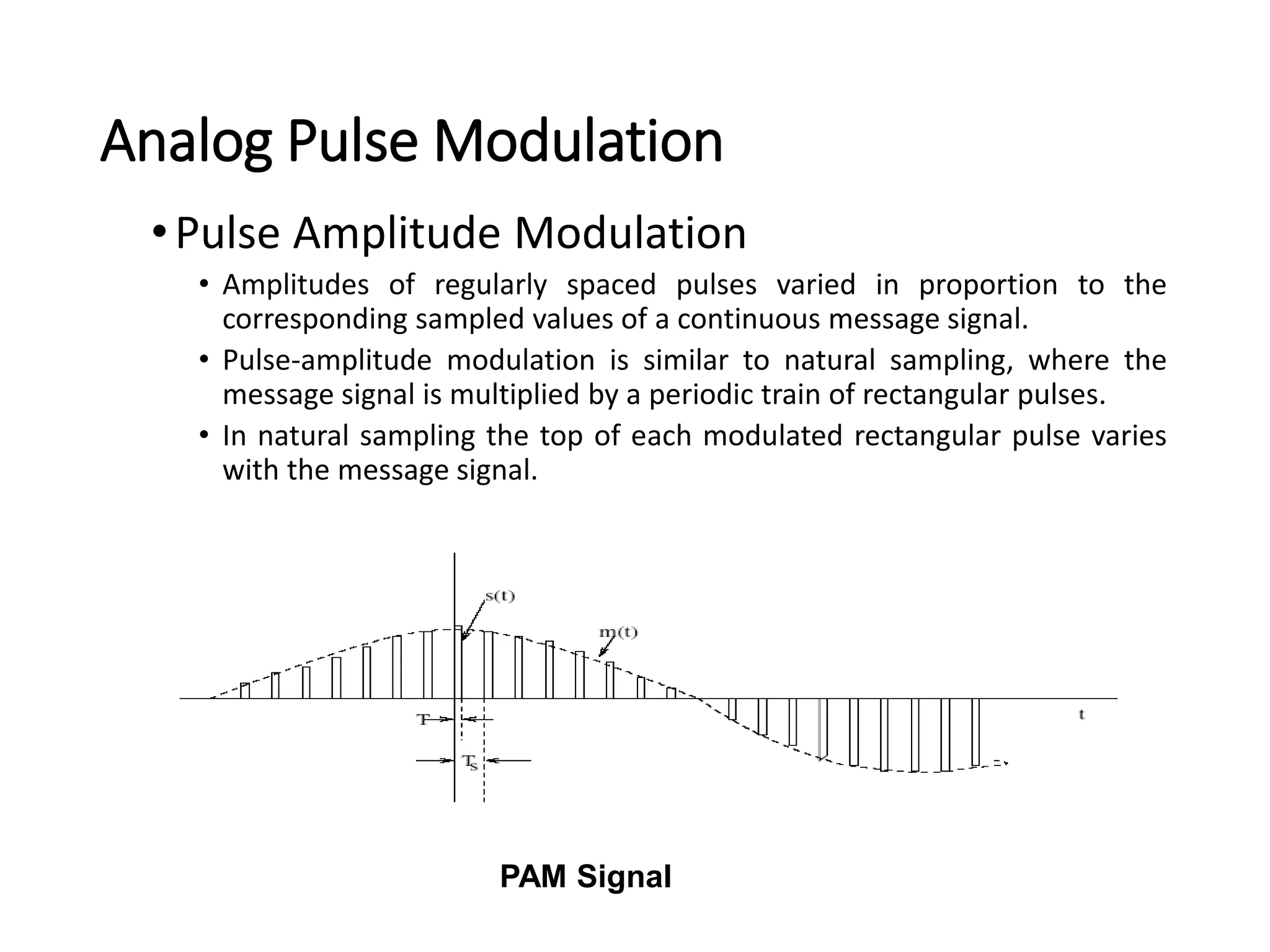
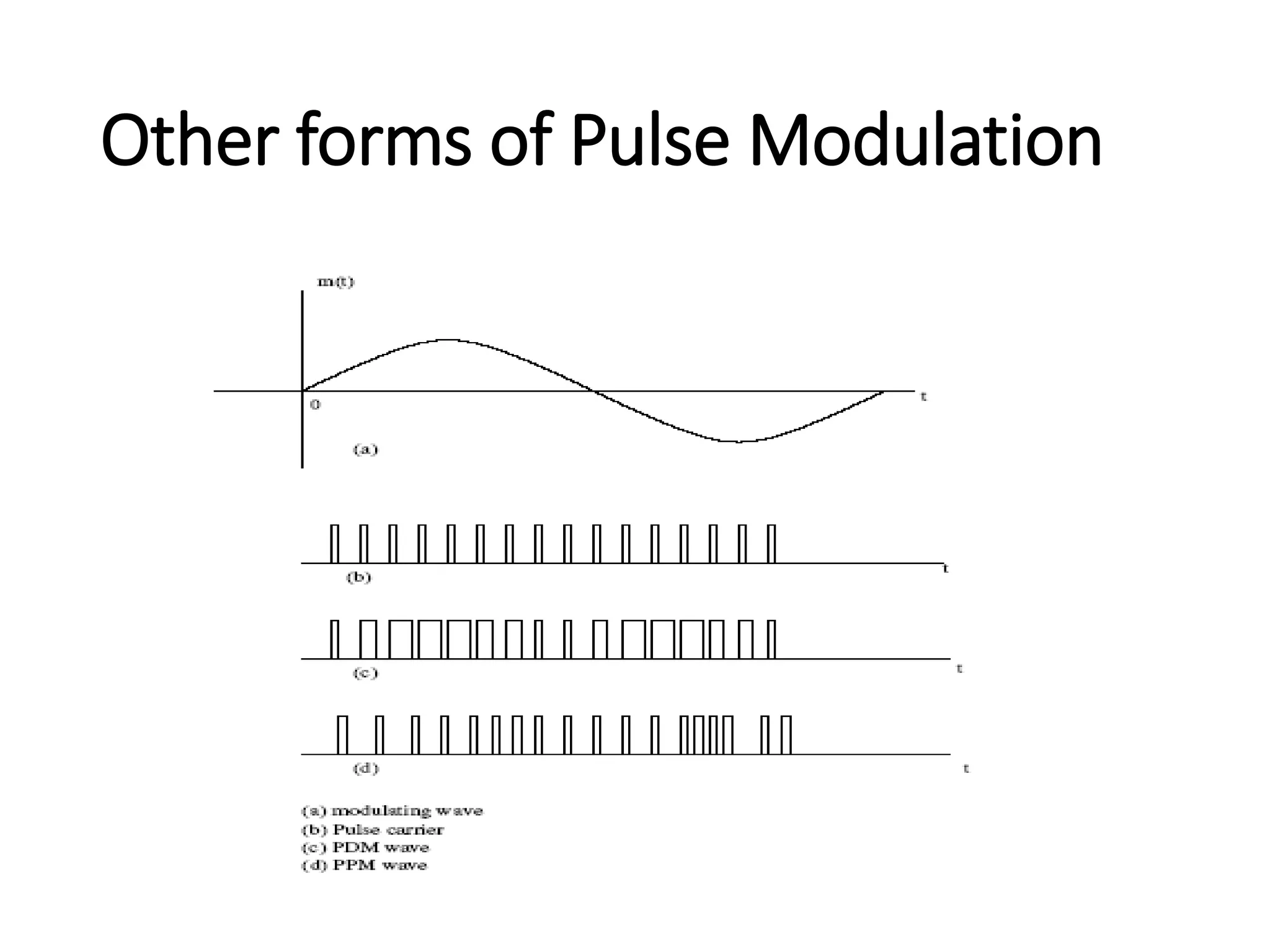
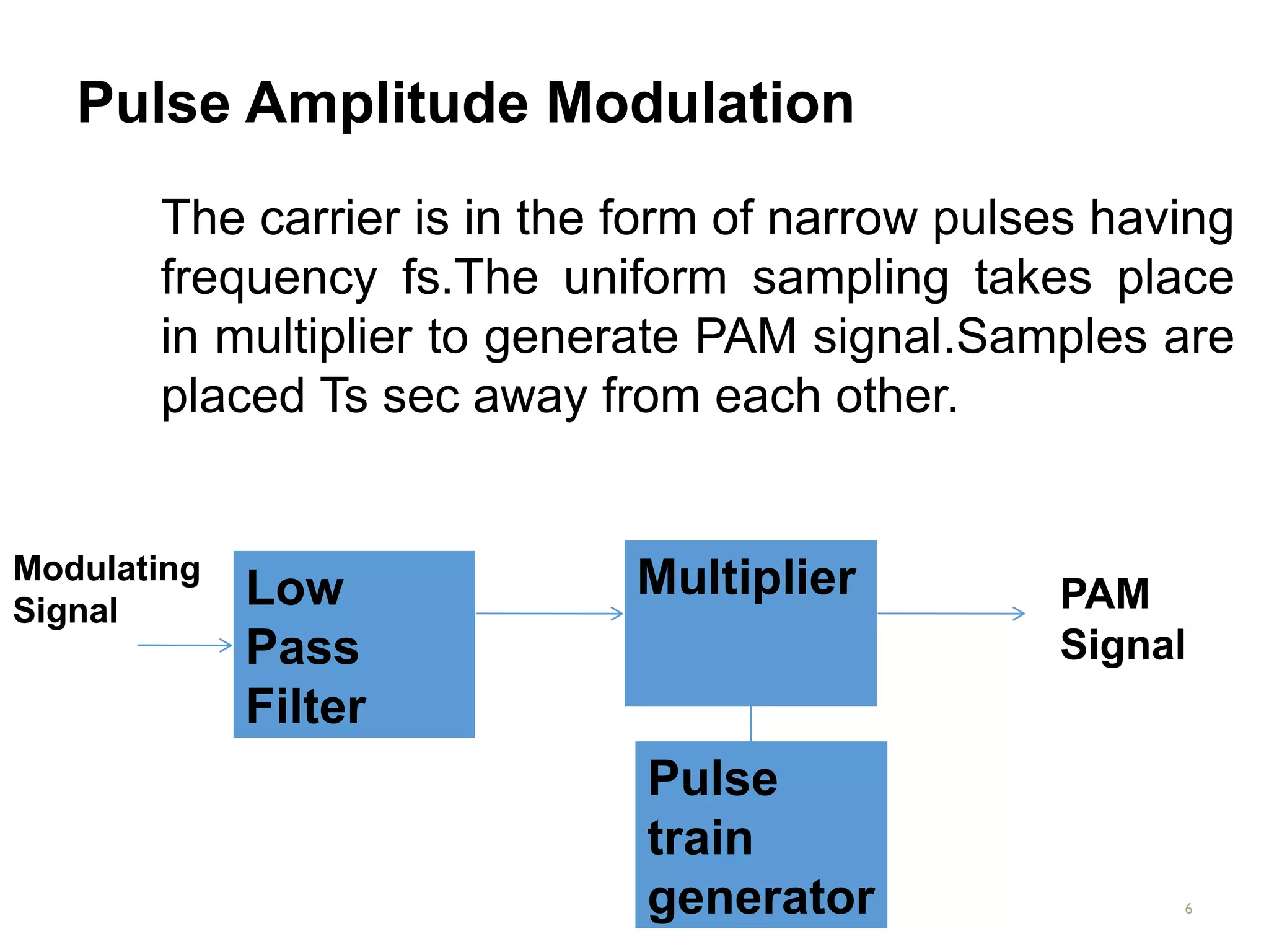
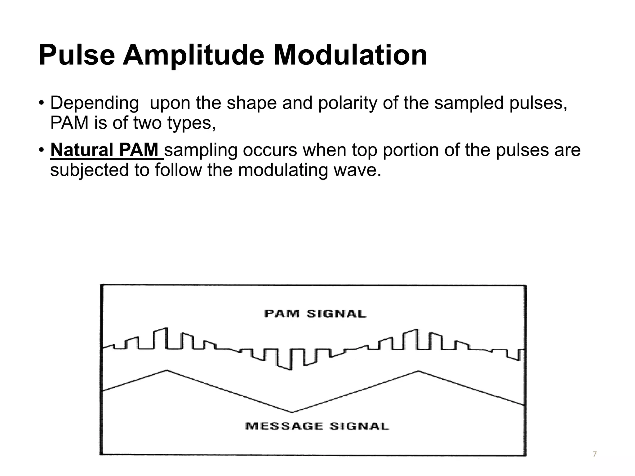
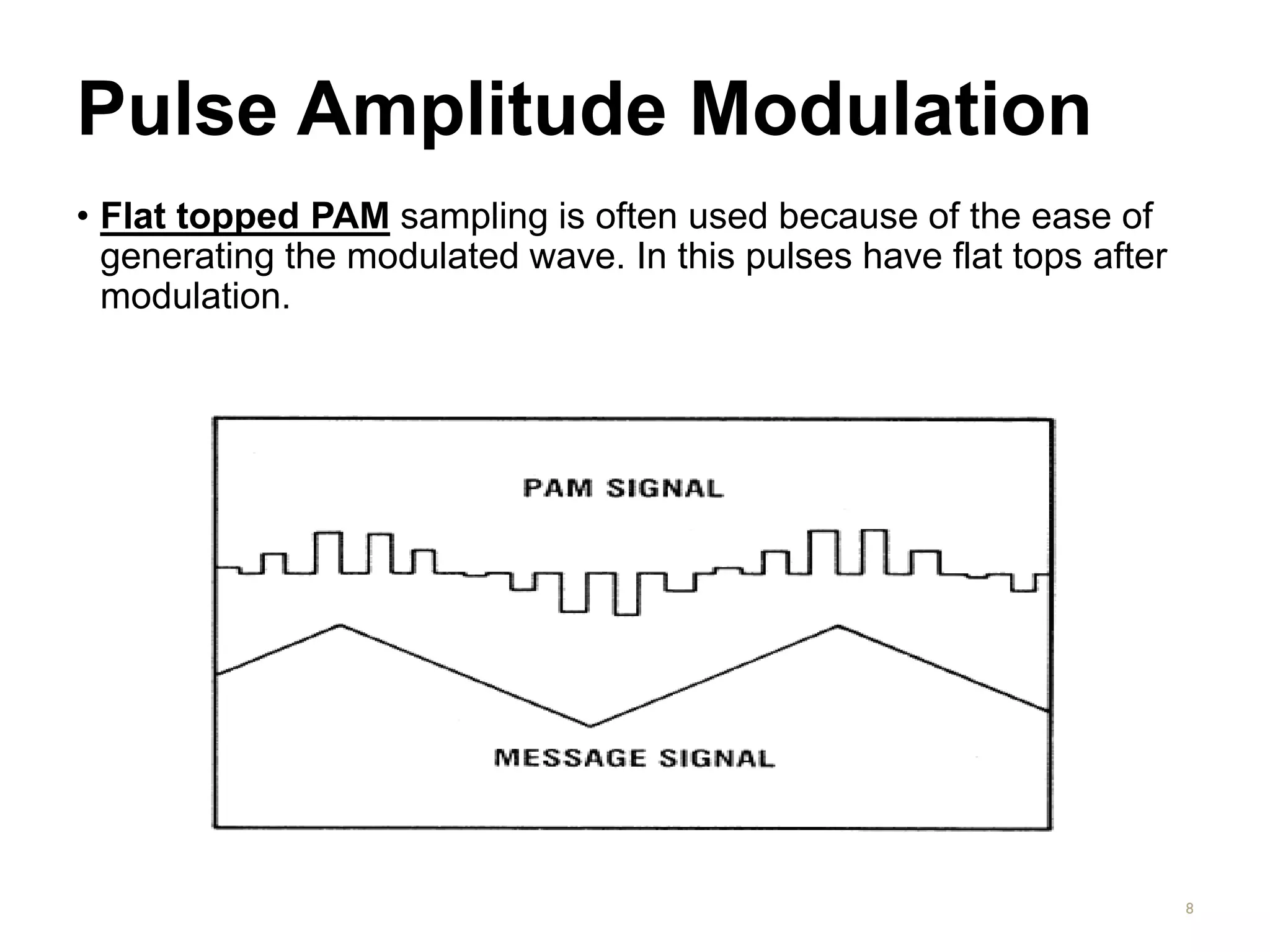
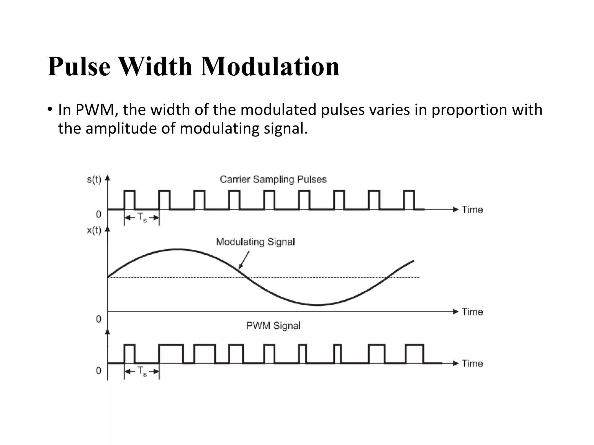
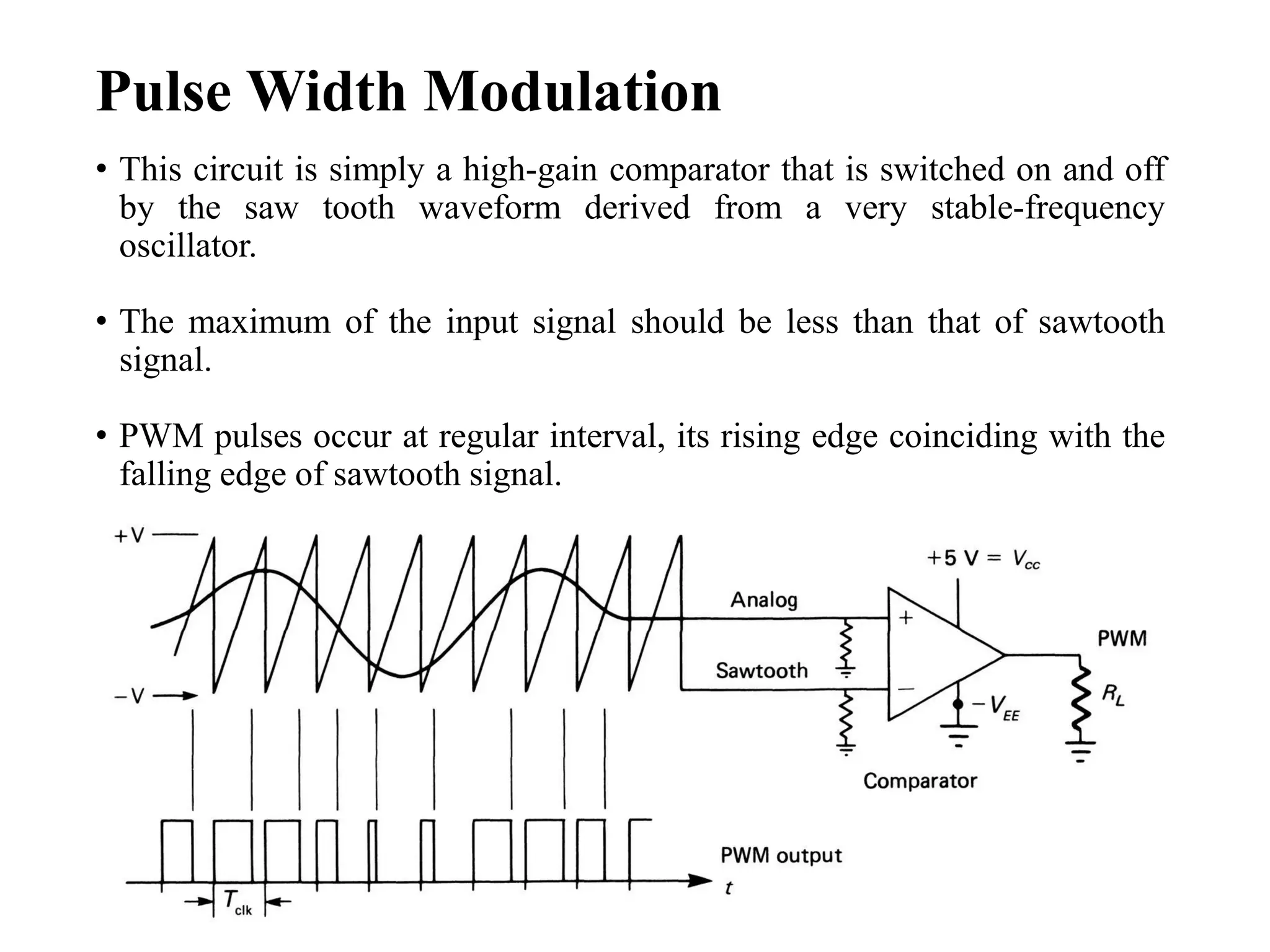
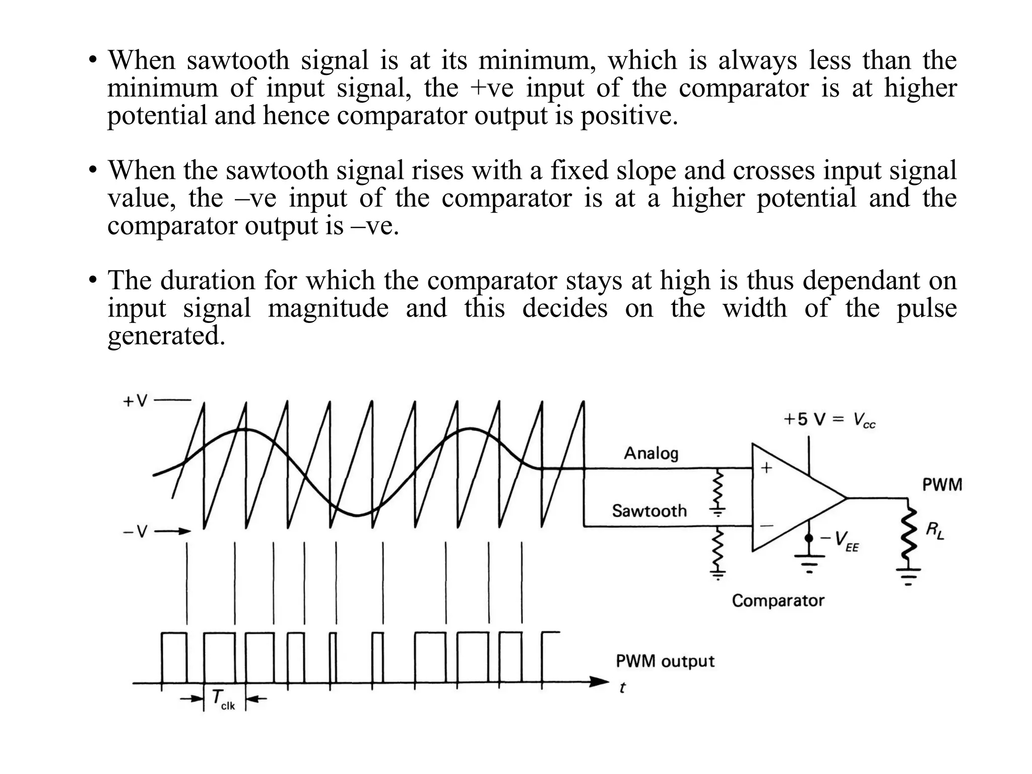
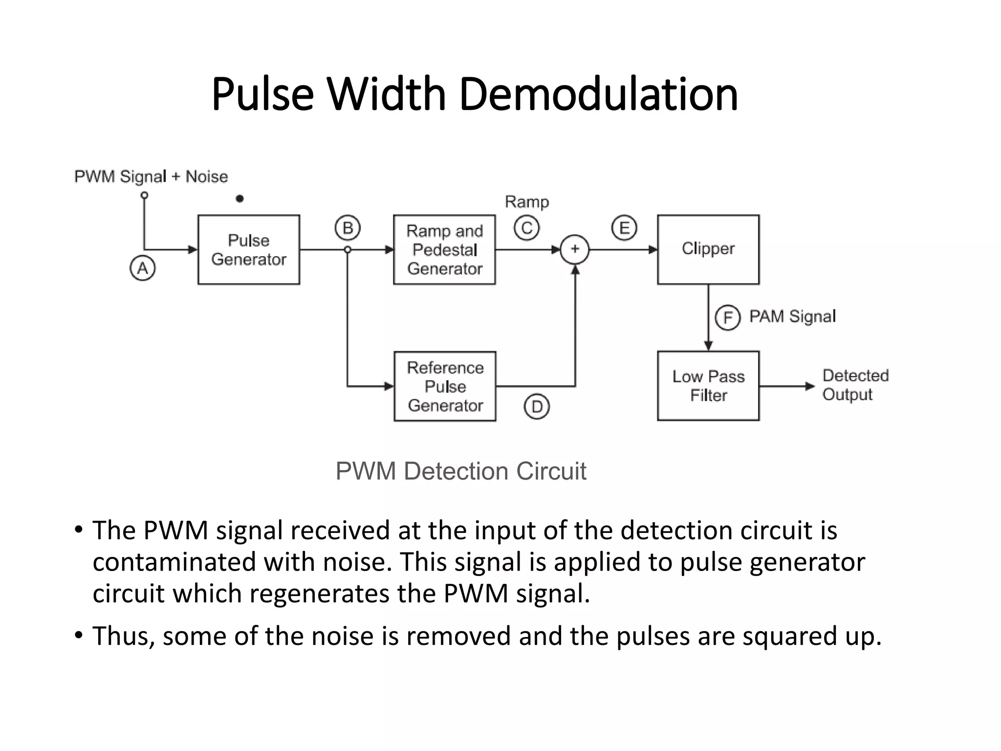
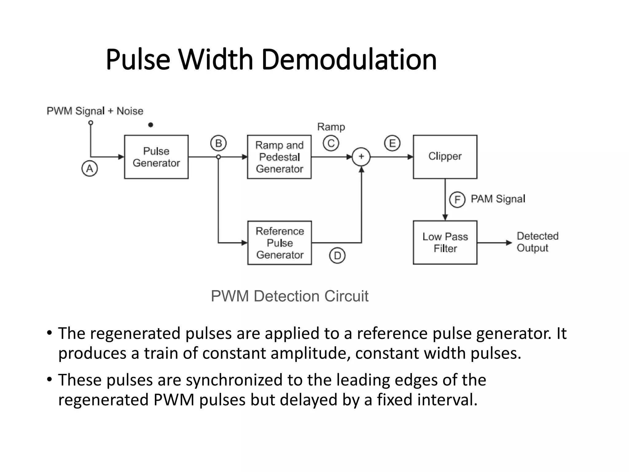
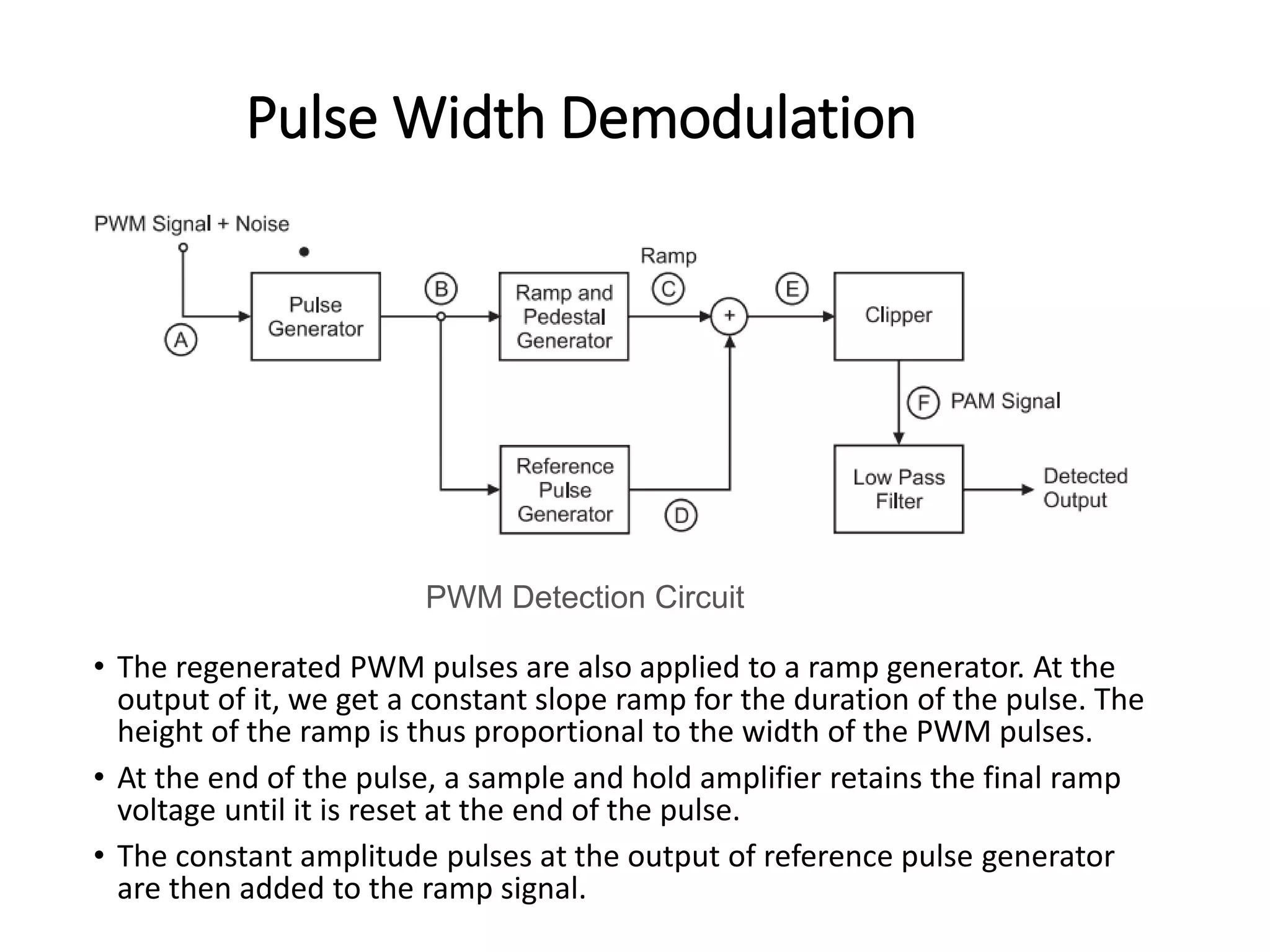
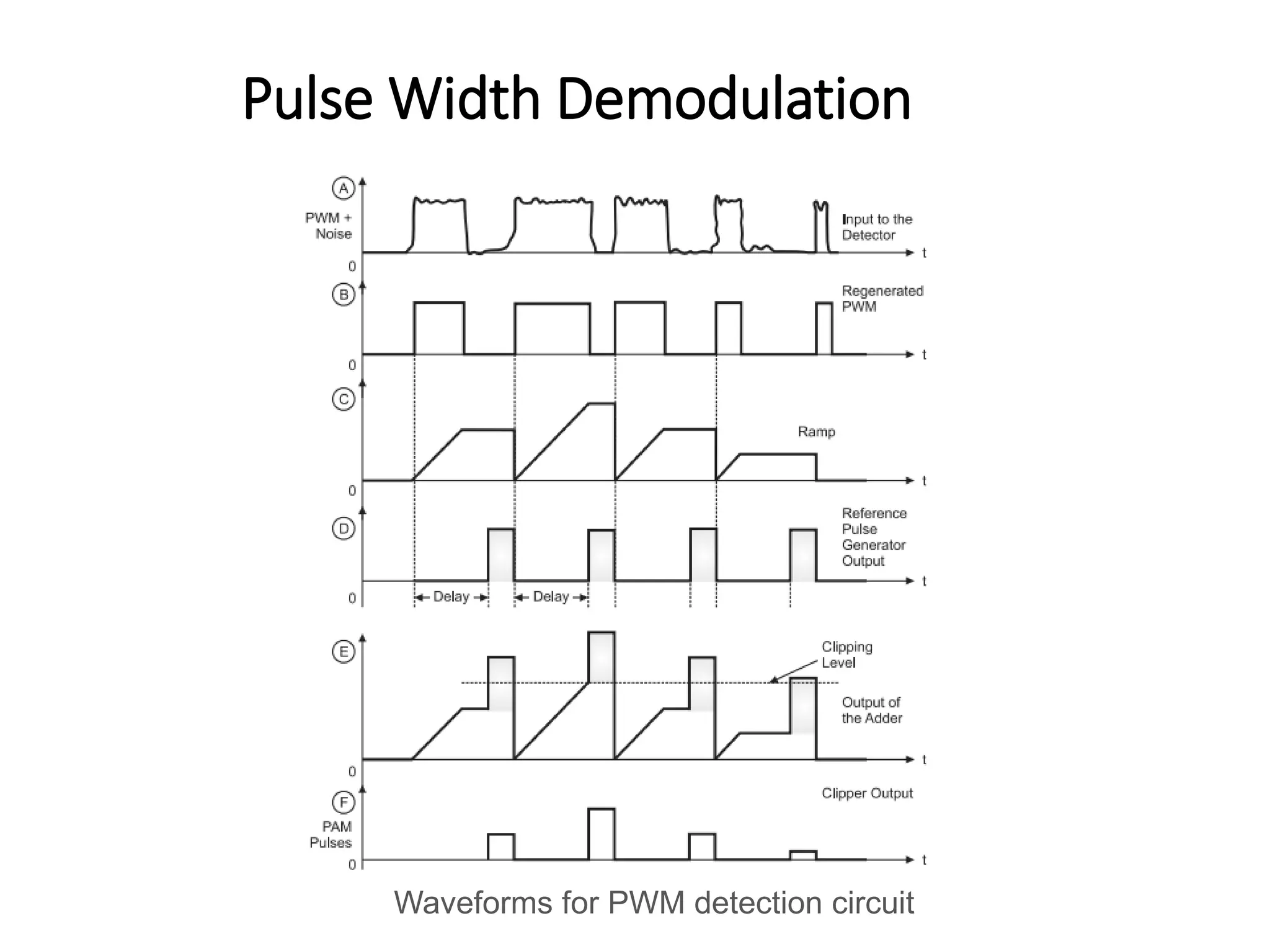
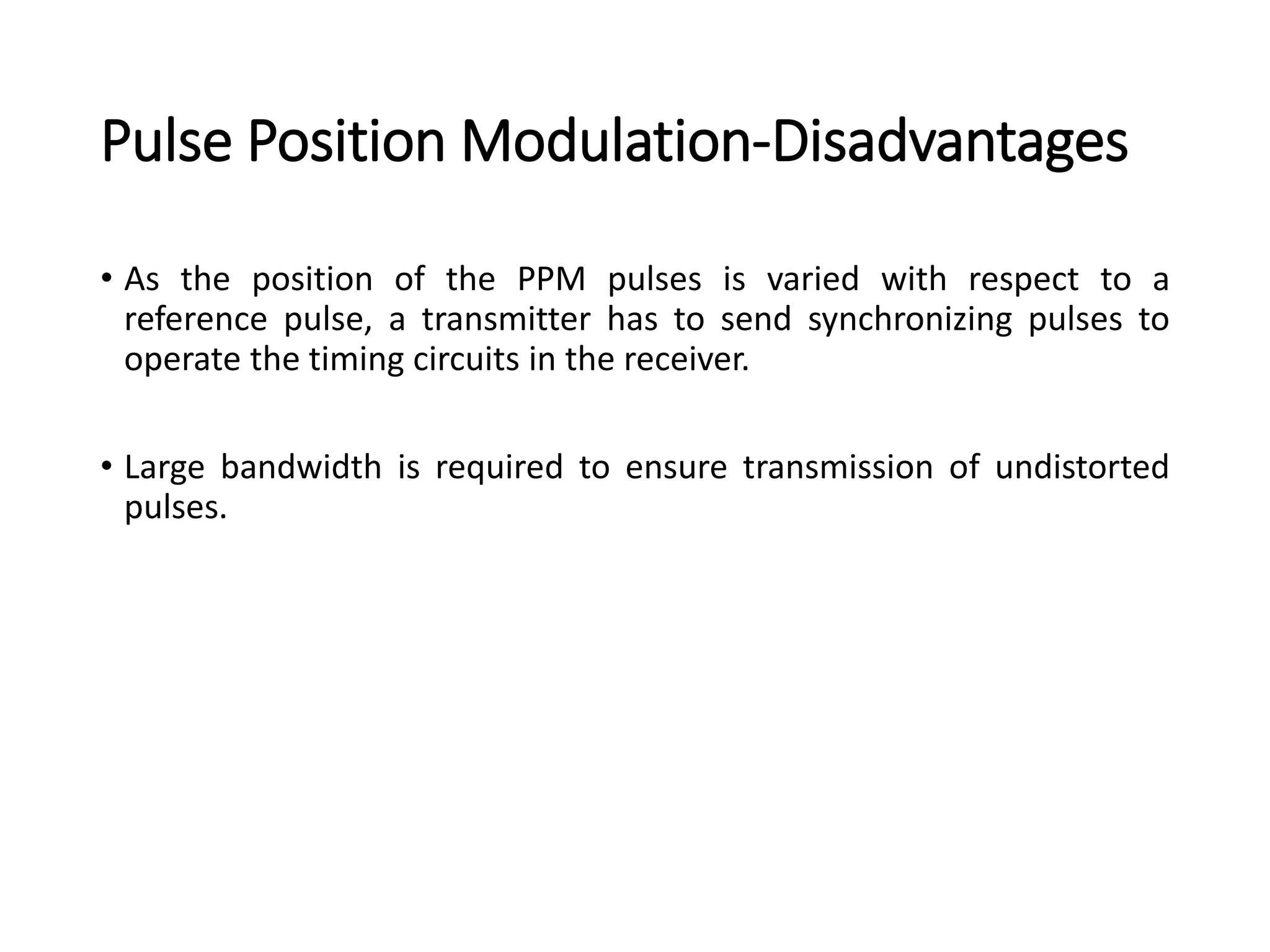
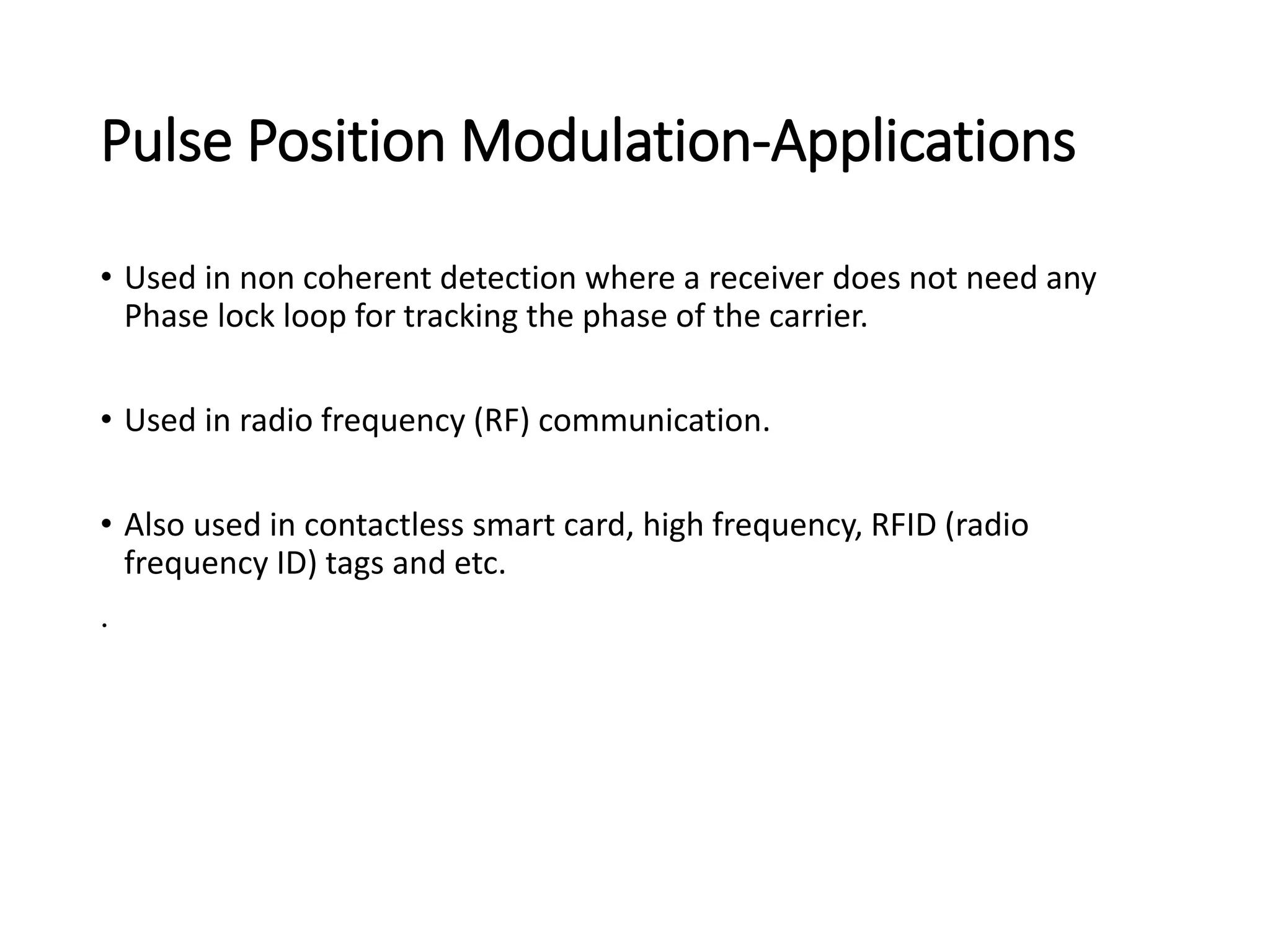
Pulse Modulation Systems
Dr. G.Aarthi,
Associate Professor, School of Electronics Engineering
Pulse Modulation
• Continuous-wave (CW) modulation (recap):
• A parameter of a sinusoidal carrier wave is varied continuously in
accordance with the message signal.
• Amplitude
• Frequency
• Phase
• Pulse Modulation:
• Analog pulse modulation: A periodic pulse train is used as a carrier.
The following parameters of the pulse are modified in accordance with
the message signal. Signal is transmitted at discrete intervals of time.
• Pulse amplitude
• Pulse width
• Pulse position
• Digital Pulse Modulation: Message signal represented in a form that
is discrete in both amplitude and time.
• The signal is transmitted as a sequence of coded pulses and No continuous wave in this form
of transmission
Analog Pulse Modulation
•Pulse Amplitude Modulation
• Amplitudes of regularly spaced pulses varied in proportion to the
corresponding sampled values of a continuous message signal.
• Pulse-amplitude modulation is similar to natural sampling, where the
message signal is multiplied by a periodic train of rectangular pulses.
• In natural sampling the top of each modulated rectangular pulse varies
with the message signal.
PAM Signal
Other forms of Pulse Modulation
• Pulse Width Modulation (PWM)
• Also referred to as Pulse Duration Modulation (PDM) where
samples of the message signal are used to vary the duration of
the individual pulses in the carrier.
• Pulse Position Modulation (PPM)
• The position of a pulse relative to its unmodulated time of
occurrence is varied in accordance with the message signal.
Other forms of Pulse Modulation
Pulse Amplitude Modulation
Low
Pass
Filter
6
Multiplier
Pulse
train
generator
Modulating
Signal PAM
Signal
The carrier is in the form of narrow pulses having
frequency fs.The uniform sampling takes place
in multiplier to generate PAM signal.Samples are
placed Ts sec away from each other.
Pulse Amplitude Modulation
• Depending upon the shape and polarity of the sampled pulses,
PAM is of two types,
• Natural PAM sampling occurs when top portion of the pulses are
subjected to follow the modulating wave.
7
Pulse Amplitude Modulation
• Flat topped PAM sampling is often used because of the ease of
generating the modulated wave. In this pulses have flat tops after
modulation.
8
PAM Detection
• The PAM signal can be detected by passing it through a low pass
filter.
9
9
PAM Advantages
• Through pulse amplitude modulation data transformation is done
efficiently.
• It is the quick way of data transfer
• It is the simplest form on base of which all digital or modern
modulation techniques work
PAM Disadvantages
• Amplitude variation occurs as the result of which the receiver's peak
power varies with it.
• In the transmission of pulse amplitude modulation signals very large
bandwidth are required.
PAM Applications
• It is used in Ethernet communication.
• It is used in many micro-controllers for generating control signals.
• It is used in Photo-biology.
• It is used as an electronic driver for LED lighting.
Pulse Width Modulation
• In PWM, the width of the modulated pulses varies in proportion with
the amplitude of modulating signal.
Pulse Width Modulation
• This circuit is simply a high-gain comparator that is switched on and off
by the saw tooth waveform derived from a very stable-frequency
oscillator.
• The maximum of the input signal should be less than that of sawtooth
signal.
• PWM pulses occur at regular interval, its rising edge coinciding with the
falling edge of sawtooth signal.
• When sawtooth signal is at its minimum, which is always less than the
minimum of input signal, the +ve input of the comparator is at higher
potential and hence comparator output is positive.
• When the sawtooth signal rises with a fixed slope and crosses input signal
value, the –ve input of the comparator is at a higher potential and the
comparator output is –ve.
• The duration for which the comparator stays at high is thus dependant on
input signal magnitude and this decides on the width of the pulse
generated.
Pulse Width Demodulation
• The PWM signal received at the input of the detection circuit is
contaminated with noise. This signal is applied to pulse generator
circuit which regenerates the PWM signal.
• Thus, some of the noise is removed and the pulses are squared up.
PWM Detection Circuit
Pulse Width Demodulation
• The regenerated pulses are applied to a reference pulse generator. It
produces a train of constant amplitude, constant width pulses.
• These pulses are synchronized to the leading edges of the
regenerated PWM pulses but delayed by a fixed interval.
PWM Detection Circuit
Pulse Width Demodulation
• The regenerated PWM pulses are also applied to a ramp generator. At the
output of it, we get a constant slope ramp for the duration of the pulse. The
height of the ramp is thus proportional to the width of the PWM pulses.
• At the end of the pulse, a sample and hold amplifier retains the final ramp
voltage until it is reset at the end of the pulse.
• The constant amplitude pulses at the output of reference pulse generator
are then added to the ramp signal.
PWM Detection Circuit
Pulse Width Demodulation
• The output of the adder is then clipped off at a threshold level to
generate a PAM signal at the output of the clipper.
• A low pass filter is used to recover the original modulating signal back
from the PAM signal.
PWM Detection Circuit
Pulse Width Demodulation
Waveforms for PWM detection circuit
Pulse Width Modulation-Advantages
• Less effect of noise i.e., very good noise immunity.
• Synchronization between the transmitter and receiver is not essential
(Which is essential in PPM).
• It is possible to reconstruct the PWM signal from a noise,
contaminated PWM, as discussed in the detection circuit. Thus, it is
possible to separate out signal from noise (which is not possible in
PAM).
Pulse Width Modulation-Disadvantages
• Due to the variable pulse width, the pulses have variable power
contents. Hence, the transmission must be powerful enough to
handle the maximum width, pulse, though the average power
transmitted can be as low as 50% of this maximum power.
• In order to avoid any waveform distortion, the bandwidth required
for the PWM communication is large as compared to bandwidth of
PAM.
Pulse Width Modulation-Applications
• PWM finds application in motor control, in delivery of power which is
precisely regulated by regulating the width of the pulse.
Pulse Position Modulation
• In PPM, the amplitude and width of the pulses is kept constant but the
position of each pulse is varied in accordance with the amplitudes of the
sampled values of the modulating signal.
• The position of the pulses is changed with respect to the position of
reference pulses.
• The PPM pulses can be derived from the PWM pulses
Pulse Position Modulation
• The vertical dotted lines drawn are treated as reference lines to measure
the shift in position of PPM pulses.
• The PPM pulses marked 1, 2 and 3 go away from their respective
reference lines. This is corresponding to increase in the modulating
signal amplitude.
• Then, as the modulating voltage decreases, the PPM pulses 4, 5, 6, 7
come progressively closer to their respective reference lines.
Generation of PPM Signal
• The PPM signal can be generated from PWM signal
• The PWM pulses obtained at the comparator output are applied to a
monostable multivibrator.
• The monostable is negative edge triggered.
Generation of PPM Signal
• Hence, corresponding to each trailing edge of the PWM signal, the
monostable output goes high.
• It remains high for a fixed time decided by its own RC components.
• Thus as the trailing edges of the PWM signal keep shifting in proportion
with the modulating signal x(t), the PPM pulses also keep shifting.
Demodulation of PPM Signal
• The noise corrupted PPM waveform is received by the PPM demodulator
circuit.
• The pulse generator develops a pulsed waveform at its output of fixed
duration and applies these pulses to the reset pin (R) of a SR flip-flop.
• A fixed period reference pulse is generated from the incoming PPM
waveform and the SR flip-flop is set by the reference pulses.
• Due to the set and reset signals applied to the flip-flop, we get a PWM
signal at its output.
• The PWM signal can be demodulated using the PWM demodulator.
Pulse Position Modulation-Advantages
• Due to constant amplitude of PPM pulses, the information is not
contained in the amplitude. Hence, the noise added to PPM signal
does not distort the information. Thus, it has good noise immunity.
• It is possible to reconstruct PPM signal from the noise contaminated
PPM signal.
• Due to constant amplitude of pulses, the transmitted power always
remains constant.
Pulse Position Modulation-Disadvantages
• As the position of the PPM pulses is varied with respect to a
reference pulse, a transmitter has to send synchronizing pulses to
operate the timing circuits in the receiver.
• Large bandwidth is required to ensure transmission of undistorted
pulses.
Pulse Position Modulation-Applications
• Used in non coherent detection where a receiver does not need any
Phase lock loop for tracking the phase of the carrier.
• Used in radio frequency (RF) communication.
• Also used in contactless smart card, high frequency, RFID (radio
frequency ID) tags and etc.
.

22 PulseModulation.pdf

  • 1.
    Pulse Modulation Systems Dr.G.Aarthi, Associate Professor, School of Electronics Engineering
  • 2.
    Pulse Modulation • Continuous-wave(CW) modulation (recap): • A parameter of a sinusoidal carrier wave is varied continuously in accordance with the message signal. • Amplitude • Frequency • Phase • Pulse Modulation: • Analog pulse modulation: A periodic pulse train is used as a carrier. The following parameters of the pulse are modified in accordance with the message signal. Signal is transmitted at discrete intervals of time. • Pulse amplitude • Pulse width • Pulse position • Digital Pulse Modulation: Message signal represented in a form that is discrete in both amplitude and time. • The signal is transmitted as a sequence of coded pulses and No continuous wave in this form of transmission
  • 3.
    Analog Pulse Modulation •PulseAmplitude Modulation • Amplitudes of regularly spaced pulses varied in proportion to the corresponding sampled values of a continuous message signal. • Pulse-amplitude modulation is similar to natural sampling, where the message signal is multiplied by a periodic train of rectangular pulses. • In natural sampling the top of each modulated rectangular pulse varies with the message signal. PAM Signal
  • 4.
    Other forms ofPulse Modulation • Pulse Width Modulation (PWM) • Also referred to as Pulse Duration Modulation (PDM) where samples of the message signal are used to vary the duration of the individual pulses in the carrier. • Pulse Position Modulation (PPM) • The position of a pulse relative to its unmodulated time of occurrence is varied in accordance with the message signal.
  • 5.
    Other forms ofPulse Modulation
  • 6.
    Pulse Amplitude Modulation Low Pass Filter 6 Multiplier Pulse train generator Modulating SignalPAM Signal The carrier is in the form of narrow pulses having frequency fs.The uniform sampling takes place in multiplier to generate PAM signal.Samples are placed Ts sec away from each other.
  • 7.
    Pulse Amplitude Modulation •Depending upon the shape and polarity of the sampled pulses, PAM is of two types, • Natural PAM sampling occurs when top portion of the pulses are subjected to follow the modulating wave. 7
  • 8.
    Pulse Amplitude Modulation •Flat topped PAM sampling is often used because of the ease of generating the modulated wave. In this pulses have flat tops after modulation. 8
  • 9.
    PAM Detection • ThePAM signal can be detected by passing it through a low pass filter. 9 9
  • 10.
    PAM Advantages • Throughpulse amplitude modulation data transformation is done efficiently. • It is the quick way of data transfer • It is the simplest form on base of which all digital or modern modulation techniques work
  • 11.
    PAM Disadvantages • Amplitudevariation occurs as the result of which the receiver's peak power varies with it. • In the transmission of pulse amplitude modulation signals very large bandwidth are required.
  • 12.
    PAM Applications • Itis used in Ethernet communication. • It is used in many micro-controllers for generating control signals. • It is used in Photo-biology. • It is used as an electronic driver for LED lighting.
  • 13.
    Pulse Width Modulation •In PWM, the width of the modulated pulses varies in proportion with the amplitude of modulating signal.
  • 14.
    Pulse Width Modulation •This circuit is simply a high-gain comparator that is switched on and off by the saw tooth waveform derived from a very stable-frequency oscillator. • The maximum of the input signal should be less than that of sawtooth signal. • PWM pulses occur at regular interval, its rising edge coinciding with the falling edge of sawtooth signal.
  • 15.
    • When sawtoothsignal is at its minimum, which is always less than the minimum of input signal, the +ve input of the comparator is at higher potential and hence comparator output is positive. • When the sawtooth signal rises with a fixed slope and crosses input signal value, the –ve input of the comparator is at a higher potential and the comparator output is –ve. • The duration for which the comparator stays at high is thus dependant on input signal magnitude and this decides on the width of the pulse generated.
  • 16.
    Pulse Width Demodulation •The PWM signal received at the input of the detection circuit is contaminated with noise. This signal is applied to pulse generator circuit which regenerates the PWM signal. • Thus, some of the noise is removed and the pulses are squared up. PWM Detection Circuit
  • 17.
    Pulse Width Demodulation •The regenerated pulses are applied to a reference pulse generator. It produces a train of constant amplitude, constant width pulses. • These pulses are synchronized to the leading edges of the regenerated PWM pulses but delayed by a fixed interval. PWM Detection Circuit
  • 18.
    Pulse Width Demodulation •The regenerated PWM pulses are also applied to a ramp generator. At the output of it, we get a constant slope ramp for the duration of the pulse. The height of the ramp is thus proportional to the width of the PWM pulses. • At the end of the pulse, a sample and hold amplifier retains the final ramp voltage until it is reset at the end of the pulse. • The constant amplitude pulses at the output of reference pulse generator are then added to the ramp signal. PWM Detection Circuit
  • 19.
    Pulse Width Demodulation •The output of the adder is then clipped off at a threshold level to generate a PAM signal at the output of the clipper. • A low pass filter is used to recover the original modulating signal back from the PAM signal. PWM Detection Circuit
  • 20.
    Pulse Width Demodulation Waveformsfor PWM detection circuit
  • 21.
    Pulse Width Modulation-Advantages •Less effect of noise i.e., very good noise immunity. • Synchronization between the transmitter and receiver is not essential (Which is essential in PPM). • It is possible to reconstruct the PWM signal from a noise, contaminated PWM, as discussed in the detection circuit. Thus, it is possible to separate out signal from noise (which is not possible in PAM).
  • 22.
    Pulse Width Modulation-Disadvantages •Due to the variable pulse width, the pulses have variable power contents. Hence, the transmission must be powerful enough to handle the maximum width, pulse, though the average power transmitted can be as low as 50% of this maximum power. • In order to avoid any waveform distortion, the bandwidth required for the PWM communication is large as compared to bandwidth of PAM.
  • 23.
    Pulse Width Modulation-Applications •PWM finds application in motor control, in delivery of power which is precisely regulated by regulating the width of the pulse.
  • 24.
    Pulse Position Modulation •In PPM, the amplitude and width of the pulses is kept constant but the position of each pulse is varied in accordance with the amplitudes of the sampled values of the modulating signal. • The position of the pulses is changed with respect to the position of reference pulses. • The PPM pulses can be derived from the PWM pulses
  • 25.
    Pulse Position Modulation •The vertical dotted lines drawn are treated as reference lines to measure the shift in position of PPM pulses. • The PPM pulses marked 1, 2 and 3 go away from their respective reference lines. This is corresponding to increase in the modulating signal amplitude. • Then, as the modulating voltage decreases, the PPM pulses 4, 5, 6, 7 come progressively closer to their respective reference lines.
  • 26.
    Generation of PPMSignal • The PPM signal can be generated from PWM signal • The PWM pulses obtained at the comparator output are applied to a monostable multivibrator. • The monostable is negative edge triggered.
  • 27.
    Generation of PPMSignal • Hence, corresponding to each trailing edge of the PWM signal, the monostable output goes high. • It remains high for a fixed time decided by its own RC components. • Thus as the trailing edges of the PWM signal keep shifting in proportion with the modulating signal x(t), the PPM pulses also keep shifting.
  • 28.
    Demodulation of PPMSignal • The noise corrupted PPM waveform is received by the PPM demodulator circuit. • The pulse generator develops a pulsed waveform at its output of fixed duration and applies these pulses to the reset pin (R) of a SR flip-flop. • A fixed period reference pulse is generated from the incoming PPM waveform and the SR flip-flop is set by the reference pulses. • Due to the set and reset signals applied to the flip-flop, we get a PWM signal at its output. • The PWM signal can be demodulated using the PWM demodulator.
  • 29.
    Pulse Position Modulation-Advantages •Due to constant amplitude of PPM pulses, the information is not contained in the amplitude. Hence, the noise added to PPM signal does not distort the information. Thus, it has good noise immunity. • It is possible to reconstruct PPM signal from the noise contaminated PPM signal. • Due to constant amplitude of pulses, the transmitted power always remains constant.
  • 30.
    Pulse Position Modulation-Disadvantages •As the position of the PPM pulses is varied with respect to a reference pulse, a transmitter has to send synchronizing pulses to operate the timing circuits in the receiver. • Large bandwidth is required to ensure transmission of undistorted pulses.
  • 31.
    Pulse Position Modulation-Applications •Used in non coherent detection where a receiver does not need any Phase lock loop for tracking the phase of the carrier. • Used in radio frequency (RF) communication. • Also used in contactless smart card, high frequency, RFID (radio frequency ID) tags and etc. .