Download as PDF, PPTX
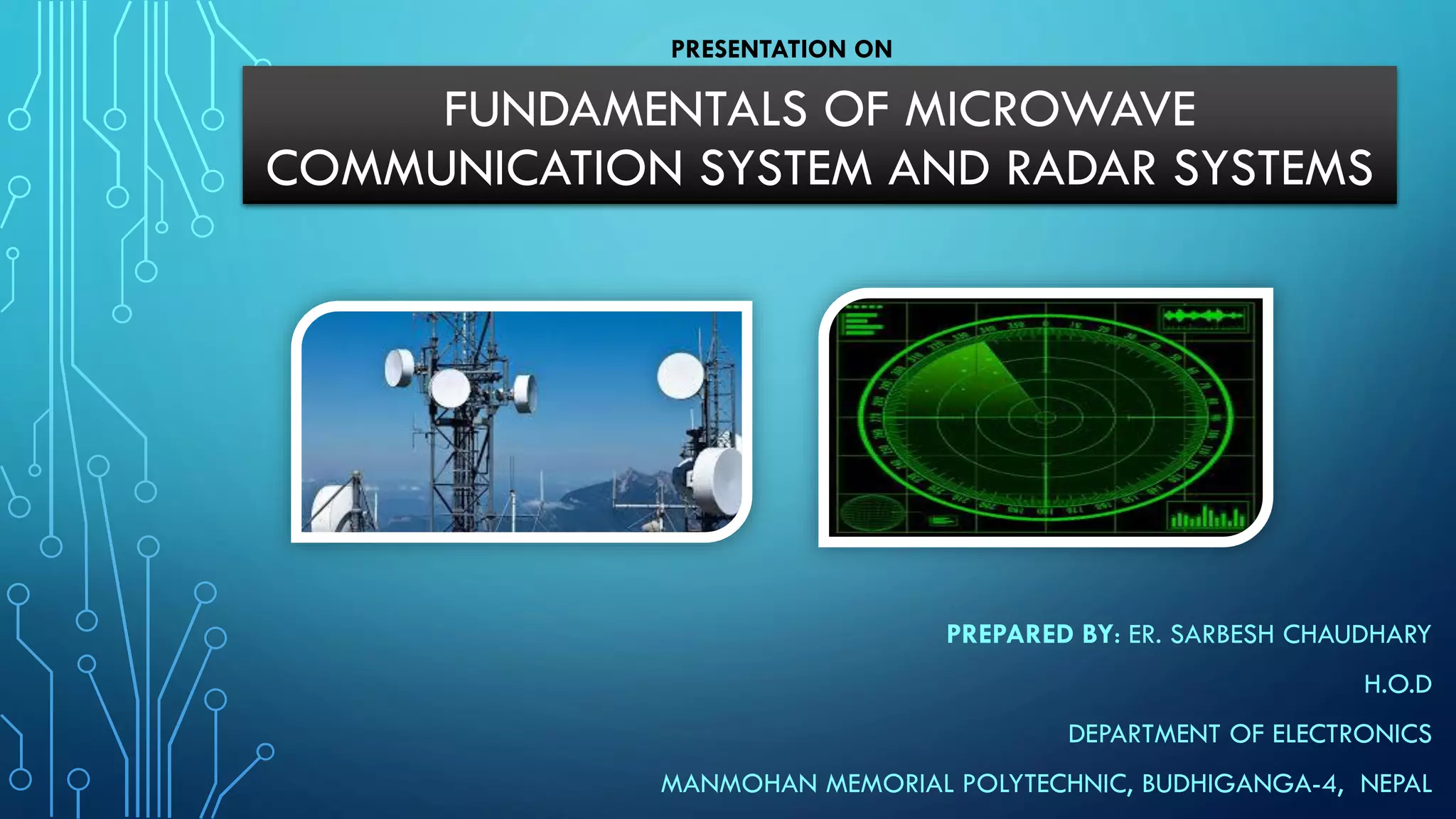
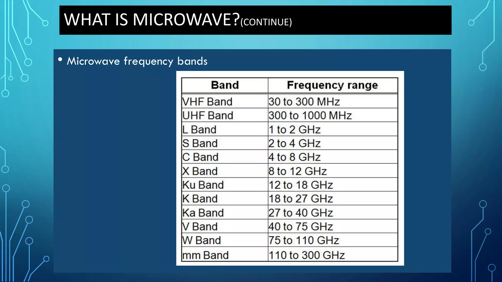
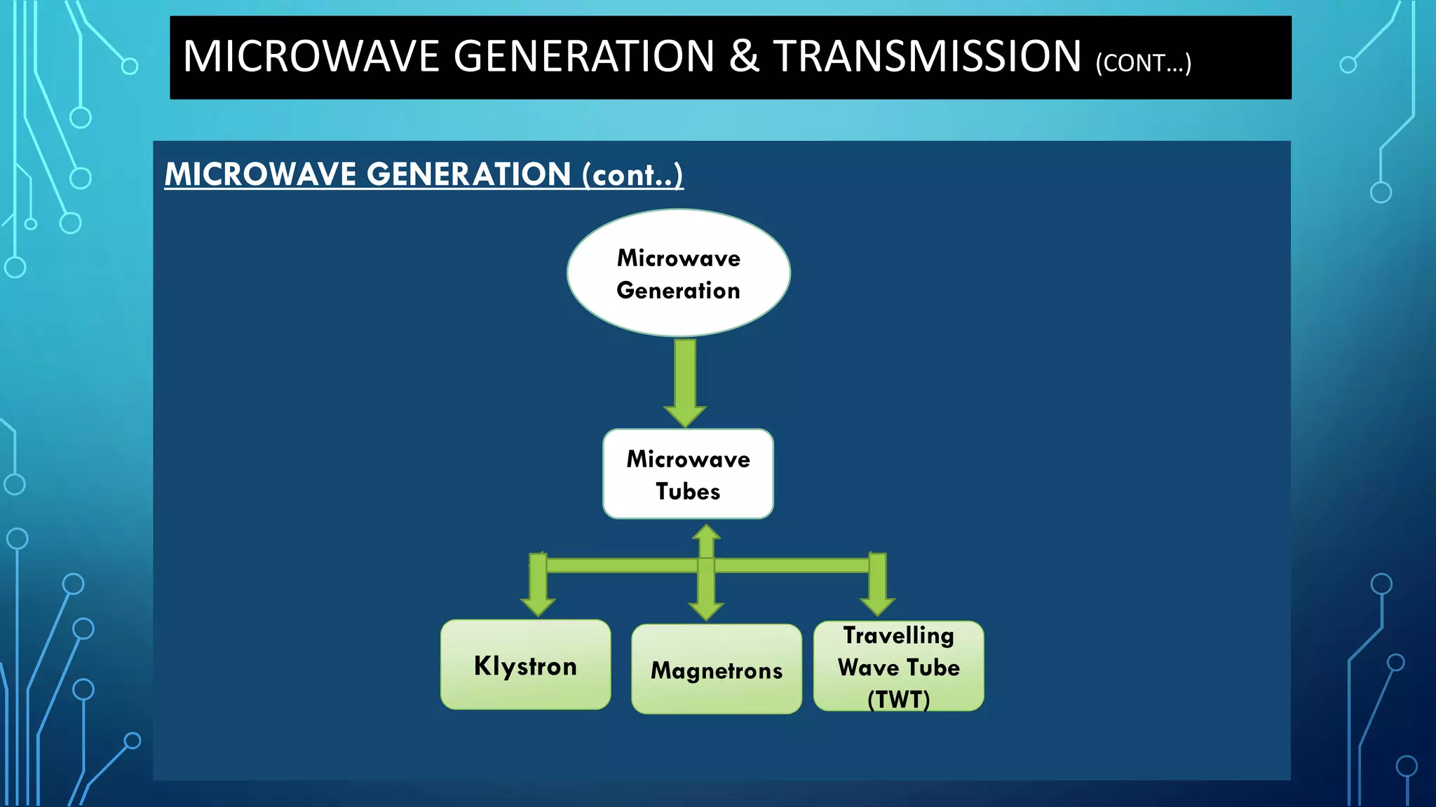
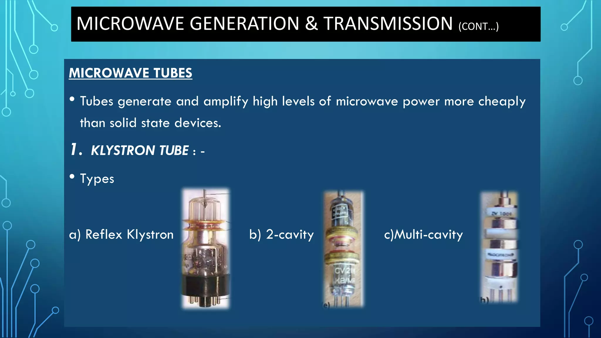
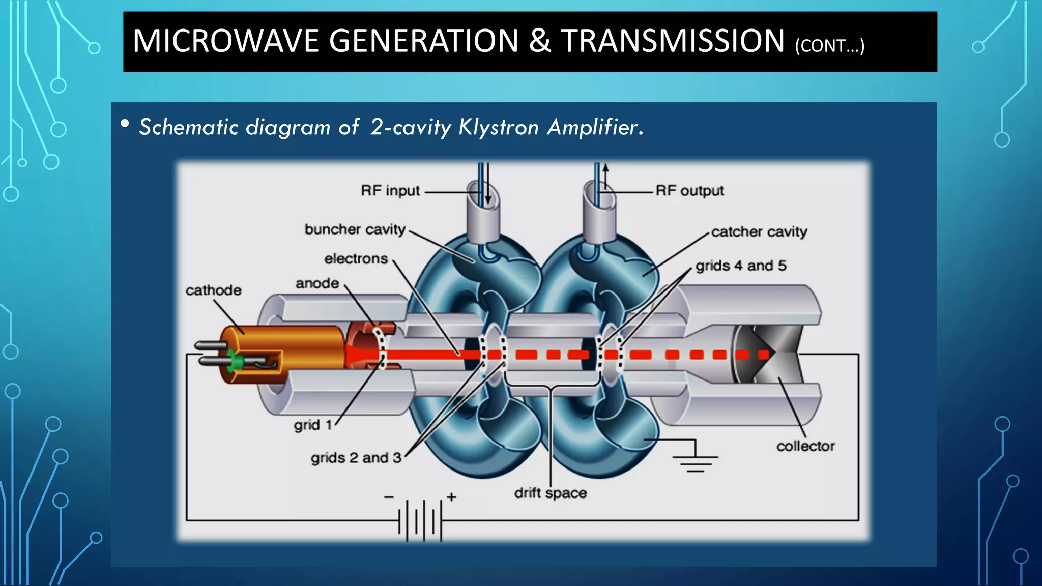
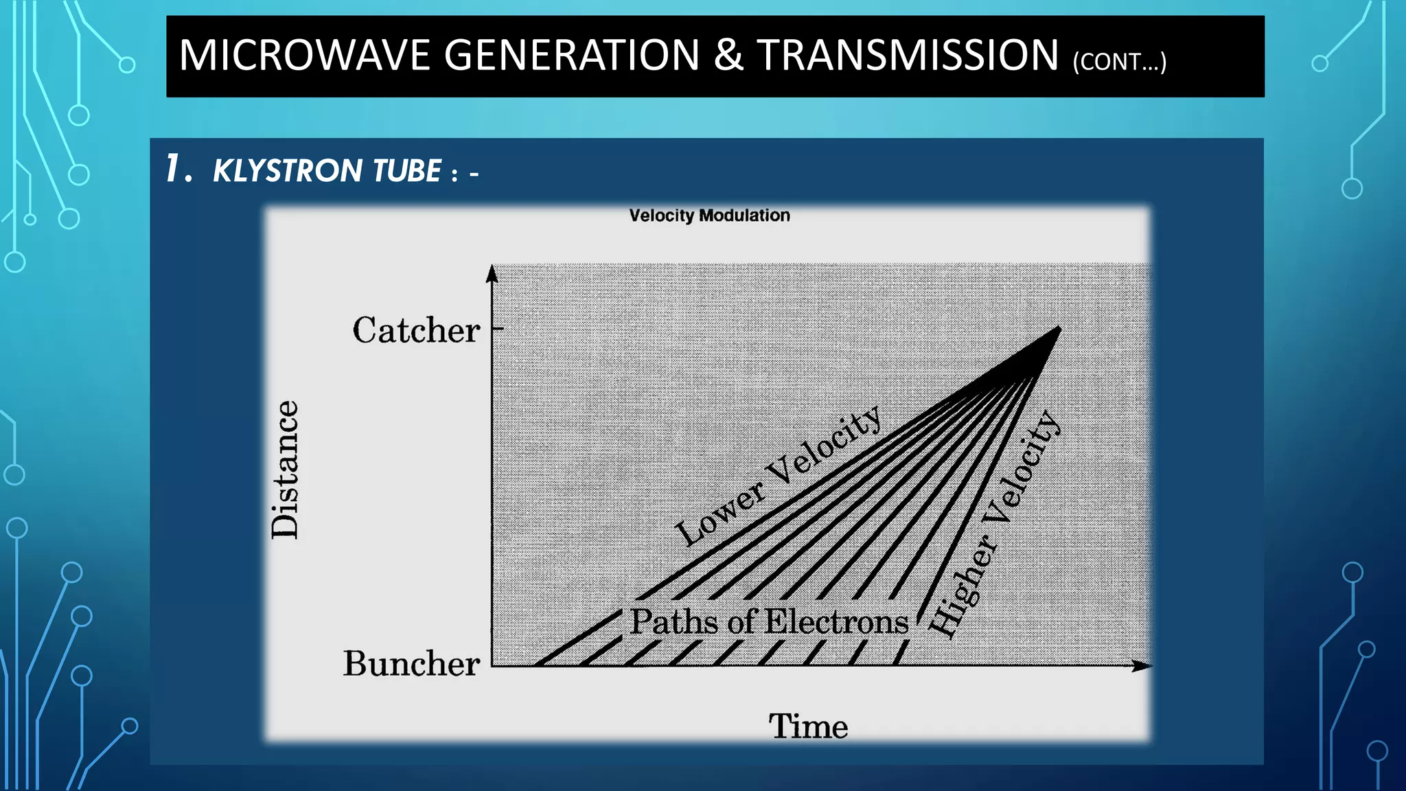
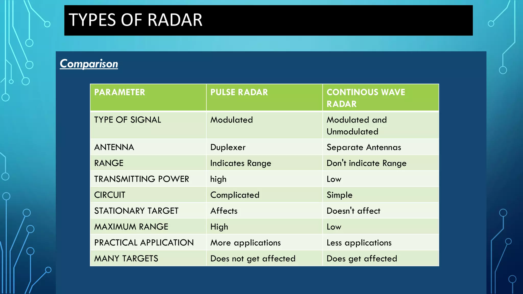
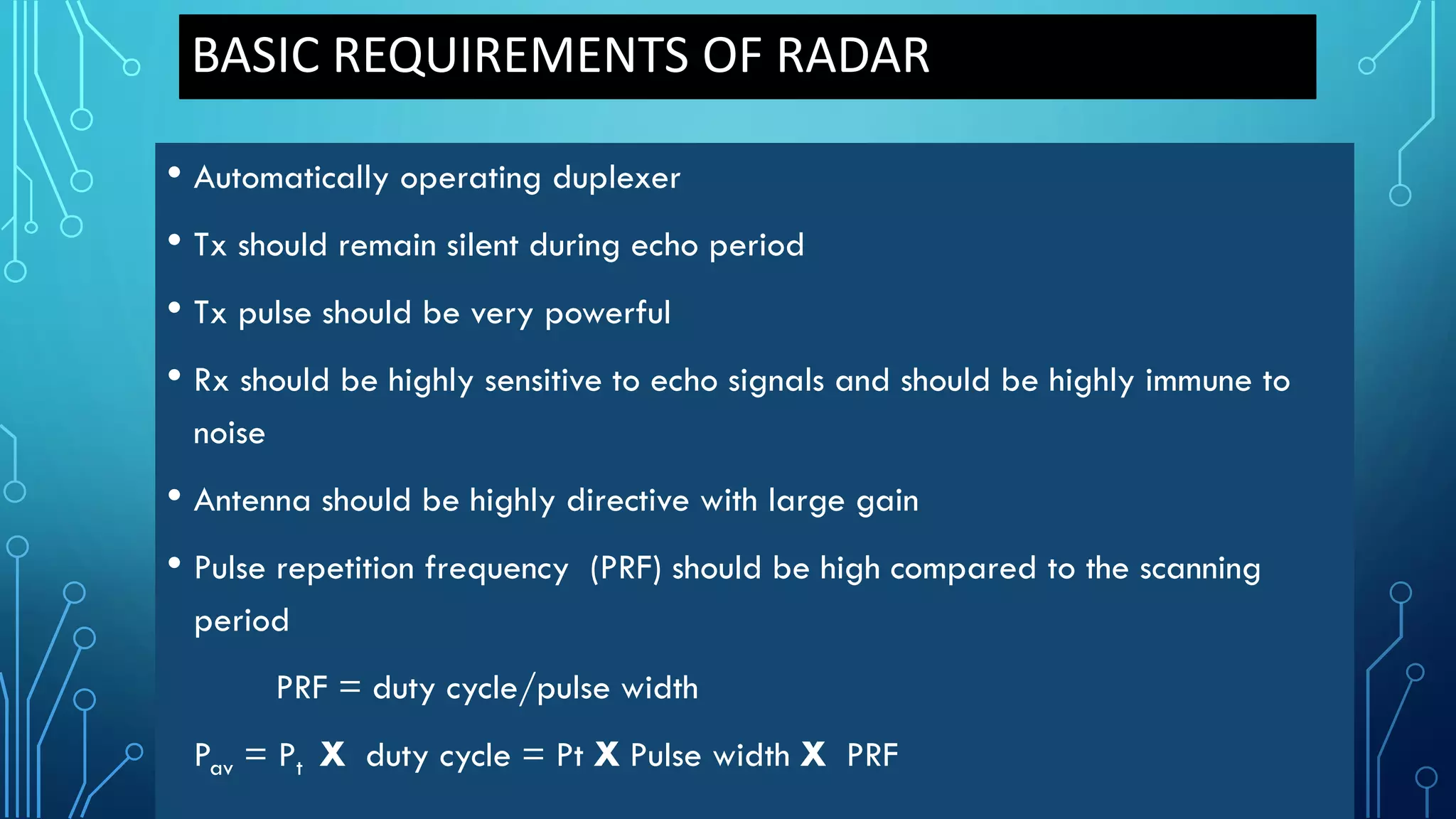
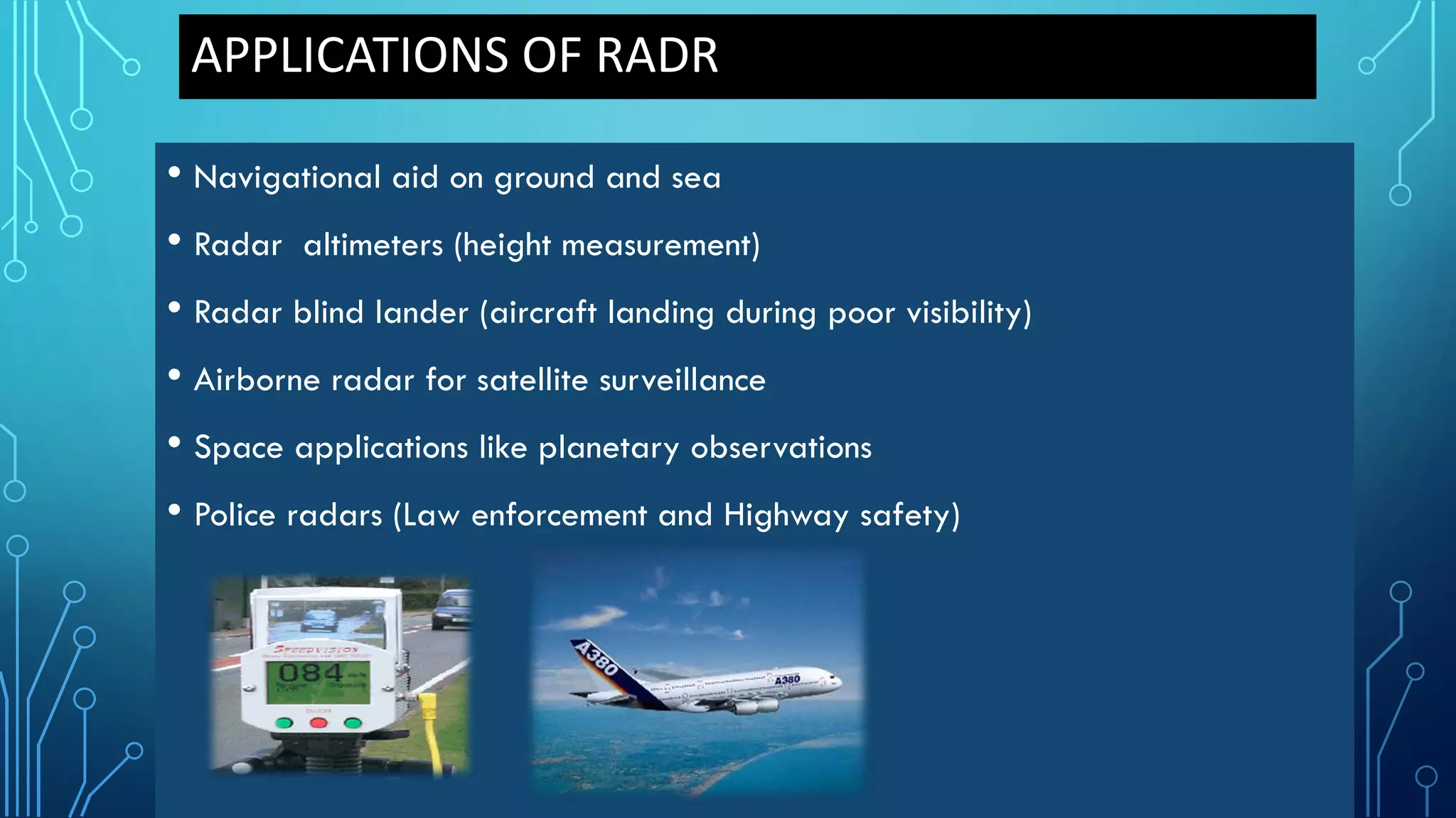
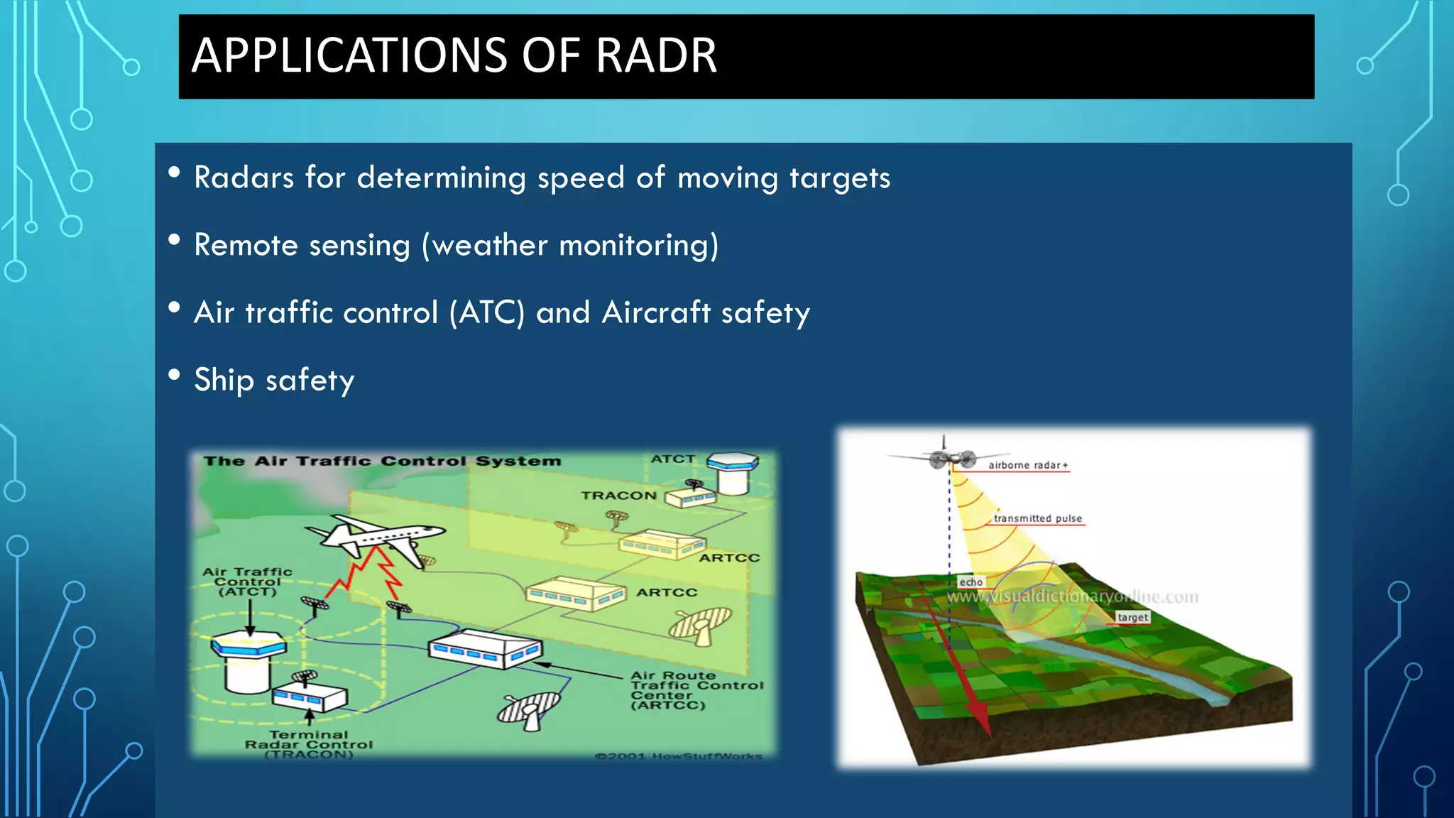
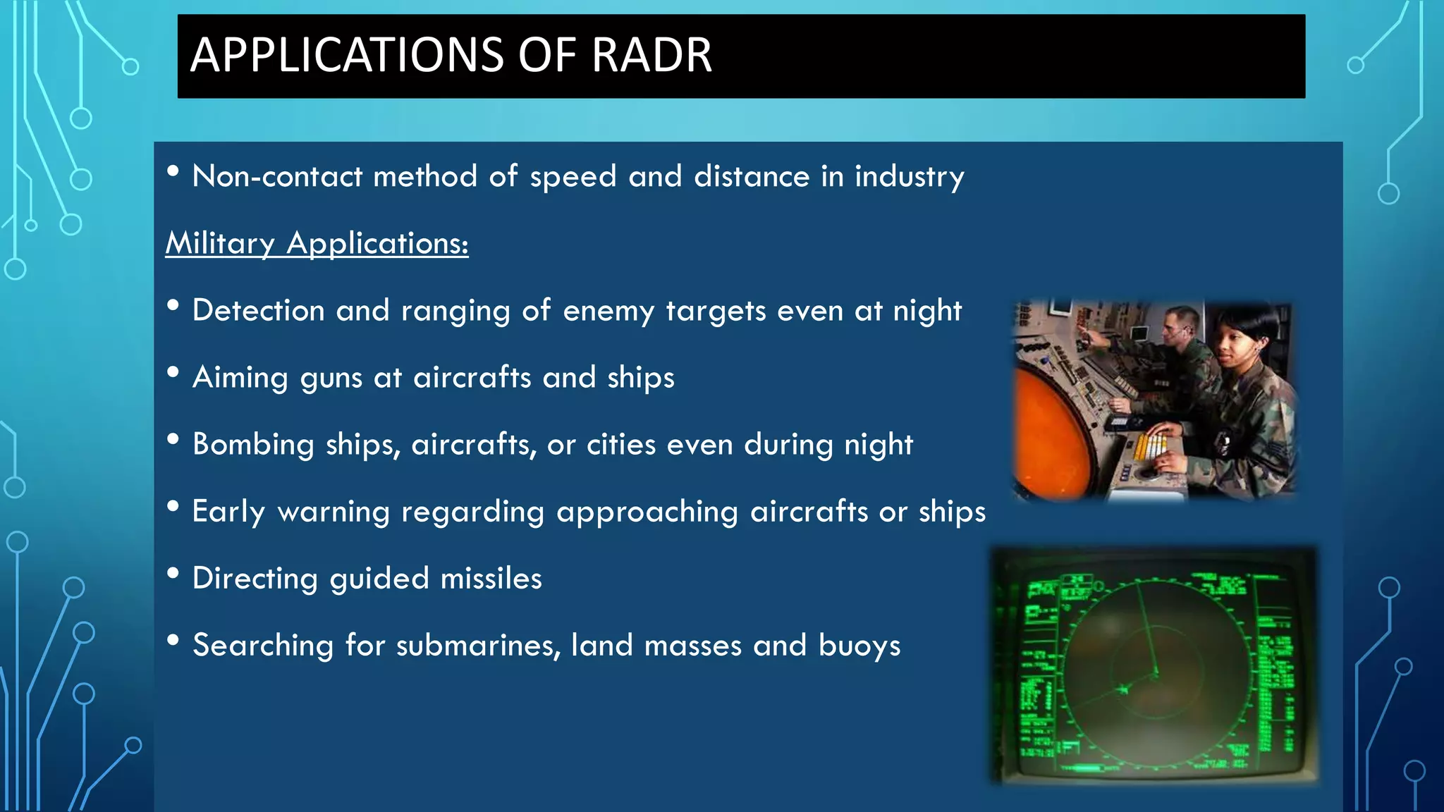


The document covers the fundamentals of microwave communication and radar systems, detailing microwave definitions, generation, transmission, and applications. It explains various microwave components like klystrons, magnetrons, and travelling wave tubes, as well as microwave antennas and propagation techniques. Additionally, the document outlines radar principles, types, requirements, and applications in telecommunications, navigation, and military contexts.


