Download to read offline


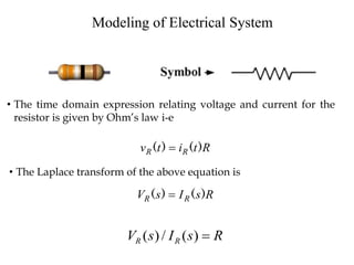
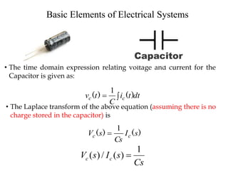
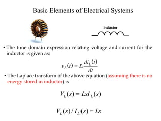

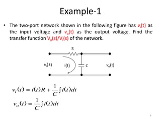
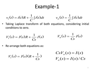

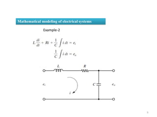
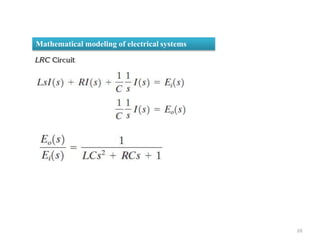
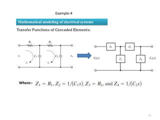


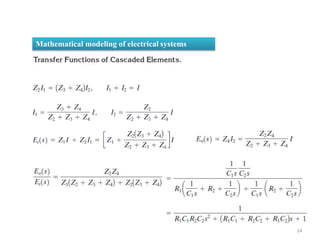

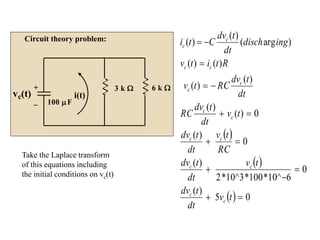

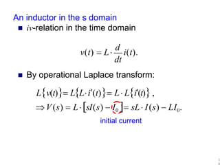
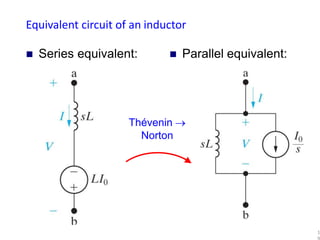
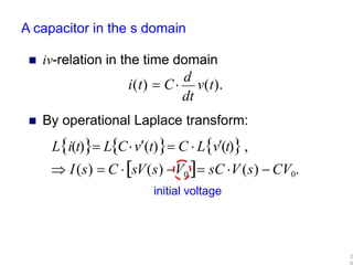
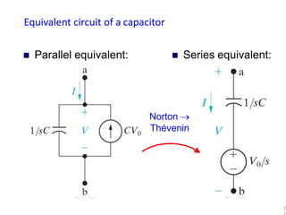

The document provides a comprehensive overview of modeling electrical systems, focusing on the basic elements such as resistors, capacitors, and inductors, including their time-domain expressions and Laplace transforms. It includes solved examples, demonstrating the calculation of transfer functions in two-port networks and analyzing circuits with initial conditions. The text illustrates how to apply Laplace transforms to various circuit theory problems involving electrical components.


![[Deck] What's New in Spark-Iceberg Integration via DSV2.pptx](https://cdn.slidesharecdn.com/ss_thumbnails/deckwhatsnewinspark-icebergintegrationviadsv2-260210005337-25955b12-thumbnail.jpg?width=640&height=640&fit=bounds)


