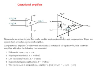
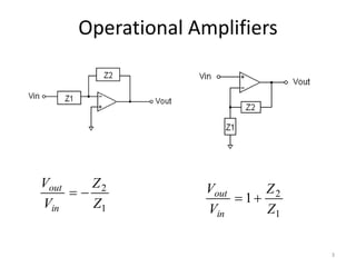
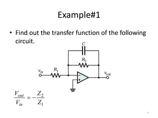
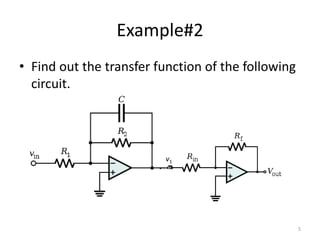
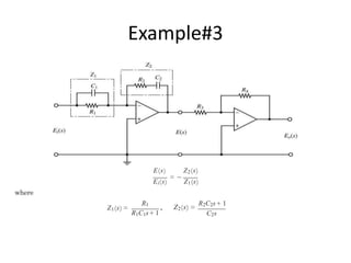
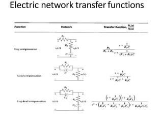
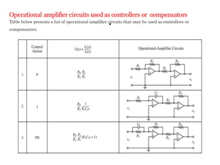
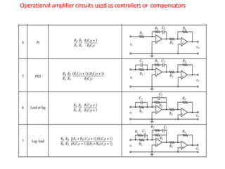
This document discusses modeling electronic systems using operational amplifiers. It provides operational amplifier basics, examples of calculating transfer functions of operational amplifier circuits, and discusses using operational amplifiers for lead/lag compensation and PID controllers. Specifically, it gives examples of calculating transfer functions, discusses electric network transfer functions, and provides a table of common operational amplifier circuits that can be used as controllers or compensators.
UNIT - III
FETs and Digital Circuits: FETs: JFET, V-I characteristics, MOSFET, low frequency CS and CD amplifiers, CS and CD amplifiers.
Digital Circuits: Digital (binary) operations of a system, OR gate, AND gate, NOT, EXCLUSIVE OR gate, De Morgan Laws, NAND and NOR DTL gates, modified DTL gates, HTL and TTL gates, output stages, RTL and DCTL, CMOS, Comparison of logic families.
Poles and Zeros of a transfer function are the frequencies for which the value of the denominator and numerator of transfer function becomes zero respectively. poles and zeros define the performance of a system.
This book guides the beginner to start up with Embedded C programming using MP LAB . This Book covers all interfacing examples with pic micro controller and guides beginners to develop projects on PIC micro controller
it covers topics Introduction
Classification of Logic Families
Important point
Level of Integration
Specification of Digital ICs
TTL Circuit
TTL NAND Gates
MOS/CMOS Circuits
CMOS NAND Gate
ECL Circuit
Comparison
Numbers of Digital ICs
November 21, 20131How a Diode WorksA diode is an electrica.docxhenrymartin15260
November 21, 2013
1
How a Diode Works
A diode is an electrical device allowing current to flow through in only one direction. The term “diode” is used if I ≤ 1 A. If I>1A, we use the term “rectifier,” although both terms are commonly considered interchangeable.
November 21, 2013
2
Theoretical Analysis of the Rectifier Circuit
Given the circuit below, R1=1.0 kΩ. Sketch theoretical waveforms for the input (CH-1) signal and the output (CH-2) signal when a 10 VPP 1.0 kHz sine wave is applied to the circuit. Predict the result.
November 21, 2013
3
Theoretical Analysis of the Rectifier Circuit- What should we observe (frequency? Amplitude?)
CH-1 (input signal):
(>>t=0:0.00001:6/2000; y=5*sin(2*pi*1000*t); plot(t,y), grid on)
What should be the output signal???
November 21, 2013
4
Simulation of the Rectifier Circuit – Record the Result
Adjust the settings
of the function generator
Accordingly
November 21, 2013
5
Construct the Rectifier Circuit – Record the Result
Compare the theoretical, simulation, and hardware circuit results and make your comments
November 21, 2013
6
Construct the Rectifier Circuit – the O-Scope Display
Hardware circuit oscilloscope display
November 21, 2013
7
Theoretical Analysis of the Filtered Rectifier Circuit
Given the circuit below, R1=1.0 kΩ, C1=10 uF. Sketch theoretical waveforms for the input (CH-1) signal and the output (CH-2) signal when a 10 VPP 1.0 kHz sine wave is applied to the circuit. Predict the result.
November 21, 2013
8
Theoretical Analysis of the Filtered Rectifier Circuit – Output Signal
Given input signal below, what should we observe at the output?
The diode is to change the AC to DC signal
The capacitor is to “smoothen” the DC signal
November 21, 2013
9
Simulation of the Filtered Rectifier Circuit – Record the Result
Adjust the settings
of the function generator
Accordingly
November 21, 2013
10
Construct the Filtered Rectifier Circuit – Record the Result
Compare the theoretical, simulation, and hardware circuit results and make your comments
November 21, 2013
11
Construct the Filtered Rectifier Circuit – O-Scope Display
Hardware circuit oscilloscope display (notice scale change for Channel 2 for better viewing of the output signal)
November 21, 2013
12
Voltage Regulation using Zener Diode – The Circuit
November 21, 2013
13
How a Zener Diode Works
Zener diodes are special diodes which work reverse-biased at breakdown - specific voltage (“Zener voltage”). They are designed to work continuously at that specific voltage - anywhere from 1.8 to 200 V.
November 21, 2013
14
How a Zener Diode Works – The Circuit Example
For the circuit below, the voltage across the Zener diode will be maintained at 10V.
November 21, 2013
15
Voltage Regulation using Zener Diode – MultiSim Simulation (Change Scale on Channel B to view signal more clearly)
Adjust the settings
of the function generator
Accordingly
November 21, 2013
16
Voltage Regulation using the Voltage.
Design and Implementation of Schmitt Trigger using Operational AmplifierIJERA Editor
A Schmitt trigger is an electronic circuit, a Comparator that is used to detect whether a voltage has crossed over a given reference level. It has two stable states and is very useful as signal conditioning device. When an input waveform in the form of sinusoidal waveform, triangular waveform, or any other periodic waveform is given, the Schmitt trigger will produce a Rectangular or square output waveform that has sharp leading and trailing edges. Such fast rise and fall times are desirable for all digital circuits. The state of the art presented in the paper is the design and implementation of Schmitt trigger using operational amplifier µA-741, generating a Rectangular waveform. Furthermore, the Schmitt trigger exhibiting hysteresis is also presented in the paper. Due to the phenomenon of hysteresis, the output transition from HIGH to LOW and LOW to HIGH will take place at various thresholds.
Presentation on Op-amp by Sourabh kumarSourabh Kumar
Visit Andro Root ( http:\\www.androroot.com ) for Tech. news and Smartphones.
Presentation on Op-amp(Operational Amplifier) by Sourabh kumar. B.tech Presentation,
Why Fourier Transform
General Properties & Symmetry relations
Formula and steps
magnitude and phase spectra
Convergence Condition
mean-square convergence
Gibbs phenomenon
Direct Delta
Energy Density Spectrum
. Types of Modulation(Analog)
Phase-Frequency Relationships
FM and PM basics
Frequency deviation
MODULATION INDEX
Classification of FM
Narrow Band FM (NBFM)
generating a narrowband FM signal.
Wide Band FM (WBFM).
Carson’s Rule
Generation of WBFM
Average Power
FM BANDWIDTH
Comparing Frequency Modulation to Phase Modulation
ROOT-LOCUS METHOD, Determine the root loci on the real axis /the asymptotes o...Waqas Afzal
Angle and Magnitude Conditions
Example of Root Locus
Steps
constructing a root-locus plot is to locate the open-loop poles and zeros in s-plane.
Determine the root loci on the real axis
Determine the asymptotes of the root loci
Determine the breakaway point.
Closed loop stability via root locus
time domain analysis, Rise Time, Delay time, Damping Ratio, Overshoot, Settli...Waqas Afzal
Time Response- Transient, Steady State
Standard Test Signals- U(t), S(t), R(t)
Analysis of First order system - for Step input
Analysis of second order system -for Step input
Time Response Specifications- Rise Time, Delay time, Damping Ratio, Overshoot, Settling Time
Calculations
state space representation,State Space Model Controllability and Observabilit...Waqas Afzal
State Variables of a Dynamical System
State Variable Equation
Why State space approach
Block Diagram Representation Of State Space Model
Controllability and Observability
Derive Transfer Function from State Space Equation
Time Response and State Transition Matrix
Eigen Value
introduction to modeling, Types of Models, Classification of mathematical mod...Waqas Afzal
Types of Systems
Ways to study system
Model
Types of Models
Why Mathematical Model
Classification of mathematical models
Black box, white box, Gray box
Lumped systems
Dynamic Systems
Simulation
laplace transform and inverse laplace, properties, Inverse Laplace Calculatio...Waqas Afzal
Laplace Transform
-Proof of common function
-properties
-Initial Value and Final Value Problems
Inverse Laplace Calculations
-by identification
-Partial fraction
Solution of Ordinary differential using Laplace and inverse Laplace
Transfer Function, Concepts of stability(critical, Absolute & Relative) Poles...Waqas Afzal
Transfer Function
The Order of Control Systems
Concepts of stability(critical, Absolute & Relative)
Poles, Zeros
Stability calculation
BIBO stability
Transient Response Characteristics
Signal Flow Graph, SFG and Mason Gain Formula, Example solved with Masson Gai...Waqas Afzal
Basic Properties of SFG
Definitions of SFG Terms
SFG Algebra
Relation between SFG and block diagram
Mason Gain Formula
Example solved with Masson Gain Formula
automatic control, Basic Definitions, Classification of Control systems, Requ...Waqas Afzal
Why automatic controls is required
2. Process Variables
controlled variable, manipulated variable
3. Functions of Automatic Control
Measurement
Comparison
Computation
Correction
4.Basic Definitions
System, Plant, Process, Controller, input, output, disturbance
5. Classification of Control systems
Natural, Manmade & Automatic control system
Open-Loop, Close-Loop control System
Linear Vs Nonlinear System
Time invariant vs Time variant
Continuous Data Vs Discrete Data System
Deterministic vs Stochastic System
6. Requirements of an ideal Control system
Accuracy, Sensitivity, noise, Bandwidth, Speed, Oscillations
Saudi Arabia stands as a titan in the global energy landscape, renowned for its abundant oil and gas resources. It's the largest exporter of petroleum and holds some of the world's most significant reserves. Let's delve into the top 10 oil and gas projects shaping Saudi Arabia's energy future in 2024.
Industrial Training at Shahjalal Fertilizer Company Limited (SFCL)MdTanvirMahtab2
This presentation is about the working procedure of Shahjalal Fertilizer Company Limited (SFCL). A Govt. owned Company of Bangladesh Chemical Industries Corporation under Ministry of Industries.
CFD Simulation of By-pass Flow in a HRSG module by R&R Consult.pptxR&R Consult
CFD analysis is incredibly effective at solving mysteries and improving the performance of complex systems!
Here's a great example: At a large natural gas-fired power plant, where they use waste heat to generate steam and energy, they were puzzled that their boiler wasn't producing as much steam as expected.
R&R and Tetra Engineering Group Inc. were asked to solve the issue with reduced steam production.
An inspection had shown that a significant amount of hot flue gas was bypassing the boiler tubes, where the heat was supposed to be transferred.
R&R Consult conducted a CFD analysis, which revealed that 6.3% of the flue gas was bypassing the boiler tubes without transferring heat. The analysis also showed that the flue gas was instead being directed along the sides of the boiler and between the modules that were supposed to capture the heat. This was the cause of the reduced performance.
Based on our results, Tetra Engineering installed covering plates to reduce the bypass flow. This improved the boiler's performance and increased electricity production.
It is always satisfying when we can help solve complex challenges like this. Do your systems also need a check-up or optimization? Give us a call!
Work done in cooperation with James Malloy and David Moelling from Tetra Engineering.
More examples of our work https://www.r-r-consult.dk/en/cases-en/
Overview of the fundamental roles in Hydropower generation and the components involved in wider Electrical Engineering.
This paper presents the design and construction of hydroelectric dams from the hydrologist’s survey of the valley before construction, all aspects and involved disciplines, fluid dynamics, structural engineering, generation and mains frequency regulation to the very transmission of power through the network in the United Kingdom.
Author: Robbie Edward Sayers
Collaborators and co editors: Charlie Sims and Connor Healey.
(C) 2024 Robbie E. Sayers
Sachpazis:Terzaghi Bearing Capacity Estimation in simple terms with Calculati...Dr.Costas Sachpazis
Terzaghi's soil bearing capacity theory, developed by Karl Terzaghi, is a fundamental principle in geotechnical engineering used to determine the bearing capacity of shallow foundations. This theory provides a method to calculate the ultimate bearing capacity of soil, which is the maximum load per unit area that the soil can support without undergoing shear failure. The Calculation HTML Code included.
Student information management system project report ii.pdfKamal Acharya
Our project explains about the student management. This project mainly explains the various actions related to student details. This project shows some ease in adding, editing and deleting the student details. It also provides a less time consuming process for viewing, adding, editing and deleting the marks of the students.
Water scarcity is the lack of fresh water resources to meet the standard water demand. There are two type of water scarcity. One is physical. The other is economic water scarcity.
Hybrid optimization of pumped hydro system and solar- Engr. Abdul-Azeez.pdffxintegritypublishin
Advancements in technology unveil a myriad of electrical and electronic breakthroughs geared towards efficiently harnessing limited resources to meet human energy demands. The optimization of hybrid solar PV panels and pumped hydro energy supply systems plays a pivotal role in utilizing natural resources effectively. This initiative not only benefits humanity but also fosters environmental sustainability. The study investigated the design optimization of these hybrid systems, focusing on understanding solar radiation patterns, identifying geographical influences on solar radiation, formulating a mathematical model for system optimization, and determining the optimal configuration of PV panels and pumped hydro storage. Through a comparative analysis approach and eight weeks of data collection, the study addressed key research questions related to solar radiation patterns and optimal system design. The findings highlighted regions with heightened solar radiation levels, showcasing substantial potential for power generation and emphasizing the system's efficiency. Optimizing system design significantly boosted power generation, promoted renewable energy utilization, and enhanced energy storage capacity. The study underscored the benefits of optimizing hybrid solar PV panels and pumped hydro energy supply systems for sustainable energy usage. Optimizing the design of solar PV panels and pumped hydro energy supply systems as examined across diverse climatic conditions in a developing country, not only enhances power generation but also improves the integration of renewable energy sources and boosts energy storage capacities, particularly beneficial for less economically prosperous regions. Additionally, the study provides valuable insights for advancing energy research in economically viable areas. Recommendations included conducting site-specific assessments, utilizing advanced modeling tools, implementing regular maintenance protocols, and enhancing communication among system components.
Hierarchical Digital Twin of a Naval Power SystemKerry Sado
A hierarchical digital twin of a Naval DC power system has been developed and experimentally verified. Similar to other state-of-the-art digital twins, this technology creates a digital replica of the physical system executed in real-time or faster, which can modify hardware controls. However, its advantage stems from distributing computational efforts by utilizing a hierarchical structure composed of lower-level digital twin blocks and a higher-level system digital twin. Each digital twin block is associated with a physical subsystem of the hardware and communicates with a singular system digital twin, which creates a system-level response. By extracting information from each level of the hierarchy, power system controls of the hardware were reconfigured autonomously. This hierarchical digital twin development offers several advantages over other digital twins, particularly in the field of naval power systems. The hierarchical structure allows for greater computational efficiency and scalability while the ability to autonomously reconfigure hardware controls offers increased flexibility and responsiveness. The hierarchical decomposition and models utilized were well aligned with the physical twin, as indicated by the maximum deviations between the developed digital twin hierarchy and the hardware.
modeling of system electronics, Operational Amplifier Basics Solved Examples Lead, Lag Compensation PID Controller
1. Modeling of Electronic System
•Operational Amplifier Basics
•Solved Examples
•Lead, Lag Compensation
•PID Controller
1
2. Operational amplifiers
We now discuss active circuits that can be used to implement controllers and compensators. These are
circuits built around an operational amplifier.
An operational amplifier (or differential amplifier), as pictured in the figure above, is an electronic
amplifier, which has the following characteristics:
1. Differential input, v2(t) −v1(t)
2. High input impedance, Zi = (ideal)
3. Low output impedance, Zo = 0 (ideal)
4. High constant gain amplification, A = (ideal)
5. The output vo(t) of an operational amplifier is given by vo (t) = A(v2(t) −v1(t))
8. Operational amplifier circuits used as controllers or compensators
Table below presents a list of operational amplifier circuits that may be used as controllers or
compensators.
.