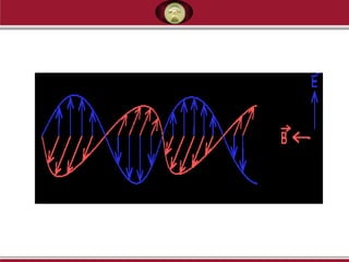
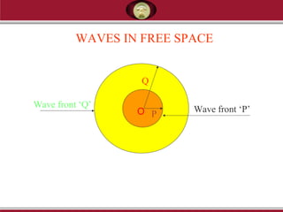
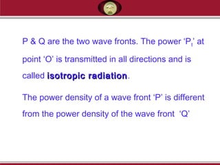
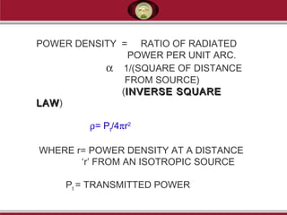
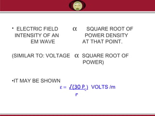
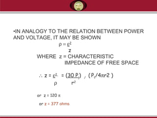
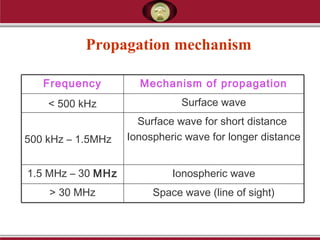
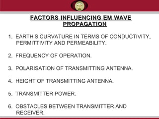
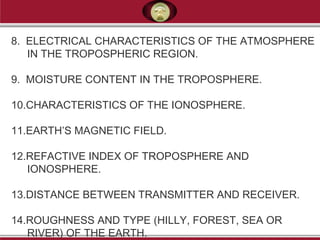
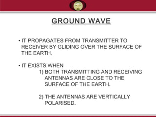
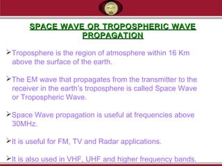
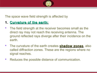
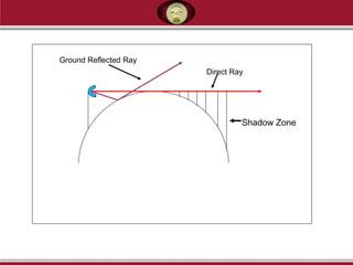
This document discusses electromagnetic waves and their propagation. It begins by defining electromagnetic waves and their properties such as being transverse waves that propagate through free space at the speed of light. It then discusses how EM waves spread uniformly in all directions from a point source, forming spherical wavefronts. The document goes on to describe different types of EM wave propagation including ground waves, space waves, and sky waves that propagate via reflection off the ionosphere. Key factors that influence EM wave propagation like frequency, transmitter power, and atmospheric conditions are also summarized.
An antenna converts radio frequency electric current into electromagnetic waves that are radiated into space. The same antenna can transmit and receive signals. Key antenna concepts include reciprocity, radiation patterns, gain, and polarization. Antenna gain compares its power output to an isotropic antenna. Common antennas include dipole, parabolic reflective, and types are optimized for propagation modes like ground wave, sky wave, and line-of-sight. Signal strength is reduced by factors like free space loss, noise, multipath, and fading over the transmission path.
The document defines and describes various parameters of antennas including beam efficiency, bandwidth, polarization, input impedance, radiation efficiency, vector effective length, equivalent areas, directivity, the Friis transmission equation, radar range equation, and antenna temperature. It provides technical details on how each parameter is defined and calculated and discusses concepts like polarization types, antenna equivalent circuits, and relationships between maximum directivity and effective area.
This document discusses aperture antennas. It begins by defining an aperture antenna as an antenna that uses an opening or closed surface as the radiating element. It then lists the main types of aperture antennas like horn antennas, reflector antennas, slot antennas, and microstrip antennas. The document focuses on analyzing aperture antennas using techniques like the current distribution method, aperture analysis, and the Fourier transform method. It explains key principles used in aperture analysis like the field equivalence principle, Huygens' principle, and Babinet's principle. The document provides examples of analyzing specific aperture antenna types and their radiation patterns.
S-parameters are a useful method for representing a circuit as a "black box" whose external behavior can be predicted without knowledge of its internal contents. S-parameters are measured by sending a signal into the black box and detecting the waves that exit each port. They depend on the network, source and load impedances, and measurement frequency. Common S-parameters include S11 for the reflected signal at port 1 and S21 for the signal exiting port 2 due to a signal entering port 1.
An antenna converts electric power into radio waves and vice versa. There are two main categories of antennas - omnidirectional antennas that radiate in all directions, and directional antennas that preferentially radiate in a particular direction. Key parameters that define antennas include frequency, directivity, efficiency, gain, wavelength, and polarization. Common types of antennas discussed are Yagi antennas, log-periodic antennas, horn antennas, loop antennas, and parabolic antennas.
Sky wave propagation involves radio waves reflecting off ionized layers in the upper atmosphere, called the ionosphere, between 50-400km above the Earth's surface. This allows radio signals to travel beyond the horizon over very long distances of thousands of kilometers. The ionosphere is divided into D, E, and F layers based on ionization density, with the F layers primarily responsible for radio wave refraction. Sky wave propagation has enabled long-distance shortwave radio communication between 3-30MHz and amateur radio communication over long distances.
A communication satellite receives radio signals from earth stations, amplifies them, and redirects them back to earth. It acts as a radio relay in space, allowing signals to be transmitted over greater distances than would be possible with terrestrial communication methods alone. A satellite's transponder receives uplink signals, amplifies them using a low-noise amplifier, down converts the frequency, filters it, amplifies it again using a power amplifier, and retransmits it back to earth on the downlink frequency. This allows the satellite to receive and redirect communications between various earth stations.
The document discusses various topics related to radio wave propagation. It covers the different types of propagation including ground wave, space wave, and sky wave. It describes line of sight propagation and how increasing antenna height allows communication over longer distances. Tropospheric propagation is discussed along with how turbulence in the troposphere can scatter radio waves. The document also covers polarization of radio waves for different propagation types and the advantages of horizontal and vertical polarization. Finally, it defines attenuation and provides examples of attenuation levels through common materials.
Ground wave propagation, Sky wave propagation, Space Wave propagation, Multi hop propagation, Duct wave propagation, LOS propagation, Ionospheric Layers
Space wave propagation involves radio waves that travel directly or after reflecting off the Earth's surface within the lower 20 km of the atmosphere. These waves can propagate line-of-sight between transmitter and receiver antennas in the VHF and UHF bands. Space waves follow two paths - direct or ground reflected - and may arrive in or out of phase, causing signal fluctuations. The maximum transmission distance is limited by the Earth's curvature and obstructions that can cause shadowing effects. Refractive phenomena like super-refraction can sometimes extend the radio horizon.
This document defines and describes parabolic antennas. It discusses the key components of a parabolic antenna including the focus, vertex, focal length, and aperture. It then explains how parabolic and hyperbolic reflectors work to direct radio waves. The document outlines different types of parabolic antennas and their applications. Parabolic antennas are commonly used for point-to-point communication, microwave relay links, wireless networks, satellite communication, radio telescopes, and radar due to their high directivity and gain.
The document provides an overview of antennas, including their history and uses. It discusses the basics of how dipole antennas work to transmit and receive electromagnetic signals. Specifically, it explains that a dipole antenna was developed in 1886 and works by efficiently radiating radio waves into space using electric and magnetic fields. It also describes different types of dipole antennas like short dipoles, quarter-wave antennas, and half-wave antennas, and how their length relates to the transmitted wavelength.
This document discusses different types of antennas used for transmitting and receiving electromagnetic waves. It describes log-periodic antennas, which work over a wide frequency range using a logarithmic size progression of elements. Specific types are described, including bow-tie antennas and log-periodic dipole arrays. Wire antennas like dipoles, monopoles, and loops are also covered. Travelling wave antennas transmit signals along their length, represented by helical and Yagi-Uda antennas. Microwave antennas and reflector antennas are used at higher frequencies for applications like communication and radar. Key antenna properties and a variety of applications are also summarized.
The document discusses key concepts related to antennas and electromagnetic waves. It defines that radio waves have electric and magnetic fields that are perpendicular to each other and the direction of wave propagation. It also describes how antennas can transmit electromagnetic waves by converting electrical energy to radio waves and receive waves by converting radio waves back to electrical energy. Antenna size is inversely proportional to frequency, with higher frequencies requiring smaller antennas. Antenna radiation patterns and near/far field regions are also discussed.
Antennas are electrical devices that convert electric currents into radio waves and vice versa. They are necessary for radio transmitters and receivers to couple to electromagnetic fields and communicate over the air. There are several types of antennas that find use in various applications like radio, television, wireless networks, and satellites. The key types discussed are isotropic antennas, half-wave dipole antennas, folded dipole antennas, omni-directional antennas, directional antennas, Yagi antennas, and sectorized antennas. Antenna selection depends on factors such as the available space, frequency of operation, power requirements, and cost.
Microwave antennas can take several forms. Horn antennas are popular and can achieve gains up to 25 dB, with directional patterns. Parabolic antennas, like satellite dishes, typically have very high gain between 30-40 dB and low cross polarization. Slot antennas are often used instead of line antennas for greater pattern control and are found in radar and cell antennas. Dipole antennas are half wave resonant conductors that radiate omnidirectionally at right angles to their axis. Their gain is approximately 2 dBi. Dielectric antennas use a traveling surface wave along a dielectric rod to radiate maximally along the rod axis.
Propagation Effects and Their Impact on Satellite-Earth Links: Introduction,
Quantifying attenuation and depolarization,
Propagation effects that are not associated with hydrometeors, Prediction of rain attenuation,
Prediction of XPD,
Propagation impairments countermeasures.
This document discusses key concepts related to antennas including:
1. It defines radiation power density as the power radiated per unit surface area from the antenna surface.
2. It explains that directivity is a measure of the directional properties of an antenna and is defined as the ratio of radiation intensity in a given direction compared to an isotropic source.
3. Gain accounts for both the directional properties and efficiency of an antenna, defined as the ratio of intensity in a given direction compared to an isotropic source radiating the same total power.
4. Additional concepts covered include beamwidth, radiation patterns, and parameters related to receiving performance such as effective length and capture area.
Ground waves propagate along the Earth's surface and are used for medium wave (MW) transmissions. Space waves travel in straight lines but are limited by the curvature of the Earth. Sky waves are used for short wave (SW) transmissions and reflect off the ionosphere which consists of layers (D, E, F1, F2) that vary in density and thickness depending on the time of day and sun exposure. Different propagation modes are used depending on the frequency band and conditions to maximize transmission range.
Satellite Link Design:
EIRP, Transmission Losses, Free-space transmission, System noise temperature and G/T ratio, Noise figure, Design of downlinks, Design of uplink, Design of specified C/N: combining C/N and C/I values in satellite links, Overall C/No, Link design procedure.
This document discusses different types of traveling wave antennas, including long wire antennas and V antennas. It provides definitions of traveling wave antennas as non-resonant antennas where standing waves do not exist along the length. Long wire antennas are classified as having a length between 1-many wavelengths. Their current distribution attenuates along the length due to losses. V antennas consist of two wire antennas arranged horizontally to form a V shape. They can be resonant or non-resonant. Rhombic antennas are formed from two connected V antennas in a diamond shape and are highly directional but require large spaces. The document provides examples of their usage and concludes with designing a rhombic antenna.
Ultra-wideband (UWB) antennas must transmit very short pulse signals accurately and efficiently. The document discusses various types of UWB antennas including traveling-wave antennas like horn antennas, frequency-independent antennas whose radiation patterns do not change with frequency, self-complementary antennas with constant input impedance regardless of frequency or shape, multiple resonance antennas made of multiple narrowband elements, and electrically small antennas. Key antenna characterization parameters in time and frequency domains are also presented.
This document summarizes the helical antenna. The helical antenna is a broadband VHF and UHF antenna that provides circular polarization. It consists of a helix of thick copper wire wound in a screw thread shape around a metal plate ground plane. The helix is fed by a coaxial cable connected to the inner conductor, while the outer conductor connects to the ground plane. The antenna can operate in two modes - normal mode and axial mode - depending on the helix diameter, turn spacing, and other dimensions. The normal mode radiates perpendicularly to the axis for circular polarization. The axial ratio and other parameters must meet certain conditions for effective circular polarization.
This document discusses transmission lines and their key characteristics. It begins by defining a transmission line as a medium that directs the transmission of energy, such as electromagnetic waves, from one place to another. Transmission lines are designed to carry alternating current and have a more specific meaning in communications and electronics where their wave nature must be accounted for. The document then discusses some key aspects of transmission line operation, including that voltage and current are functions of both time and position along the line. It provides examples of common transmission line structures and discusses transmission line equivalent circuits and relevant equations for modeling transmission line behavior.
Radio waves can propagate from the transmitter to the receiver via three main ways: ground waves, sky waves, and space waves. Ground waves travel along the earth's surface for short-range communication. Sky waves travel upward and reflect off ionized layers in the ionosphere to allow long-range communication. Space waves travel directly through the air but are affected by factors like atmospheric conditions, earth curvature, and heights of transmitting and receiving antennas. The distance radio waves can propagate depends on the transmission method used and various environmental factors.
Radio waves can propagate between two points through four main ways: directly, following the curvature of the Earth, becoming trapped in the atmosphere, or refracting off the ionosphere. Propagation modes include ground-wave, sky-wave, and space-wave propagation. Mobile radio propagation is influenced by factors like reflections, scattering, diffraction, and the electromagnetic properties of materials. Proper propagation modeling is important for wireless system design and performance.
The document discusses electromagnetic waves and their properties. Some key points:
1) Electromagnetic waves consist of oscillating electric and magnetic fields perpendicular to each other and perpendicular to the direction of wave propagation.
2) Both the electric and magnetic fields of an electromagnetic wave are transverse to the direction of wave propagation.
3) Electromagnetic waves include radio waves, microwaves, infrared, visible light, ultraviolet, X-rays, and gamma rays. They differ in wavelength and frequency.
01_AME_U1_INTRODUCTION AND MICROWAVE FREQUENCY BANDS.pptxMrEmmanuelA
UNIT I introduces microwave systems and antennas. It discusses microwave frequency bands from 1 GHz to 300 GHz and key antenna concepts like near and far fields, gain, efficiency, impedance matching, and the Friis transmission equation. The unit also covers antenna pattern characteristics, radiated power and fields, and antenna noise temperature.
UNIT I provides an overview of key topics in microwave engineering and antenna fundamentals, including microwave frequency bands, antenna radiation mechanisms, near and far-field regions, antenna parameters like gain and pattern characteristics, impedance matching concepts, and noise modeling of microwave systems.
This document discusses EMI/EMC, including various sources of electromagnetic interference and transients that can affect electronic systems, such as crosstalk between transmission lines, switching transients, and lightning strikes. It also covers open area test sites and measurements for evaluating radiated emissions and susceptibility of equipment to electromagnetic fields. Key points include the importance of minimizing scattering at test sites, and using antennas and measurement precautions appropriately based on frequency ranges and standards.
This document discusses the history and development of radar technology. It begins with early experiments with radio waves in the late 1800s by scientists like Hertz, Hulsmeyer and Tesla. It then outlines key developments in radar including the first demonstration of detecting aircraft using radio echoes in 1935 by Watson-Watt and Wilkins. The document also discusses the basic components and operating principles of radar systems including antennas, transmitters, receivers and data processors. It provides examples of converting between decimal, binary, octal and hexadecimal number systems.
Microwave frequency bands range from 1 GHz to 1000 GHz with wavelengths between 30 cm and 0.03 cm. They are used in both military and civilian applications. An antenna is an electrical conductor that transmits electromagnetic energy into space from a transmission line and receives electromagnetic energy from space to induce currents in a receiver. Antennas work by coupling electromagnetic waves between guided transmission line waves and free space waves.
Radar is a system that uses radio waves to determine the range, altitude, direction, or speed of objects. It works by transmitting pulses of radio waves that bounce off objects and return to the receiver dish. The document discusses the history, principles, applications, and components of radar systems. It originated in the late 19th century and was developed for military use in the early 20th century to detect aircraft and ships. Radar is now widely used for weather monitoring, air traffic control, marine navigation, speed enforcement, and other applications.
This document discusses line-of-sight (LOS) radio propagation. It defines LOS propagation as occurring when frequencies are above 30 MHz, where signals travel in straight lines between antennas without being reflected by the ionosphere. It describes how the maximum distance of LOS propagation, known as the radio horizon, is determined by the curvature of the Earth and the heights of the transmitting and receiving antennas. It also discusses factors that can impair LOS wireless transmission, such as free space loss, scattering, atmospheric absorption, ducting, refraction, reflection, and shadowing effects.
Chap 02 antenna & wave propagation EngkaderAMuse
This document summarizes key concepts about antennas and wireless signal propagation. It discusses different types of antennas like dipole antennas and parabolic reflective antennas. It also describes the main modes of wireless signal propagation including ground-wave propagation, sky-wave propagation, and line-of-sight propagation. Additionally, it outlines several factors that can impair wireless signals during propagation, such as attenuation, noise, multipath, and atmospheric absorption.
Antenna Types and their impact on the comn sys.pptxSudhakarTyagi2
- Antennas come in different types based on frequency range, operating range, mode of application, and physical structure. Common types include wire antennas, slot/aperture antennas, reflector/lens antennas, and microstrip antennas.
- Key antenna parameters that impact communication systems include radiation pattern, impedance, bandwidth, gain, efficiency, directivity, and polarization. Proper impedance matching between the antenna and transmission line is important for maximum power transfer. A high gain antenna directs radiation more effectively in a desired direction.
1) Offset refers to the horizontal distance between a seismic source and receiver. It causes a delay in the arrival time of reflections that can be corrected before stacking seismic traces.
2) Acoustic impedance is the product of density and seismic velocity, which varies between rock layers and affects the reflection coefficient at layer boundaries.
3) A seismogram contains traces recorded from a single shot point, and multiple seismograms make up a seismic section.
A waveguide is a hollow metallic tube that transmits electromagnetic waves through successive reflections off the inner walls. There are two common modes of propagation in a waveguide: transverse magnetic (TM) and transverse electric (TE). Waveguides come in different shapes including rectangular, circular, elliptical, single ridged, and double ridged. Microwaves propagate through waveguides in distinct field patterns called modes of propagation such as TEM, TE, TM, and HE. Important waveguide parameters include cut-off wavelength, group velocity, phase velocity, and wave impedance.
Explaining all the difficult concepts with precise and accurate points, 3D models, animations and smart art graphics.
Principle
The NMR phenomenon
Theory
Precessional frequency (ν)
Chemical shift
Spin-spin interactions
Interpretation of NMR
Chemical shift (δ)
Multiplicity of the signal
Coupling constant
Instrumentation
Fourier NMR
Continuous wave NMR
Applications
Identification testing
Assay of drugs
Radio waves are electromagnetic waves that propagate through free space as transverse electromagnetic waves, with the electric field, magnetic field, and direction of propagation being mutually perpendicular. When emitted by an antenna, radio waves travel through space and are affected by objects they encounter, with the signal strength decreasing with distance from the transmitter due to the inverse square law. Radio waves can be reflected, refracted, diffracted, and focused similar to light waves.
This document discusses radio wave propagation. It begins by revisiting transverse electromagnetic waves and their properties. It then discusses different parameters of radio waves like frequency, wavelength, polarization, and intrinsic impedance. It describes various modes of propagation including ground waves, sky waves, and space waves. Ground waves travel along the Earth's surface up to 2 MHz. Sky waves are reflected by the ionosphere to propagate over longer distances on HF bands. Space waves use line-of-sight propagation on VHF and UHF bands. The document also reviews optical properties like reflection, diffraction and interference experienced by radio waves.
This document discusses physical modeling of wireless channels. It covers:
1) Large-scale and small-scale fading effects that cause variations in channel strength over time and frequency. Small-scale fading is more relevant for communication system design.
2) Models for free space propagation with fixed and moving antennas. A moving receiver experiences Doppler shift that changes the received frequency.
3) A model with a single reflecting wall, where the direct and reflected signals interfere constructively or destructively depending on their path length difference. This causes multipath fading for a moving receiver.
Radio Frequency Waves ,Data communication & Networkssameer farooq
Radio waves are electromagnetic waves that propagate through free space. They have a wavelength between 1mm and 30km and a frequency between 10KHz and 300GHz. Information such as sound and images can be transmitted using radio waves by modifying properties of the wave like its amplitude or frequency. Radio waves can propagate through different modes including ground waves, sky waves, and line-of-sight. Various factors can impair radio wave transmission over long distances including attenuation, noise, multipath propagation, and refraction in the atmosphere. Radio waves are generated by oscillating electric and magnetic fields produced by accelerating charges and can encode both analog and digital information.
The 8085 microprocessor was introduced by Intel in 1976 as an updated version of the 8080 microprocessor. It is an 8-bit microprocessor that can access 64KB of memory using 16-bit address lines and has 8 I/O ports. It contains registers like the accumulator, flag register, and instruction register. The 8085 has an arithmetic logic unit and uses various addressing modes like immediate, register, direct, indirect and implied addressing. It consists of functional blocks like registers, instruction decoder, address/data buffers, and interrupt control.
The document discusses microprocessors, their architecture, instructions, operations, interfacing and the 8085 and 8086 microprocessors. It provides details on the functional blocks, registers, addressing modes, procedures, calling conventions, and stack usage of the 8086 microprocessor. It also describes various assembler directives, operators, and concepts like logical segments, procedures, and passing parameters in registers vs memory for procedures.
The 8085 microprocessor is an 8-bit microprocessor introduced in 1976 as an updated version of the 8080. It has features like multiplexed address/data bus and interrupt pins. The 8085 consists of units like the accumulator, ALU, registers, program counter, stack pointer, flags, and instruction decoder. It uses flags to indicate arithmetic results and has interrupt controls. Registers are used for data, addressing, and instructions. The timing and control unit coordinates operations using a clock. Serial I/O is also supported.
The document describes the implementation of a 16-bit microprocessor core called "MIB-16" using VHDL. It discusses designing the various components of the microprocessor like the ALU, control unit, registers etc. separately in VHDL, simulating them and then implementing the entire design on an FPGA. The microprocessor can access 64KB of memory and execute instructions like addition, subtraction etc. VHDL allows for modeling digital systems at different levels of abstraction and the microprocessor design demonstrates its use for designing an entire processor.
Bharat Electronics Limited (BEL) is an Indian government-owned electronics company headquartered in Bengaluru, India. It was established in 1954 and is owned by the Indian government. BEL primarily manufactures advanced electronics products for the Indian armed forces and has 9 factories across India. It has a vision to be a world-class enterprise in professional electronics and a mission to be a customer-focused and globally competitive company in defense electronics. BEL designs and develops products in fields like telecommunications, radars, missiles, electronic warfare systems, and more. As of April 2012, BEL's order book was estimated at around 25,748 crore (US$4.87 billion). Mr. Anil Kumar
This document provides an overview of Pramod Kumar Dwivedi's summer training at Bharat Electronics Limited (BEL). It discusses BEL's history as a public sector company established in 1954. It describes BEL's manufacturing units across India and its main product lines which include radar, x-ray tubes, and broadcast equipment. The document outlines Pramod's rotation program and provides details about radar technology, including its basic principle of transmitting and receiving electromagnetic signals to detect objects, the radar range equation, components of a radar system, and factors that affect radar beams such as attenuation and reflection.
This document provides information about Bharat Electronics Limited (BEL), an Indian public sector undertaking. It discusses BEL's establishment, manufacturing units, product ranges including radar systems and communications equipment. Specific details are given about the Ghaziabad unit, its departments under rotation program like testing equipment automation and magnetics lab. An introduction to radar technology is provided along with the basic radar system and equation. The document focuses on BEL's SRE radar project, describing the radar electronic cabinet and briefly outlining the radar subsystem and its applications.
Bharat Electronics Limited (BEL) is a state-owned electronics company headquartered in Bengaluru, India. It was incorporated in 1954 and manufactures advanced electronic products for the Indian Armed Forces. BEL has over 11,000 employees and annual revenues of over $1 billion. It operates 9 factories across India and has diversified into areas like telecom, broadcasting, radar systems, and electronic voting machines. BEL plays a key role in India's defense sector by manufacturing products like tank simulators, wireless equipment, radars, and other electronic systems.
Bharat Electronics Limited (BEL) is an Indian state-owned electronics and telecommunications company headquartered in Bangalore. It was established in 1954 by the Government of India to meet the specialized electronics needs of the Indian defense services. Over the years, BEL has expanded into a multi-product, multi-technology conglomerate company with nine manufacturing units across India. It primarily manufactures advanced electronic products for Indian defense forces such as radars, naval systems, telecommunication equipment, and other products for civilian use like electronic voting machines and solar products. The document provides details about BEL's history, manufacturing units, products, quality control processes, and the rotational training program undergone by the author in different departments like
Bharat Electronics Limited (BEL) is an Indian state-owned aerospace and defense company headquartered in Bangalore. It was established in 1954 and has nine manufacturing units located across India. BEL manufactures advanced electronics and communication equipment for the Indian Armed Forces and Indian Space Research Organisation. It has a strong R&D base and manufactures products like radars, naval systems, electronic voting machines, and telecom equipment. BEL aims to be a globally competitive company in defense electronics and other fields through in-house R&D and strategic partnerships.
The document provides an overview of Bharat Electronics Limited (BEL) and its Kotdwara unit. Some key points:
- BEL is an Indian public sector undertaking under the Ministry of Defense manufacturing electronic products. It has 9 manufacturing units across India.
- The Kotdwara unit was established in 1985 and manufactures products like telecom switching equipment, radios, fire detection systems and more.
- The document outlines the unit's mission, organization structure, major milestones, product portfolio, and describes departments like HR, marketing, production, and finance.
- It also provides details on quality initiatives, employee development programs, and marketing and sales processes at the Kotdwara unit.
The document discusses the basics of light emitting diodes (LEDs) and liquid crystal displays (LCDs). It provides information on how LEDs and LCDs work, including:
- LEDs emit light when electrons recombine with positive charges in the semiconductor chip. LCDs use the optical properties of liquid crystals and polarized light to display images.
- Key components of LEDs include the semiconductor chip and current-limiting resistors. LCDs have layers of liquid crystals between two polarized filters that can be manipulated by electric fields to allow light to pass through or not.
- Performance factors for LEDs and LCDs include color, intensity, operating life, and voltage/current requirements. Advantages over other
This document covers the basics of electronics including semiconductor theory, diodes, transistors, and digital circuits. It discusses how doping semiconductors like silicon creates N-type and P-type materials. A diode is formed from a PN junction, which allows current to flow easily in one direction. Transistors use two back-to-back diodes to control current flow. Digital circuits represent information using binary numbers of 0s and 1s implemented with logic gates and basic digital components.
The document discusses computer fundamentals including defining computers and their uses. It describes the main types of computers as microcomputers, minicomputers, mainframes, and supercomputers. The basic structure of a computer is also outlined including input, output, storage, and processing devices. Finally, the internal components of a personal computer like the CPU, motherboard, RAM, storage, and power supply are identified.
This document provides an introduction to basic electronics concepts. It explains that basic electronics comprises the minimal electronic components that make up everyday electronics, including resistors, capacitors, and diodes. It describes how all electronics work according to Ohm's Law, which states that voltage is directly proportional to current and resistance. The document also defines key electronics terms like circuits, voltage, current, resistors, capacitors, and power. It provides examples of calculating total resistance in series and parallel circuits.
This document provides an overview of basic electronics components and circuits. It begins with an introduction to passive components like resistors, capacitors, inductors, and transformers. It then covers analog circuits using transistors and operational amplifiers. The document provides details on circuit analysis and different types of filters. It explains concepts like resistors, capacitors, inductors, diodes, transistors, and operational amplifiers. Examples of common circuits are also presented like voltage dividers, rectifiers, and amplifiers.
The document provides an overview of basic electrical and electronics concepts and components. It begins with definitions of key terms like electricity, voltage, current and atomic structure. It then explains components like resistors, capacitors, diodes, transistors and how they work. Different circuit applications using these components are discussed, including rectifiers, amplifiers and oscillators. The document serves as training material for an introductory workshop on circuit design and analysis.
This document discusses the various applications of electronics components. It describes how sophistication in miniaturization has allowed single integrated circuits to perform hundreds of operations using only a few watts of power. It also outlines some basic development tools like breadboards and multimeters used in electronics. Furthermore, it provides details on common electronic components like resistors, capacitors, diodes, transistors, integrated circuits and sensors; describing their applications in areas like communications, automation, defense and more.
This document provides an overview of basic electronics theory. It defines electronics as the branch of physics dealing with electrons and electronic devices. It describes the three states of matter and how atoms are made up of protons, neutrons, and electrons. Kirchhoff's laws are introduced regarding the behavior of electric charges. Conductors, insulators, voltage, current, and resistance are defined. The document also covers basic circuit diagrams, Ohm's law, capacitors, and different types of capacitors.
The document provides an overview of microwave engineering and rectangular waveguides. It defines microwave frequencies as ranging from 1 GHz to 300 GHz. Rectangular waveguides transmit electromagnetic waves through successive reflections from inner walls. Modes in waveguides include transverse electric (TE) and transverse magnetic (TM) modes. The document analyzes the TM and TE modes in rectangular waveguides through solving Maxwell's equations with boundary conditions. Cut-off frequencies above which modes can propagate are determined. Examples demonstrate calculating waveguide parameters and resonant frequencies of cavity resonators.
Discover the latest insights on Data Driven Maintenance with our comprehensive webinar presentation. Learn about traditional maintenance challenges, the right approach to utilizing data, and the benefits of adopting a Data Driven Maintenance strategy. Explore real-world examples, industry best practices, and innovative solutions like FMECA and the D3M model. This presentation, led by expert Jules Oudmans, is essential for asset owners looking to optimize their maintenance processes and leverage digital technologies for improved efficiency and performance. Download now to stay ahead in the evolving maintenance landscape.
DEEP LEARNING FOR SMART GRID INTRUSION DETECTION: A HYBRID CNN-LSTM-BASED MODELijaia
As digital technology becomes more deeply embedded in power systems, protecting the communication
networks of Smart Grids (SG) has emerged as a critical concern. Distributed Network Protocol 3 (DNP3)
represents a multi-tiered application layer protocol extensively utilized in Supervisory Control and Data
Acquisition (SCADA)-based smart grids to facilitate real-time data gathering and control functionalities.
Robust Intrusion Detection Systems (IDS) are necessary for early threat detection and mitigation because
of the interconnection of these networks, which makes them vulnerable to a variety of cyberattacks. To
solve this issue, this paper develops a hybrid Deep Learning (DL) model specifically designed for intrusion
detection in smart grids. The proposed approach is a combination of the Convolutional Neural Network
(CNN) and the Long-Short-Term Memory algorithms (LSTM). We employed a recent intrusion detection
dataset (DNP3), which focuses on unauthorized commands and Denial of Service (DoS) cyberattacks, to
train and test our model. The results of our experiments show that our CNN-LSTM method is much better
at finding smart grid intrusions than other deep learning algorithms used for classification. In addition,
our proposed approach improves accuracy, precision, recall, and F1 score, achieving a high detection
accuracy rate of 99.50%.
Gas agency management system project report.pdfKamal Acharya
The project entitled "Gas Agency" is done to make the manual process easier by making it a computerized system for billing and maintaining stock. The Gas Agencies get the order request through phone calls or by personal from their customers and deliver the gas cylinders to their address based on their demand and previous delivery date. This process is made computerized and the customer's name, address and stock details are stored in a database. Based on this the billing for a customer is made simple and easier, since a customer order for gas can be accepted only after completing a certain period from the previous delivery. This can be calculated and billed easily through this. There are two types of delivery like domestic purpose use delivery and commercial purpose use delivery. The bill rate and capacity differs for both. This can be easily maintained and charged accordingly.
Prediction of Electrical Energy Efficiency Using Information on Consumer's Ac...PriyankaKilaniya
Energy efficiency has been important since the latter part of the last century. The main object of this survey is to determine the energy efficiency knowledge among consumers. Two separate districts in Bangladesh are selected to conduct the survey on households and showrooms about the energy and seller also. The survey uses the data to find some regression equations from which it is easy to predict energy efficiency knowledge. The data is analyzed and calculated based on five important criteria. The initial target was to find some factors that help predict a person's energy efficiency knowledge. From the survey, it is found that the energy efficiency awareness among the people of our country is very low. Relationships between household energy use behaviors are estimated using a unique dataset of about 40 households and 20 showrooms in Bangladesh's Chapainawabganj and Bagerhat districts. Knowledge of energy consumption and energy efficiency technology options is found to be associated with household use of energy conservation practices. Household characteristics also influence household energy use behavior. Younger household cohorts are more likely to adopt energy-efficient technologies and energy conservation practices and place primary importance on energy saving for environmental reasons. Education also influences attitudes toward energy conservation in Bangladesh. Low-education households indicate they primarily save electricity for the environment while high-education households indicate they are motivated by environmental concerns.
Design and optimization of ion propulsion dronebjmsejournal
Electric propulsion technology is widely used in many kinds of vehicles in recent years, and aircrafts are no exception. Technically, UAVs are electrically propelled but tend to produce a significant amount of noise and vibrations. Ion propulsion technology for drones is a potential solution to this problem. Ion propulsion technology is proven to be feasible in the earth’s atmosphere. The study presented in this article shows the design of EHD thrusters and power supply for ion propulsion drones along with performance optimization of high-voltage power supply for endurance in earth’s atmosphere.
Applications of artificial Intelligence in Mechanical Engineering.pdfAtif Razi
Historically, mechanical engineering has relied heavily on human expertise and empirical methods to solve complex problems. With the introduction of computer-aided design (CAD) and finite element analysis (FEA), the field took its first steps towards digitization. These tools allowed engineers to simulate and analyze mechanical systems with greater accuracy and efficiency. However, the sheer volume of data generated by modern engineering systems and the increasing complexity of these systems have necessitated more advanced analytical tools, paving the way for AI.
AI offers the capability to process vast amounts of data, identify patterns, and make predictions with a level of speed and accuracy unattainable by traditional methods. This has profound implications for mechanical engineering, enabling more efficient design processes, predictive maintenance strategies, and optimized manufacturing operations. AI-driven tools can learn from historical data, adapt to new information, and continuously improve their performance, making them invaluable in tackling the multifaceted challenges of modern mechanical engineering.
Optimizing Gradle Builds - Gradle DPE Tour Berlin 2024Sinan KOZAK
Sinan from the Delivery Hero mobile infrastructure engineering team shares a deep dive into performance acceleration with Gradle build cache optimizations. Sinan shares their journey into solving complex build-cache problems that affect Gradle builds. By understanding the challenges and solutions found in our journey, we aim to demonstrate the possibilities for faster builds. The case study reveals how overlapping outputs and cache misconfigurations led to significant increases in build times, especially as the project scaled up with numerous modules using Paparazzi tests. The journey from diagnosing to defeating cache issues offers invaluable lessons on maintaining cache integrity without sacrificing functionality.
Supermarket Management System Project Report.pdfKamal Acharya
Supermarket management is a stand-alone J2EE using Eclipse Juno program.
This project contains all the necessary required information about maintaining
the supermarket billing system.
The core idea of this project to minimize the paper work and centralize the
data. Here all the communication is taken in secure manner. That is, in this
application the information will be stored in client itself. For further security the
data base is stored in the back-end oracle and so no intruders can access it.
Build the Next Generation of Apps with the Einstein 1 Platform.
Rejoignez Philippe Ozil pour une session de workshops qui vous guidera à travers les détails de la plateforme Einstein 1, l'importance des données pour la création d'applications d'intelligence artificielle et les différents outils et technologies que Salesforce propose pour vous apporter tous les bénéfices de l'IA.
Digital Twins Computer Networking Paper Presentation.pptxaryanpankaj78
A Digital Twin in computer networking is a virtual representation of a physical network, used to simulate, analyze, and optimize network performance and reliability. It leverages real-time data to enhance network management, predict issues, and improve decision-making processes.
3. ELECTROMAGNETIC WAVESELECTROMAGNETIC WAVES
• A WAVE IS A CARRIER OF ENERGY OR INFORMATION,
WHICH IS A FUNCTION OF TIME AND SPACE.
• MAXWELL PREDICTED THE EXISTENCE OF EM WAVES
AND ESTABLISHED IT THROUGH MAXWELL'S
EQUATION.
• EXAMPLES : RADIO, RADAR BEAMS, TV SIGNALS etc.
4. ELECTROMAGNETIC WAVESELECTROMAGNETIC WAVES
•OSCILLATIONS WHICH PROPAGATEPROPAGATE THROUGH FREE
SPACE WITH THE VELOCITY OF LIGHTWITH THE VELOCITY OF LIGHT (i.e.3x108
m/s)
•THESE ARE TRANSVERSE WAVESTRANSVERSE WAVES (OSCILLATIONS
PERPENDICULAR TO DIRECTION OF PROPAGATION)
•IT HAS ELECTRIC FIELD AND MAGNETIC FIELD WHICH
ARE HENCE PERPENDICULAR TO DIRECTION OF
PROPAGATION AND ALSO MUTUALLYMUTUALLY
PERPENDICULARPERPENDICULAR.
5.
6. EM WAVES SPREAD UNIFORMLYSPREAD UNIFORMLY IN ALL
DIRECTIONS IN FREE SPACE FROM A POINT
SOURCE.
THE PLANE JOINING ALL THE POINTS OF
IDENTICAL PHASE AT A PARTICULAR INSTANT
IS CALLED A WAVE FRONTWAVE FRONT.
IN FREE SPACE, IT IS SPHERICALSPHERICAL.
8. ELECTROMAGNETIC RADIATIONELECTROMAGNETIC RADIATION
POWER ESCAPING INTO SPACE IS SAID TO BE
RADIATED & IS GOVERNED BY THE
CHARACTERISTICS OF FREE SPACE.
FREE SPACEFREE SPACE
SPACE THAT DOES NOT INTERFEREDOES NOT INTERFERE WITH THE
NORMAL RADIATION & PROPAGATION OF RADIO
WAVES.
IT DOES NOT HAVE MAGNETIC OR GRAVITATIONAL
FIELDS, SOLID BODIES OR IONISED PARTICLES.
9. •ISOTROPIC SOURCEISOTROPIC SOURCE :- WHICH RADIATESRADIATES
EQUALLYEQUALLY IN ALL DIRECTIONS IN SPACE.
•ISOTROPIC MEDIUMISOTROPIC MEDIUM :- IN WHICH VELOCITY OFVELOCITY OF
RADIATION IS CONSTANTRADIATION IS CONSTANT AT ALL POINTS (AS IN
FREE SPACE). THIS MAKES THE WAVE FRONT
SPHERICAL.
12. P & Q are the two wave fronts. The power ‘Pt’ at
point ‘O’ is transmitted in all directions and is
called isotropic radiationisotropic radiation.
The power density of a wave front ‘P’ is different
from the power density of the wave front ‘Q’
13. POWER DENSITY = RATIO OF RADIATED
POWER PER UNIT ARC.
α 1/(SQUARE OF DISTANCE
FROM SOURCE)
(INVERSE SQUAREINVERSE SQUARE
LAWLAW)
ρ= Pt/4πr2
WHERE r= POWER DENSITY AT A DISTANCE
‘r’ FROM AN ISOTROPIC SOURCE
Pt = TRANSMITTED POWER
14. • ELECTRIC FIELD α SQUARE ROOT OF
INTENSITY OF AN POWER DENSITY
EM WAVE AT THAT POINT.
(SIMILAR TO: VOLTAGE α SQUARE ROOT OF
POWER)
•IT MAY BE SHOWN
ε = √(30 Pt
) VOLTS /m
r
15. •IN ANALOGY TO THE RELATION BETWEEN POWER
AND VOLTAGE, IT MAY BE SHOWN
ρ = ε2
z
WHERE z = CHARACTERISTIC
IMPEDANCE OF FREE SPACE
∴ z = ε2
= (30 Pt
) /
( Pt/4πr2 )
ρ r2
or z = 120 π
or z = 377 ohms
16. APPLICATIONSAPPLICATIONS
• IN ALL COMMUNICATIONS LIKE
• POLICE RADIO TV
SATELLITE IONOSPHERIC
TROPOSPHERIC WIRELESS
CELLULAR MOBILE COMMUNICATIONS
IN ALL TYPES OF RADARS LIKE
• DOPPLER RADAR
• AIRPORT SURVEILLANCE RADAR
• WEATHER FORECASTING RADAR
• REMOTE SENSING RADAR
• GROUND MAPPING RADAR
• FIRE CONTROL RADAR
ALSO USED IN RADIO THERAPY, MW OVENS etc.
17. FREQUENCY ALLOCATIONSFREQUENCY ALLOCATIONS
HIGH FREQUENCY (HF)3 TO 30 MHZ
VERY HIGH FREQUENCY (VHF)30 TO 300 MHZ
ULTRA HIGH FREQUENCY (UHF)300 TO 3000 MHZ
SUPER HIGH FREQUENCY (SHF)3 TO 30 GHZ
VOICE FREQUENCY (VF)300 TO 3000 HZ
LOW FREQUENCY (LF)30 TO 300 KHZ
EXTREMELY LOW FREQUENCY
(ELF)
30 TO 300 HZ
MEDIUM FREQUENCY (MF)300 TO 3000 KHZ
VERY LOW FREQUENCY (VLF)3 TO 30 KHZ
EXTREMELY HIGH
FREQUENCY(EHF)
30 TO 300 GHZ
DESIGNATIONFREQUENCY
18. Propagation mechanism
Space wave (line of sight)> 30 MHz
Ionospheric wave1.5 MHz – 30 MHz
Surface wave for short distance
Ionospheric wave for longer distance500 kHz – 1.5MHz
Surface wave< 500 kHz
Mechanism of propagationFrequency
19. Radio frequency bands used in Railways
HF communication (3 MHz-30 MHz band) was once
used in Railways; Now obsolete
7 GHz MW,
18 GHz MW
3GHz – 30 GHzSHF (MW)
2 GHz UHF links,
Train radio through
leaky coaxial cable
in tunnels,
GSM & GSM-R
300 MHz – 3 GHzUHF
Walkie-talkie30 MHz – 300 MHzVHF
ApplicationBandFrequency
range
20. GSM & GSM-R
921-960 MHz876-915 MHzGSM-R
1930-1990 MHz1850-1910 MHzGSM-1900
1805-1880 MHz1710-1785 MHzGSM-1800
935-960 MHz890-915 MHzGSM-900
Down link
(BTS to MS)
Up link
(MS to BTS)
Type
22. POLARISATION OF A WAVEPOLARISATION OF A WAVE
THE POLARISATION OF A WAVE IS DEFINED AS THE
DIRECTION OF THE ELECTRIC FIELDDIRECTION OF THE ELECTRIC FIELD AT A
GIVEN POINT OF TIME
TYPES OF POLARISATION
• LINEAR POLARISATION
i) HORIZONTAL POLARISATION
ii) VERTICAL POLARISATION
iii)THETA POLARISATION
• CIRCULAR POLARISATION
• ELLIPTICAL POLARISATION
23. A WAVE IS SAID TO BE LINEARELY POLARISEDLINEARELY POLARISED
IF THE ELECTRIC FIELD LIES WHOLLY IN ONE
PLANE CONTAINING THE DIRECTION OF
PROPAGATION.
IF EY=0 AND EX IS PRESENT, WHEN A WAVE
TRAVELS IN Z-DIRECTION WITH E-FIELD LYING IN
XY-PLANE, IT IS SAID TO BE HORIZONTALLYHORIZONTALLY
POLARISEDPOLARISED.
IF EX=0 AND EY IS PRESENT, THEN THE WAVE IS
VERTICALLY POLARISEDVERTICALLY POLARISED.
IF EX AND EY ARE PRESENT AND ARE IN PHASE,
THEN THE WAVE IS THETA POLARISEDTHETA POLARISED.
24. FOR HORIZONTALLY POLARISED WAVE, THE
ELECTRIC FIELDELECTRIC FIELD LIES IN A PLANE PARALLELPARALLEL
TO EARTH’S SURFACETO EARTH’S SURFACE.
ALL THE ELECTRIC INTENSITY VECTORS ARE
VERTICAL FOR A VERTICALLY POLARISED WAVE.
THE DIRECTION OF POLARISATION IS SAMETHE DIRECTION OF POLARISATION IS SAME
AS THE DIRECTION OF ANTENNAAS THE DIRECTION OF ANTENNA.
THUS, VERTICALLY POLARISED WAVE IS RADIATED
BY VERTICAL ANTENNA.
HORIZONTALLY POLARISED WAVE IS RADIATED BY
HORIZONTAL ANTENNA.
28. PROPAGATION CHARACTERISTICS OF EMPROPAGATION CHARACTERISTICS OF EM
WAVESWAVES
• THE WAVE PROPAGATION CHARACTERISTICS
BETWEEN TRANSMITTER AND
RECEIVER ARE CONTROLLED BY
1) TRANSMITTING ANTENNA
2) OPERATING FREQUENCIES
3) MEDIA BETWEEN TX AND RX
• THE EM WAVE RADIATED BY THE TX ANTENNA
IS A TRANSVERSE WAVE.
29. IT MOVES FROM TX TO RX IN THE FOLLOWING WAYS
1. A PART OF THE WAVE TRAVELS ALONG OR NEAR
THE SURFACE OF THE EARTH. THIS IS GROUNDTHIS IS GROUND
WAVE.WAVE.
2. SOME WAVES NEITHER FOLLOWS THE EARTH, NOR
MOVES TOWARD THE SKY, BUT TRAVELS
DIRECTLY FROM THE TX TO THE RX ANTENNA.
THESE ARE SPACE OR TROPOSPHERICSPACE OR TROPOSPHERIC
WAVESWAVES.
3. SOME WAVES TRAVEL UPWARDS TOWARDS THE
SKY AND GET REFLECTED BACK TO THE
RECEIVER.
THESE ARE SKY OR IONOSPHERIC WAVESSKY OR IONOSPHERIC WAVES.
30. •GROUND WAVESGROUND WAVES ARE USEFUL FOR
COMMUNICATION AT VLF, LF & MF RANGES
(BROADCAST SIGNALS RECEIVED DURING DAY)
•SPACE WAVESSPACE WAVES ARE USEFUL ABOVE THE
FREQUENCY OF 30 MHZ
(FM RECEPTION IS NORMALLY BY SPACE WAVE
PROPAGATION)
•SKY WAVESSKY WAVES ARE USEFUL FOR FREQUENCIES
BETWEEN 3 TO 30 MHZ
(RESPONSIBLE FOR LONG DISTANCE
COMMUNICATION)
32. FACTORS INFLUENCING EM WAVEFACTORS INFLUENCING EM WAVE
PROPAGATIONPROPAGATION
1. EARTH’S CURVATURE IN TERMS OF CONDUCTIVITY,
PERMITTIVITY AND PERMEABILITY.
2. FREQUENCY OF OPERATION.
3. POLARISATION OF TRANSMITTING ANTENNA.
4. HEIGHT OF TRANSMITTING ANTENNA.
5. TRANSMITTER POWER.
6. OBSTACLES BETWEEN TRANSMITTER AND
RECEIVER.
33. 8. ELECTRICAL CHARACTERISTICS OF THE ATMOSPHERE
IN THE TROPOSPHERIC REGION.
9. MOISTURE CONTENT IN THE TROPOSPHERE.
10.CHARACTERISTICS OF THE IONOSPHERE.
11.EARTH’S MAGNETIC FIELD.
12.REFACTIVE INDEX OF TROPOSPHERE AND
IONOSPHERE.
13.DISTANCE BETWEEN TRANSMITTER AND RECEIVER.
14.ROUGHNESS AND TYPE (HILLY, FOREST, SEA OR
RIVER) OF THE EARTH.
35. GROUND WAVE
• IT PROPAGATES FROM TRANSMITTER TO
RECEIVER BY GLIDING OVER THE SURFACE OF
THE EARTH.
• IT EXISTS WHEN
1) BOTH TRANSMITTING AND RECEIVING
ANTENNAS ARE CLOSE TO THE
SURFACE OF THE EARTH.
2) THE ANTENNAS ARE VERTICALLY
POLARISED.
36. •IT IS OF IMPORTANCE AT MF (BROADCAST) AND
LF
•IT IS LIMITED TO ONLY A FEW KM.
•FIELD STRENGTH VARIES WITH
CHARACTERISTICSCHARACTERISTICS
OF THE EARTHOF THE EARTH AND IS INVERSELY PROPORTIONAL
TO THE SQUARE OF THE DISTANCE AND THE
FREQUENCY
37. •REQUIRES RELATIVELY HIGH TRANSMITTER
POWER.
•NOT AFFECTED BY THE CHANGES IN
ATMOSPHERIC CONDITIONS.
•CAN BE USED TO COMMUNICATE BETWEEN SHIP-
TO-SHIP, SHIP-TO-SHORE, MARITIME MOBILE
COMMUNICATION AND RADIO NAVIGATION.
•HORIZONTALLY POLARISED ANTENNAS ARE NOT
PREFFERED, AS THE HORIZONTAL COMPONENT
OF
THE ELECTRIC FIELD IN CONTACT WITH THE
EARTH, IS SHORT CIRCUITED BY THE EARTH.
39. SKY WAVES OR IONOSPHERIC WAVESKY WAVES OR IONOSPHERIC WAVE
PROPAGATIONPROPAGATION
•IT IS THE UPPER PORTION OF THE ATMOSPHERE
(BETWEEN APPROX.50KM AND 400KM ABOVE THE EARTH)
•IN THIS REGION, GASES GET IONISED BY ABSORBING
LARGE QUANTITIES OF RADIATION AND FORM DIFFERENT
LAYERS.
•IONISATION INCREASES WITH ALTITUDE.
•VARIATION IS NOT LINEAR, BUT TENDS TO BE
40. •The amount of ionization depends upon the
rate of formation of the ionsrate of formation of the ions and the rate ofrate of
recombinationrecombination.
•At lower altitudeslower altitudes since the atmospheric
pressure is large the rate of recombination is
large so that ionization is smallionization is small.
•At higher altitudeshigher altitudes since the atmospheric
pressure is low the rate of re-combination is
small so that ionization is largeionization is large.
41. • D- LayerD- Layer 50Km – 90Km above the earth’s
surface. It will disappear at night..
• E- LayerE- Layer 110Km above the earth’s surface.
• F1 & F2F1 & F2 220Km and 250-350Km respectively.
At night these two layers make one layer. The
ionization of all the layers is maximum at day time
and minimum at night.
42.
43.
44. 0 66 12 18 24
Time (in hrs)
Altitude
F
E
D
F1
F2
F
50-90 Km
100-120 Km
220 Km
200 Km
250-350 Km
45. MECHANISM OF IONOSPHERIC PROPAGATIONMECHANISM OF IONOSPHERIC PROPAGATION
As the wave passes through the ionosphere, the ionisationionisation
density increasesdensity increases, and the refractive indexrefractive index of the layer
decreasesdecreases.
Hence, the incident wave is gradually bent away from the
normal.
At a certain point, it finally becomes parallel to the layer and
then bends downwards and returns from the ionised layer.
The bending of a wave by the ionosphere follows optical laws
(Snell’s Law):
µ = (sin i)/(sin r)
where i = angle of incidence at the lower edge
of the atmosphere
r = angle of refraction.
46. CHARACTERISTIC PARAMETERS OF IONOSPHERICCHARACTERISTIC PARAMETERS OF IONOSPHERIC
PROPAGATIONPROPAGATION
1. Virtual height : It is defined as the height that is reached by a
short pulse of energy which has the same time delay original
wave. Virtual height of a layer is always greater than actual
height.
Virtual
height
Actual
height
Ionospheric
Layer
47. 2.2. Critical FrequencyCritical Frequency : Fc for a given layer is defined as
the highest frequency that will be reflected to earth by thathighest frequency that will be reflected to earth by that
layer at vertical incidence.layer at vertical incidence.
It is the limiting frequency below which a wave is reflected and
above which it penetrates through an ionospheric layer at
normal incidence.
Refractive Index, by definition, is equal to square root of
dielectric constant, i.e.
µ = εr
i.e (sin i)/(sin r) = 1- (81N/F2
)
Here N = Electron Density
F = Frequency in KHz
48. For the wave to be reflected back, r=900
i.e. sin i = 1- (81N/F2
)
or, sin2
i = 1- (81N/F2
)
or, 1- sin2
i = 81N/F2
or, cos2
i = 81N/F2
or, F = ( 81N)/cos i
= 9( N)/cos i
= 9( N) sec i
If i=00
, then
F= 9 N = FC
This is the critical frequency.
49. Above this frequency, the wave will not be reflected back to
earth.
At any other angle, the frequency which will be capable of
being reflected back will be
This is referred to as the SECANT RULESECANT RULE and gives the
MAXIMUM USABLE FREQUENCYMAXIMUM USABLE FREQUENCY at various angles of
incidence.
MAXIMUM USABLE FREQUENCYMAXIMUM USABLE FREQUENCY : It is the highesthighest
frequencyfrequency of wave that is reflected by the layer at an angle ofreflected by the layer at an angle of
incidence other than normal.incidence other than normal.
F = FC sec i
50. SKIP DISTANCESKIP DISTANCE: It is the shortest distance from the
transmitter that is covered by a fixed frequency ( FC)
Large angle of incidence Ray returns to ground at a long
distance from TX.
Angle of incidence reduced Ray returns to ground at a
shorter distance.
Ultimately, possibility of a certain distance not being covered
exists, since ray escapes.
SKIP DISTANCE
51. SKIP FREQUENCYSKIP FREQUENCY ::
It is the maximum frequency above which it is not possible for
a signal to reach a point via Ionospheric Reflection.
OPTIMUM WORKING FREQUENCY (OWF):OPTIMUM WORKING FREQUENCY (OWF):
•The frequencyfrequency of wave which is normally used for ionosphericnormally used for ionospheric
communicationcommunication is known as OWF.
•It is generally chosen to be about 15% less than the MUF.15% less than the MUF.
•It is always desirable to use as high a frequency as possible
(but not too near the skip frequency or MUF), since any slight
variation in the ionosphere condition may cause a loss of
signal.
53. SPACE WAVE OR TROPOSPHERIC WAVESPACE WAVE OR TROPOSPHERIC WAVE
PROPAGATIONPROPAGATION
Troposphere is the region of atmosphere within 16 Km
above the surface of the earth.
The EM wave that propagates from the transmitter to the
receiver in the earth’s troposphere is called Space Wave
or Tropospheric Wave.
Space Wave propagation is useful at frequencies above
30MHz.
It is useful for FM, TV and Radar applications.
It is also used in VHF, UHF and higher frequency bands.
54. The space wave field strength is affected by
1.1. Curvature of the earth:Curvature of the earth:
The field strength at the receiver becomes small as the
direct ray may not reach the receiving antenna. The
ground reflected rays diverge after their incidence on the
earth.
The curvature of the earth creates shadow zonesshadow zones, also
called diffraction zones. These are the regions where no
signal reaches.
Reduces the possible distance of communication.
56. 2. Effect of Earth’s Imperfections and Roughness2. Effect of Earth’s Imperfections and Roughness
Earth is basically imperfect and rough
For perfect earth, reflection coefficient is unity. But actual
earth makes it different.
For reflection from perfect earth, phase change is 1800
.
But actual earth makes it different.
Amplitude of ground reflected ray is smaller than that of
Direct ray.
The field strength at receiver is reduced due to the
roughness.
57. 3.Effect Of Hills, Buildings and Other ObstaclesEffect Of Hills, Buildings and Other Obstacles
These create Shadow Zones.
Hence possible distance of transmission is reduced.
4.4. Height Above EarthHeight Above Earth
Field varies with height above earth.
Field variation is characterised by maxima, minima
and nulls
Maximas,minimas depend on frequency, height of
transmitting antenna, ground characteristics and polarisation of
the wave.
58. Height above earth (Km)
FieldStrength(V/M)
Actual Earth
Perfectly Reflecting Earth
Field strength
in free space
59. 5.Transition between Ground Wave and Space WaveTransition between Ground Wave and Space Wave
When the transmitting antenna is close to earth, Ground
Wave exists and the field strength is independent of height of
antenna.
Antenna height has an effect on field strength, which
depends upon frequency, polarisation and constants of earth.
At higher heights, Space Wave dominates.
60. Atmospheric Effects in Space Wave PropagationAtmospheric Effects in Space Wave Propagation
Atmosphere consists of gas molecules and water vapour.
So, density is higher compared to free space.
For standard atmosphere; Pressure, Temperature, Humidity
decrease linearly with altitude.
Thus Refractive Index of air depends upon height.
This gives rise to phenomenon like
Reflection
Refraction
Scattering
Fading, etc.
61.
62. REFLECTIONREFLECTION
Occurs when waves strike smooth surface, such as water,
smooth earth, etc.
Both Reflected and Direct wave reaching the receiver ensures
reduced signal strength.
These may arrive either in phase, or out of phase, or partially
out of phase.
For perfectly smooth surface, and under condition of amplitude
being equal and exactly out of phase at receiver, the received
wave may get completely cut offcut off.
This is FADINGFADING.
Hence care should be taken during survey that there are no
good reflectors in the path.
63. DIFFRACTIONDIFFRACTION
Occurs at the edge of an impenetrable body that is large
compared to wavelength of radio wave
Obstacle (like tall buildings or hill tops) in the path of the
wave, increases transmission loss.
Wave arrives at the receiver by the process of diffraction.
64. REFRACTIONREFRACTION
Due to the varying refractive indices with height, the wave
does not follow a straight path from Transmitting to Receiving
antennas.
It follows a bent path, i.e. follows the curvature of the
earth.
Hence radius of the earth seems to be larger thanHence radius of the earth seems to be larger than
actual for the beamactual for the beam.
Also the path varies during various hours of day and at various
place.
66. K-FactorK-Factor
To correlate between earth’s curvature and the
curvature of
the MW beam path, it is customary to take one of the
curvatures to be a straight line (generally MW beam).
Due to this assumption, the actual curvature of the
beam will also have to be modified to keep the earlier
correlation same.
The modification of earth’s curvature is done by
multiplying actual earth’s curvature by K-Factor.K-Factor.
K-Factor depends upon atmospheric conditions.
Hence, Modified earth’s curvature also changes with
67. The amount and direction of bending subjected by the MW
beam is defined
either by the Refractive Index Gradient dN/dh (where N is
the Radio Refractivity and h is the height of the layer above the
surface of the earth)
or very often by the Effective Earth’s Radius Factor K.
DefinitionDefinition
K is a factor which when multiplied by the actualK is a factor which when multiplied by the actual
earth’s radius, gives the value of the modified earth’searth’s radius, gives the value of the modified earth’s
radius employed in profile chart to make the MWradius employed in profile chart to make the MW
beam a straight line.beam a straight line.
68. It can be Shown that
K-Factor= 157/(157+dN/dh)
Here, N (Radio Refractivity) = 77.6(P/T)+3.73x105
(e/T2
)
Where, P = Total Atmospheric Pressure in Millibar
T = Absolute Temperature in 0
Kelvin.
e = Water Vapour Pressure in Millibar.
69. CONDITIONSCONDITIONS
1. When dN/dh = -40 UNITS/Km; K = 4/3 (This is Standard
Atmospheric Condition)
2. When dN/dh = -157 UNITS/Km; K = infinity.(This is Super
Refractive Atmospheric Condition)
3. When dN/dh = 0 UNITS/Km; K = 1 (This is Sub Refractive
Atmospheric Condition)
4. When dN/dh = +79 UNITS/Km; K = 2/3 (This is Sub
Refractive Atmospheric Condition)
70. Atmospheric
condition
dM/dh
(units per
meter)
dn/dh (units
per meter)
dN/dh
(units per
km)
K MW
propagation
Sub
refractive
0.377 to
0.157
0.22 to 0 X
10-6
+220 to 0 5/12 to 1 Sub-normal
refraction
Typical
sub-
refractive
0.235 0.078 X 10⁻⁶
+78 2/3 Sub-normal
refraction
Standard 0.157 to 0.1 0 to
-0.058 X 10⁻⁶
0 to -58 1 to 1.6 Standard
Refraction
Typical
Standard
0.118 -0.039 X 10⁻⁶
-39 4/3
(1.33)
Standard
Refraction
Super
refractive
0.1 to 0 -0.058 to
-157 X 10-6
-58 to -157 1.6 to
Infinity
Reflection
Extreme
super std.
(Flat earth)
0 -157 X 10-6
-157 Infinity Ducting
71. Change in the value of K from 1 to infinity have less
influence upon the received signal (excepting multipath fading).
For K<1, the path is vulnerable to extreme multipath fading.
For K= -ve, path is susceptible to blackout fading.
72. •n is Atmospheric Refractive Index . Variation of ‘n’
w.r.t. height is low i.e. of the order 1010-6-6
per meterper meter.
Hence, we consider certain scaled parameters.
•dN/dh = 1000. dn/dhdN/dh = 1000. dn/dh i.e. N parameter variation gives
variation of RI per km. We can use convenient
ranges of integer-values for dN/dh corresponding to
normal, sub-normal & super-normal conditions of
atmosphere.
•M Vs. h graph gives convenient graphical
representation of normal, sub-normal & super-normal
conditions of atmosphere. Since M = (n-1) 106
+
0.157 h , we have interpolated curvature of earth into
M . Hence, M vs.h plot gives modified RI profile.M vs.h plot gives modified RI profile.
•K is ‘Effective earth radius factor’ i.e. factor to
interpolate the curvature of propagation (of MW
beam) also into base line of path-chart so that we
73. Super Standard RefractionSuper Standard Refraction
Arises due to reduction in atmospheric density with
increased height.
K increases– Results in flattening of the effective Earth’s
curvature.
Condition causing it– Passage of cool air over warm body
of water.
Atmospheric density increases near the surface (due to low
temperature & high humidity).
High downward bending of wave is caused.
In moderate conditions, K infinity, and wave is
propagated parallel to earth.
In extreme cases, K=-ve and causes a blackout fade.
74. SUB - STANDARD REFRACTIONSUB - STANDARD REFRACTION
Arises due to increase in atmospheric density with height.
Condition causing it– When fog is formed with the passage
of warm air over cool air or moist surface.
Causes upward bending of beam (Earth’s bulge).
K= infinity
K=4/3
K=2/3
K=1
75. Earth appears to be increasingly flat as the value of KEarth appears to be increasingly flat as the value of K
increases.increases.
For K=infinity, the earth appears to be perfectly flat for the MWFor K=infinity, the earth appears to be perfectly flat for the MW
beambeam, since the beam curves at the same rate as earth.
The curvature for various values of K can be calculated by
h=d1d2/(12.75K)
where, h= Change in vertical distance from a
horizontal reference line.
d1= Distance from a point to one end of
the path (in Km)
d2= Distance from same point to other
end of the path (in Km)
76. How to plot path profilesHow to plot path profiles
Ideally, we have to plot the path taken by the rays
for normal , sub-normal & super-normal
conditions.
If we plot the path profile (using details obtained
from Survey maps) on plain graph paper, curvature
of Earth is not accounted for.
Hence, for convenience of analysis , bending of
radio path to be interpolated in earth curvature for
all conditions (normal , sub-normal & super-
normal ) and using such curved-abscissa graph
sheets, path profiles to be plotted
77. Profile Charts
Profile charts for various values of K available
Bend of radio path ‘transferred’ to earth radius
as per value of K
Mark the terrain specific details from Survey
maps on these charts
Mark the tower / antenna
Check for clearances
78. Profile Chart for K= 4/3 (Normal condition)Profile Chart for K= 4/3 (Normal condition)
H
E
I
G
H
T
in
m
Distance in km
79. Profile Chart for K= 2/3 (Sub-normal condition)Profile Chart for K= 2/3 (Sub-normal condition)
H
E
I
G
H
T
in
m
Distance in km
80. Profile Chart for K= InfinityProfile Chart for K= Infinity
(Super-normal condition)(Super-normal condition)
H
E
I
G
H
T
in
M
82. The characteristics of troposphere is studied by another term
called Modified Refractive Index
It is defined in terms of the mean sea level elevation as
M=N+15.75h
When a graph is plotted with height in Y-axis and M in X-
axis, the plot is called M-PROFILE.
The slope of M-Profile determines the degree of bending of
MW beam in relation to earth.
84. M-profile : Sub-normal conditionM-profile : Sub-normal condition
M
h
dM/dh = 0.235 per meter at
the heights under
consideration
At higher values of h, dM/dh
reaches normal profile
85. M- profile : Super-normal conditionM- profile : Super-normal condition
dM/dh 0.1 to 1 at heights of
consideration
At higher values of h, dM/dh
reaches normal profile
M
h
86. Super-normal condition with ground-based ductSuper-normal condition with ground-based duct
Extreme case of super-standard
condition, when there is
temperature inversion
Signal gets trapped in the duct and
may cause over-reach problems
h
M
87. Super-normal condition with elevated ductSuper-normal condition with elevated duct
Duct not close to ground, but
elevated
Signal gets trapped in duct in
atmosphere
M
h
89. By clearance of radio path , we mean ...
Clearance of ‘zone’ of constructive arrival rays to
the full extent in ‘Normal’ condition
Clearance of ‘zone’ of constructive arrival rays to
sufficient extent in ‘Sub-normal’ condition
Clearance of reflection point from reflective
bodies to avoid ground reflected rays’
interference and consequent fading
90. Clearance in ‘Normal’ & ‘Sub-normal’Clearance in ‘Normal’ & ‘Sub-normal’
conditionsconditionsClearance of ‘zone’ of constructive arrival rays to
the required extent –
•Zone of constructive arrival means ‘ First Fresnel
Zone’
•For normal condition, take typical value K = 4/3
•For sub-normal condition, take typical value K =
2/3
Let us understand Fresnel Zone & computation of
it’s
radius at desired location in the path
91. Concept of ‘Fresnel Zone’Concept of ‘Fresnel Zone’
When MW beam is transmitted from an antenna, the beam
gradually spreads conically (Huygen’s Principle).
The total MW energy reaching antenna B is the sum of the
energies passing through various zones called FRESNEL’S
ZONES.
Maximum energy (primary energy) is concentrated in the
central zone, called FIRST FRESNEL’S ZONE.
A
B
92. The successive zones have a path difference of λ/2 and are
1800
out of phase when reaching antenna B.
Thus, 1st
, 3rd
, 5th
, etc Fresnel Zone are in phase
2nd
, 4th
, 6th
, etc Fresnel Zone are in phase
Vector Diagram Of Energy Contents In FresnelVector Diagram Of Energy Contents In Fresnel
ZonesZones1st
ZONE
2nd
ZONE
3rd
ZONE
4th
ZONE
93. Thus we see that the energies are getting diminished with the
higher Fresnel Zones.
The transmitted MW will have maximum energy if only theonly the
11stst
Fresnel Zone is cleared.Fresnel Zone is cleared.
The strength of the MW signal reaching B will depend upon
the no. of Fresnel Zone cleared. (More Fresnel Zone, lessMore Fresnel Zone, less
strength of signalstrength of signal).
Practically, it is not possible to make an antenna receive only
the 1st
Fresnel Zone.
So, we limit the the height of TX and RX antenna so that the
2nd
Fresnel Zone is obstructed on the lower side at a certain
lower value of K.
94. If full 1st
Fresnel Zone is available for K=4/3, at least 2/3rd
of 1st
Fresnel Zone should be cleared for K=1.
Radius of the 1st
Fresnel Zone is calculated as
F1= 17.3 (d1d2/FGHzDKm)1/2
where, F1= Radius of 1st
Fresnel Zone
d1 & d2= Distances in Km of the towers
at the point
where radius is to
be calculated.
95. Radius of nth Fresnel zone
Fn = F1 (n)1/2
where, n is the no. of Fresnel Zone for which radius is to be
calculated.
While clearing the 1st
Fresnel Zone, some tolerance should be
given for future obstructions.
This tolerance depends upon the K-Factor
I. For K=4/3, full 1st
Fresnel Zone+ 10m extra clearance
II. For K=1, 2/3rd
of 1st
Fresnel Zone+ 10m extra clearance
III. For K=2/3, grazing clearance of 2/3rd
of 1st
Fresnel Zone
only
96. FadingFading
It is the change in signal strength at the receiver.
Causes of Signal Loss can be classified into 2 categories
1. Atmospheric conditions related causes
2. Radio path related causes
97. Atmospheric condition related causesAtmospheric condition related causes
•Attenuation due to rain
–When wavelength is close to rain drop size
–15 G Hz and above , 1 to 10 db per km as per
precipitation rate of rain fall
–Below 15 G Hz, attenuation is less than 1 db
•Attenuation due to cloud & fog
–Drop sizes are smaller than rain drop
–Attenuation is more for 15 G HZ and above
•Attenuation due to hail & snow
–Similar to the case of rain
98. Radio path related causesRadio path related causes
•Insufficient path clearances
–Rays getting obstructed by high-rise objects /
geographic features
•Multi-path propagation
–Destructive interference of rays reaching on
different paths through atmosphere
•Fading due to ground reflection
–Ground reflected signal of significant strength
causes fading due to interference with normal
path signals
99. CLASSIFICATION OF FADINGCLASSIFICATION OF FADING
Rapid Fluctuation Due to multipath interference.
Occurs for a few seconds.
Short Term Fluctuation Due to variation in
characteristics of propagating
medium. Occur for a few hours.
Long Term Fluctuation Due to seasonal variations in
propagating medium. Occur for a
few days.
Fade out (Total Fading) occurs during sudden ionospheric
disturbances, sun spot cycles, etc.
100. TYPES OF FADINGTYPES OF FADING
1. Frequency - Selective Fading: -
Alternate points of maximum (reinforcement) and minimum(cancellation)
signal strength are encountered during space wave propagation from Tx to
RX.
This phenomenon is called selective fading.
All terrestrial MW radio systems can suffer from multi-path propagation,
where the Rx antenna receives not only the direct signal but also
secondary signal which is slightly delayed relative to the direct beams, and
bends due to the varying refractive index of the air.
The degree of multi-path fading is heavily dependent on the Hop length,
weather condition and water path.
101. Flat fadingFlat fading
As its name implies is a non frequency dependent
attenuation of the input signal at the receiver and typically
occurs during periods of heavy rain particularly at higher
MW frequency
102. Difficult to control short term and long term fluctuations.
But fading due to rapid fluctuations can be reduced by different
Diversity Techniques.
i. Frequency Diversity
ii. Space Diversity
iii. Polarity Diversity
iv. Time Diversity
103. TX1 TX2 RX1 RX2
FREQUENCY DIVERSITY
f1
f2
BB IN
BB
OUT
104. FREQUENCY DIVERSITYFREQUENCY DIVERSITY
ADVANTAGES
1. Reliability is more
2. Equivalent to 100% hot stand by, hence no need of providing
stand by TX or RX.
DISADVANTAGES
1. Two frequencies are needed
2. Improvement by diversity is not much, since 5% separation of
frequency is rarely achieved.
106. SPACE DIVERSITY
ADVANTAGES
1. One frequency is used.
2. Propagation reliability is improved.
3. For more vertical separation of antennas, improvement factor can be
more.
DISADVANTAGES
1. The two antennas are kept on the same tower.The lower antenna should
be in Line of Sight with the TX antenna. Hence length of tower may
increase beyond 100m.
2. Costly
3. Good tower foundation necessary, since wind pressure will be large.
4. Equipment reliability decreased, hence stand by required.
108. Indian Railways have been allotted a frequency band of 7125 MHz
to 7425 MHz (4.21 cms - 4.04 cms wavelengths) in the Xc band.
(The band of frequency from 7250 - 7300 MHz is restricted in view
of satellite to earth allotment).
The spot frequencies permitted in the band for operation of a
transmitter (and Receiver) are governed by CCIR
Recommendation 385 - 1 which inter - alia stipulates as follows:-
fo
= Centre frequency = 7275 MHz
fn
= Channel frequency in MHz in lower half of the band
f1
n
= Channel frequency in MHz in Upper half of the band.
109. then the frequencies (MHz) of the individual channels are
expressed by the following relationships:-
Lower half of band fn
= fo
- 154 + 7n
Upper half of band f’
n
= fo
+ 7 + 7n
where n = 1, 2, 3, etc., 1 .........upto 20.
e.g., f1
= 7128 MHz & f’
1
= 7289 MHz
f2
=7135 MHz & f’2
=7296 MHz and so on.
110. 2) In section over which the international conduction is arranged
all the 'go' channels should be in one half of the band and all the
'return' channels in the other half of the band.
3) When systems with 300 telephone channels are operated in a
radio frequency band, channel combination, which result in
differences between channel frequencies of less than 14 MHz,
should in general be avoided. If sufficient antenna discrimination
is available, this precaution may be disregarded.
112. There are two distinct patterns of frequency
plans employed on the Railways.
They are the 'Four Frequency' and the 'Two
Frequency' plans.
113. Allocation of frequencies in a four frequency plan is as shown
in the figure.
FOUR-FREQUENCY PLANFOUR-FREQUENCY PLAN
114. Employs a standard performance antenna with a F/B ratio of up
to 45 Db. It is, therefore, superior in as much as the interference
caused in the system is effectively controlled due to judicious
use of different frequencies.
The price one pays for such improved performance is the use of
more frequency Pairs.
Two standby transmitter/receivers will thus be required for two
working transreceivers, i.e 100% standby radio equipment.
In a nutshell, it can be said that a four-frequency plan causescauses
less interference, permits standard antennaeless interference, permits standard antennae, but
requires 100% radio equipment standby and of courserequires 100% radio equipment standby and of course
necessitates larger pairs of frequenciesnecessitates larger pairs of frequencies
116. 1) F/B interference is likely to be sizeable unless antenna of
better F/B ratio (High performance antenna with 65 dBHigh performance antenna with 65 dB
F/B ratiosF/B ratios) is employed.
2) Better utilization of frequencies achieved.
3) Standby radio equipment to the tune of only 50% is sufficient
meaning thereby that one transreceiver can be used as a
standby for both the working transreceivers
118. For a transmitting and receiving system, the various losses
and gains are:
AG1--- GAIN OF TX ANTENNA
AG2--- GAIN OF RX ANTENNA
W1--- TRANSMITTING SIDE WAVE GUIDE LOSS
W2--- RECEIVING SIDE WAVE GUIDE LOSS
FSL--- FREE SPACE LOSS
M1--- MISCELLENEOUS LOSSES (~2dB) DUE TO
HYBRID, SWITCHING DEVICE, FILTERS, etc. IN TX SIDE
M2--- MISCELLENEOUS LOSSES (~2dB) DUE TO
HYBRID, SWITCHING DEVICE, FILTERS, etc. IN RX SIDE
Overall path loss
AdB= M1+W1-AG1+FSL-AG2+W2+M2
119. If
Pr= Received Power
T0= Transmitted Power (O/P)
Then, Normal Received Power, or, Non-Fading Signal
Level
Pr= To-AdB
Considering Fading, we define threshold level (or
Sensitivity) of a receiver, which is the minimum signal
level that a receiver can receive to produce a standard
output. This is achieved by the help of AGC.
Below the threshold level, fading is effective and normal
communication is affected.
120. Hence, there is a margin called
FADE MARGIN = Pr-Pth
Where Pth = THRESHOLD LEVEL
According to Railway Specifications, Fade Margin shouldFade Margin should
not be less than 40dB.not be less than 40dB.
If Fade Margin falls short of 40dB, then,
Increase the sensitivity of the receiver
Increase Tx power
Use periscopic antenna
Increase antenna gain
Thus, Fade Margin increases Reliability of system
is more.
Fade Margin decreases Reliability is less
122. What is an antenna?
An antenna is a device that:
a. Converts RF power applied to its feed point
into electromagnetic radiation.
b. Intercepts energy from a passing
electromagnetic radiation, which then
appears as RF voltage across the antenna’s
feed point.
Any conductor, through which an RF
current is flowing, can be an antenna.
Any conductor that can intercept an RF
123. ANTENNASANTENNAS
An antenna is basically a transducer.
It converts RF electrical current into an EM Wave of the same
frequency.
It forms a part of the transmitter as well as the receiver circuit.
It is also an impedance matching device. It matches/couples
the transmitter and free space or free space and receiver.
The sample antenna is called a Half Wave Length Dipole.
The shortest length of dipole capable of resonance is an
electrical half wave length.
124. Center impedance of a simple dipole ~ 72 ohms (at resonant
frequency)
It increases as we go away from the center.
The antenna impedance is required to be matched with the
characteristic impedance of the feeder line so that maximum
power transfer may take place.
Isotropic antenna: Radiates equal power in all directions.
Actual antenna: Does not radiates power equally in all
directions.
125. Important Antenna Parameters
Directivity or Gain:
Is the ratio of the power radiated by an antenna in its direction
of maximum radiation to the power radiated by a reference
antenna in the same direction.
Is measured in dBi (dB referenced to an isotropic antenna) or
dBd (dB referenced to a half wavelength dipole)
Feed point impedance ( also called input or drive
impedance):
Is the impedance measured at the input to the antenna.
The real part of this impedance is the sum of the radiation and
loss resistances
The imaginary part of this impedance represents power
temporarily stored by the antenna.
Bandwidth
Is the range of frequencies over which one or more antenna
parameters stay within a certain range.
The most common bandwidth used is the one over which SWR <
2:1
126. Radiation pattern
Graphical representation of radiation properties of an
antenna
Depicted as two-dimensional cross section
Beam width (or half-power beam width)
Measure of directivity of antenna
Reception pattern
Receiving antenna’s equivalent to radiation pattern
Radiation Patterns
127. Antenna gain
Power output, in a particular direction, compared to
that produced in any direction by a perfect
omnidirectional antenna (isotropic antenna)
Directional antennas “point” energy in a particular
direction
Better received signal strength
Less interference to other receivers
More complex antenna
Antenna Gain
128.
129. Length of AntennaLength of Antenna
Practical antennas have length 5% less than theoretical antennas.
This is because
1.Theoretical length is true when antennas are in free space.
2.For practical antennas, END EFFECT has to be considered, which is
caused by
a.Capacitance between pole and antenna
b.Capacitance antenna and earth
c.Inductive effect in the tightening material of antenna
These effects cause the 5% reduction in length.
The practical length of a half wave dipole is
Lm=(142.5/FMHz) meters
130. VHF
For fixed stations : Dipoles for omni-bus
For fixed stations : Yagi for directional
For mobile sets : Whip antennas
UHF
For fixed stations : Yagi, Grid
For mobile sets (Train radio) : Whip antennas
For GSM – BTS : Sectorized antenna
For GSM Mobile sets :
MW
Parabolic antenna (Dish antenna)
Beam reflectors
Passive reflectors
131. How to improve gain of dipole
Add parasitic elements (Director,Reflector)
Parasitic elements reduce impedance below 73
Ohms. Hence use either Shunt feed or Folded
dipole
133. Transmitting and receiving antennas for use in the UHF
(300 – 3000MHz) and MW (3- 300GHz) regions tend to
be directive. The dimensions of an antenna must
generally be several wavelengths in order for it to have
high gain. At the high frequencies , antennas need not be
physically large to have multiple wavelength dimensions.
For UHF and MW frequencies the following antennas
are used: -
1. The Yagi-Udi Antennas.
2. Grid Pack or Grid Antennas.
3. Normal Parabolic antenna
134. The Yagi(Yagi-Uda) antenna is an array consisting of a driven
element and one or more parasitic elements(Director ,Reflector).
They are arranged collinearly and close together to increase
directivity.
135. Shunt-fed Yagi antenna
Shunt-fed Yagi features
Length of dipole : 0.48 l
Length of director :0.46l
Length of reflector : 0.5 l
Separation between dipole &
director : 0.1 l
Separation between dipole &
reflector : 0.16 l
Gain : 6 db
Shunt-feed
136. Folded-dipole Yagi antenna
Folded dipole Yagi features
Length of dipole : 0.48 l
Length of 1st
director :0.46l
Subsequent directors’
lengths taper-off for correct
phasing of parasitic currents
Length of reflector : 0.5 l
Separation between rods :
0.15 to 0.25l
Gain : 10 db
Yagi-feed
138. Grid Antenna: - A grid antenna employs welded tube which can be
split into section for ease transportation and handling
GRIDPAK ANTENNA
139. Gain of Parabolic antenna (7 GHz band)
Antenna type Gain of antenna
6 (D/l)2
Fiber antenna 17 db
(Formula not applicable)
2.4 m dia metal antenna 43 db
3 m dia metal antenna 45 db
3.3 m dia metal antenna 46 db
140. Front to back ratio of a antenna: Ratio of the front Lobe
power to back lobe power.
Half power beam width: It is the nominal total angular width
of the main beam at the 3dB points. In the fig. the angle
represents the beam- width.The beam width is given by Φ = 22/
FB in degree; F = Frequency in GHz and B = Diameter of
antenna in meters
900
1800
-450
1350
-1350
450
00
Major front
Lobe
3dB
Φ
Half power beam width
141. PARABOLIC ANTENNA BEAMWIDTH
The 3dB bandwidth of main lob in the direction XY. In
degree
θ = 70λ/ D = 70 C / f D
θ = Bandwidth between half power point .
λ = Wavelength.
C = 3x10⁸
Meter per second
D = Antenna mouth diameter in meters.
f = Frequency in Hertz.
142. SHROUD ANDSHROUD AND
RADOMESRADOMESSome of the Signal radiated from a parabolic reflector is lost in
side radiation. To overcome this effect an aluminium shroudshroud
is fitted to the reflector
A radomeradome is a tightly fitting cover of fibreglass or similar
material which over the periphery of the reflector or shroud (if
fitted). Introduces a loss of 0.3-1dB
The radome not only reduces wind loading, but also prevents
the accumulation of foreign matter within the "cup" formed by
the reflector and shroud.
143. (a) Reflector fitted with shroud & radome (b) Reflector fitted with radome(a) Reflector fitted with shroud & radome (b) Reflector fitted with radome
onlyonly
144. PASSIVE REFLECTOR
The simplest and most common reflector system consists
of a parabolic, antenna mounted at ground level and
directed technically to illuminate a passive reflector at
the top of a tower . This reflector , inclined at 45deg.
redirects the beam horizontally to a distance site,where a
similar Periscope system may be used to reflect the signal
back to ground level.
145. By using periscopic antenna,
1) Loss will be less
2) Maintenance required will be less
Overall gain of a periscopic system depends upon
10 Size of the parabola
2) Size of the beam reflector
3) Separation between parabolic antenna and the beam
reflector.
If the separation between the parabolic antenna and the
beam reflector is not according to the calculated value, there
will not be a gain equal to the calculated value. Hence, there
is an optimum position for which the gain is maximum.
147. PASSIVE REPEATERS
Sometimes a tower cannot provide clearance over an
obstruction . When the line of sight of MW is obstructed by
mountains or any other substances the Passive repeaters may
be used to merely change the path direction without
amplification
The Bill Board, a large , flat surface which is simply as a
reflector is used as a repeater. Untypical a system, a bill
board repeater might be located at a turn in a valley,
effectively bending the beam to follow the valley
148. Ground plane Antenna(GP): -
GP antenna is used for HF and VHF communication. The basic design
is quarter wavelength vertical antenna with four Radials Mounted at
the antenna base. The radials may be made of tubes or wire.The
Coaxial line from the transmitter of 50Ώ characteristic impedance is
connected to the GP antenna.
Radiator
Radials
Co axial line
GP ANTENNA